



Practical Application of 1‑Wire Protocol: Low‑Level Drivers, Timing Diagrams and Complete Implementa
This article introduces two 1-Wire implementation schemes on Pico, focusing on GPIO simulation. It presents a complete OneWire MicroPython class with reset, rea
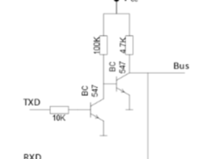
There are two ways to implement 1-Wire communication using the Raspberry Pi Pico:
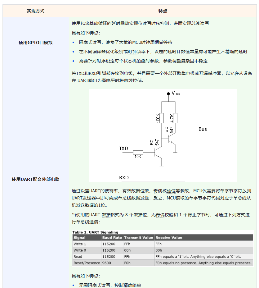

Here, we use GPIO software emulation of the 1-Wire communication protocol so that everyone can better understand the overall flow of 1-Wire communication.
2. Software Control Method
Here, we use the GPIO software emulation method to implement 1-Wire communication, referring to the following code for implementation:
First, we define the 1-Wire communication class. Its main functions are as follows:
Initialize 1-Wire communication: includes configuring the pin as open-drain with pull-up, and defining methods to disable and enable interrupts.
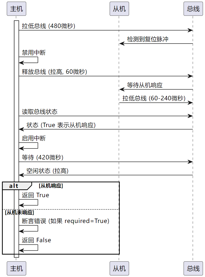
Implement the 1-Wire reset operation: includes the master sending a reset pulse and determining whether a slave responds.
Implement single-bit and single-byte read/write operations: satisfy the timing requirements by controlling the bus state and delays.
Implement multi-byte read/write operations: implemented by calling the single-byte read/write methods in a loop.
Implement the function of selecting a device with a specified ROM ID: used to select a specific slave device.
Implement a CRC8 check algorithm based on a lookup table: used to verify whether the data read from the slave device is complete and correct.
Implement the scan function: scan all devices on the bus and return all matching ROM IDs.
First, we define several commonly used command code constants for 1-Wire communication, such as the search command and the read ROM ID command:
# Define the 1-Wire communication class
class OneWire:
"""
OneWire class, used to communicate through the OneWire protocol, supporting interaction with OneWire devices (such as DS18B20 temperature sensors).
This class encapsulates the basic operations of OneWire communication, such as resetting the bus and sending/receiving data, and provides a device search function.
Attributes:
pin (Pin): the GPIO pin instance used for OneWire communication.
crctab1 (bytes): the first byte table required by the CRC lookup table method.
crctab2 (bytes): the second byte table required by the CRC lookup table method.
disable_irq (function): the function to disable interrupts.
enable_irq (function): the function to enable interrupts.
Methods:
reset(required: bool = False) -> bool: reset the 1-Wire bus.
readbit() -> int: read one data bit from the 1-Wire bus.
readbyte() -> int: read one byte from the 1-Wire bus.
readbytes(count: int) -> bytearray: read multiple bytes from the 1-Wire bus.
readinto(buf: bytearray) -> None: read multiple bytes from the 1-Wire bus into a buf array.
writebit(value: int, powerpin: machine.Pin = None) -> None: write one data bit to the 1-Wire bus.
writebyte(value: int, powerpin: machine.Pin = None) -> None: write one byte to the 1-Wire bus.
write(buf: bytearray) -> None: write the data in the buf array to the 1-Wire bus.
select_rom(rom: bytearray) -> None: send the Match ROM command.
crc8(data: bytearray) -> int: CRC check, implemented with the lookup table method.
scan() -> list[bytearray]: scan all devices on the 1-Wire bus and return all matching ROM IDs.
_search_rom(l_rom: bytearray, diff: int) -> tuple[bytearray, int]: search for the device with the corresponding ROM ID on the 1-Wire bus.
"""
# ROM commands for 1-Wire communication
CMD_SEARCHROM = const(0xf0) # Search command
CMD_READROM = const(0x33) # Read ROM ID command
CMD_MATCHROM = const(0x55) # Match ROM ID command
CMD_SKIPROM = const(0xcc) # Address all devices command
# High level value
PULLUP_ON = 1In the initialization method, we define the configuration of the pin as open-drain with pull-up, the methods to disable and enable interrupts, and the two bytes tables used for CRC checking:
def __init__(self, pin: machine.Pin) -> None:
"""
Initialize the OneWire class, passing in the data pin object to use.
Args:
pin (machine.Pin): the data pin object.
Returns:
None
"""
self.pin = pin
# Initialize the pin as pull-up, open-drain mode
self.pin.init(pin.OPEN_DRAIN, pin.PULL_UP)
# Define the methods to disable and enable interrupts
self.disable_irq = machine.disable_irq
self.enable_irq = machine.enable_irq
# Two bytes tables required by the CRC lookup table method
self.crctab1 = (b"\x00\x5E\xBC\xE2\x61\x3F\xDD\x83"
b"\xC2\x9C\x7E\x20\xA3\xFD\x1F\x41")
self.crctab2 = (b"\x00\x9D\x23\xBE\x46\xDB\x65\xF8"
b"\x8C\x11\xAF\x32\xCA\x57\xE9\x74")Then, we define the method to reset the bus, mainly implemented by controlling the high/low level of the bus and delays. For details, you can refer to the 1-Wire communication protocol layer content we discussed above:
def reset(self, required: bool = False) -> bool:
"""
Reset the 1-Wire bus.
Args:
required (bool): whether an assertion needs to be manually triggered, defaults to False.
Returns:
bool: returns True if the device sent a presence pulse; otherwise returns False, indicating failure.
Raises:
AssertionError: if required is True and the device did not respond to the reset pulse.
"""
sleep_us = time.sleep_us
pin = self.pin
# The master sends a reset pulse by pulling the bus low for 480us
pin(0)
sleep_us(480)
# Disable interrupts to prevent interrupt service routines from interrupting communication
i = self.disable_irq()
# Pull the bus high for 60us
pin(1)
sleep_us(60)
# Wait for the slave to send a presence pulse; the presence pulse pulls the bus low for 60~240us
# Read the bus state
status = not pin()
self.enable_irq(i)
# In the idle state, the pull-up resistor pulls the bus high; the master receives the presence pulse for at least 480us
# 480us - 60us = 420us
sleep_us(420)
# If status on the bus is True, it means a device responded to the reset pulse
# The program continues executing only when the assert condition is met
assert status is True or required is False, "Onewire device response"
return statusIts timing diagram is shown below:
Then we define the methods used by the master to read a single data bit, read a single byte, and read multiple bytes:
def readbit(self) -> int:
"""
Read one data bit from the 1-Wire bus.
Args:
None
Returns:
int: the read data bit (0 or 1).
"""
sleep_us = time.sleep_us
pin = self.pin
# For some devices, the bus needs to be pulled high before reading data to match CRC checking
pin(1)
# Disable interrupts
i = self.disable_irq()
# Pull the 1-Wire bus low to start reading a data bit
# The master read signal is generated by pulling the bus low for at least 1us and then releasing it
pin(0)
# Skip sleep_us(1), for compatibility with some devices that do not require strict timing
pin(1)
# The master only needs to complete sampling within 15us
sleep_us(5)
value = pin()
# Enable interrupts
self.enable_irq(i)
# The master pulls the bus high for 40us, indicating that the data bit read is complete
sleep_us(40)
return value
def readbyte(self) -> int:
"""
Read one byte from the 1-Wire bus, implemented by calling readbit 8 times.
Args:
None
Returns:
int: the read byte (0~255).
"""
value = 0
for i in range(8):
# Shift the return value of self.readbit() left by i bits and OR it with value
# to obtain a byte composed of 8 data bits
value |= self.readbit() << i
return value
def readbytes(self, count: int) -> bytearray:
"""
Read multiple bytes from the 1-Wire bus, implemented by calling readbyte multiple times.
Args:
count (int): the number of bytes to read.
Returns:
bytearray: the read binary byte array.
"""
buf = bytearray(count)
for i in range(count):
buf[i] = self.readbyte()
return buf
def readinto(self, buf: bytearray) -> None:
"""
Read multiple bytes from the 1-Wire bus into a buf array.
Args:
buf (bytearray): the binary array to place the data to read.
Returns:
None
"""
for i in range(len(buf)):
buf[i] = self.readbyte()You can see that the readinto() method, readbytes() method, and readbyte() method are all implemented by calling the readbit() method:
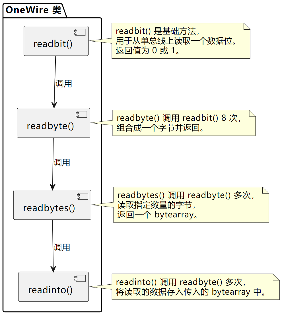
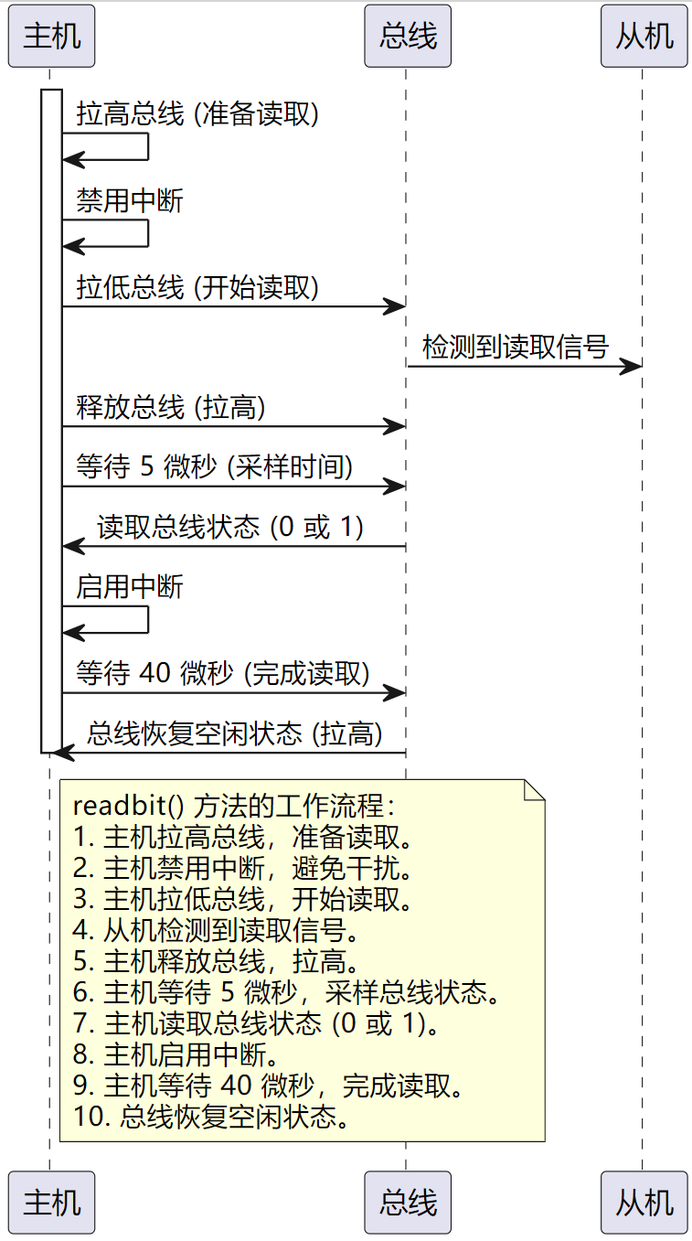
The internal working timing of the readbit() method is shown below:
Similarly, we define the methods for the master to write data to the sensor:
def writebit(self, value: int, powerpin: machine.Pin = None) -> None:
"""
Write one data bit to the 1-Wire bus.
Args:
value (int): the data bit to write, 0 or 1.
powerpin (machine.Pin): the power supply pin; pass this object when using parasitic power supply.
The default is independent power supply, so this pin is not needed.
Returns:
None
"""
sleep_us = time.sleep_us
pin = self.pin
# Disable interrupts
i = self.disable_irq()
# First pull the bus low for at least 1us (at most 15us); this is omitted here because MicroPython executes slowly
# In fact, there is already a 1us delay between the pin(0) and pin(value) statements
pin(0)
# If the data bit to send is 0, pull the bus low
# If the data bit to send is 1, pull the bus high
pin(value)
# The write signal lasts at least 60us; the slave starts sampling 15us after the master pulls the bus low
sleep_us(60)
# If parasitic power supply is used and a power pin is defined
if powerpin:
# The 1-Wire bus can intermittently provide high level to charge the slave
pin(1)
powerpin(self.PULLUP_ON)
else:
pin(1)
# Enable interrupts
self.enable_irq(i)
def writebyte(self, value: int, powerpin: machine.Pin = None) -> None:
"""
Write one byte to the 1-Wire bus, implemented by calling writebit 8 times in succession.
Args:
value (int): the value to write, 0~255.
powerpin (machine.Pin): the power supply pin; pass this object when using parasitic power supply.
Returns:
None
"""
for i in range(7):
self.writebit(value & 1)
value >>= 1
self.writebit(value & 1, powerpin)
def write(self, buf: bytearray) -> None:
"""
Write the data in the buf array to the 1-Wire bus, implemented by calling writebyte multiple times.
Args:
buf (bytearray): the binary array containing the data to send.
Returns:
None
"""
for b in buf:
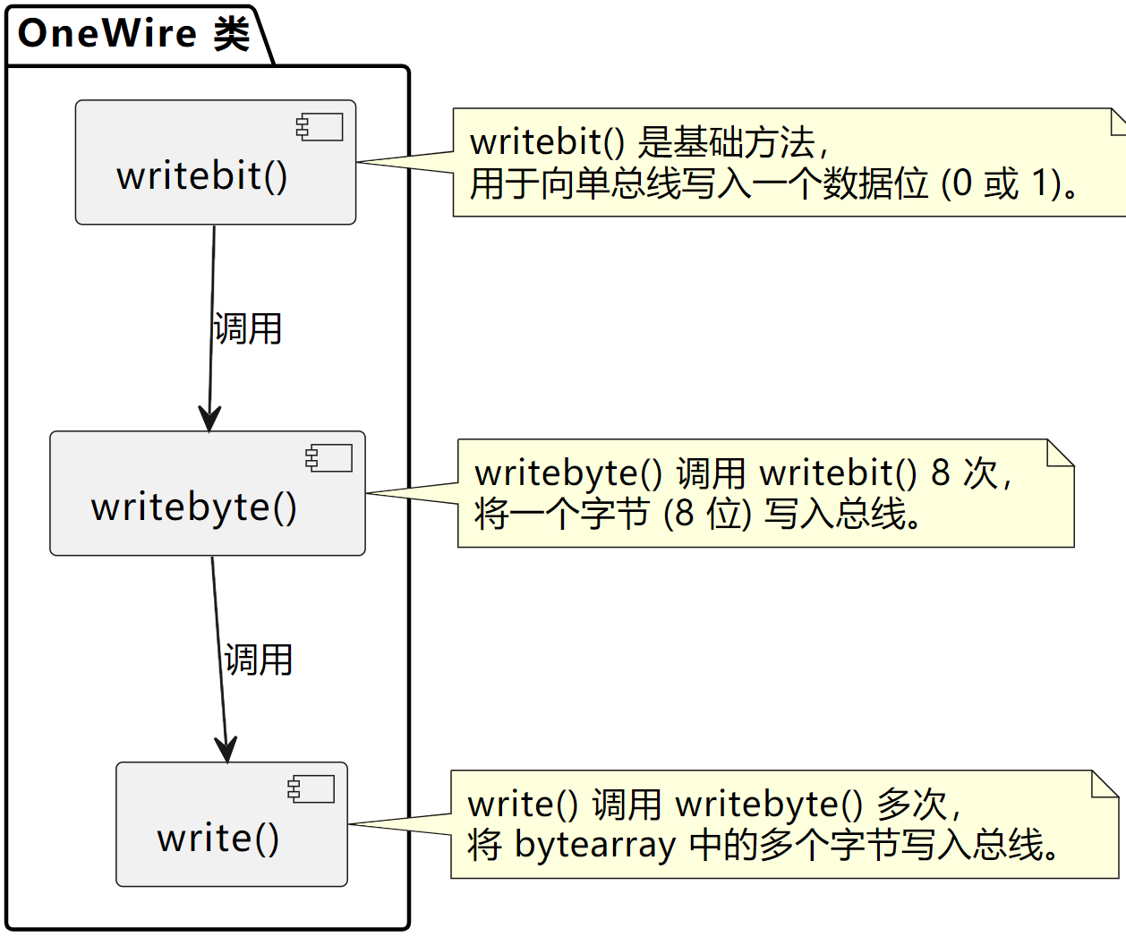
self.writebyte(b)Similarly, the writebyte() method and write() method are also implemented by calling the writebit() method:
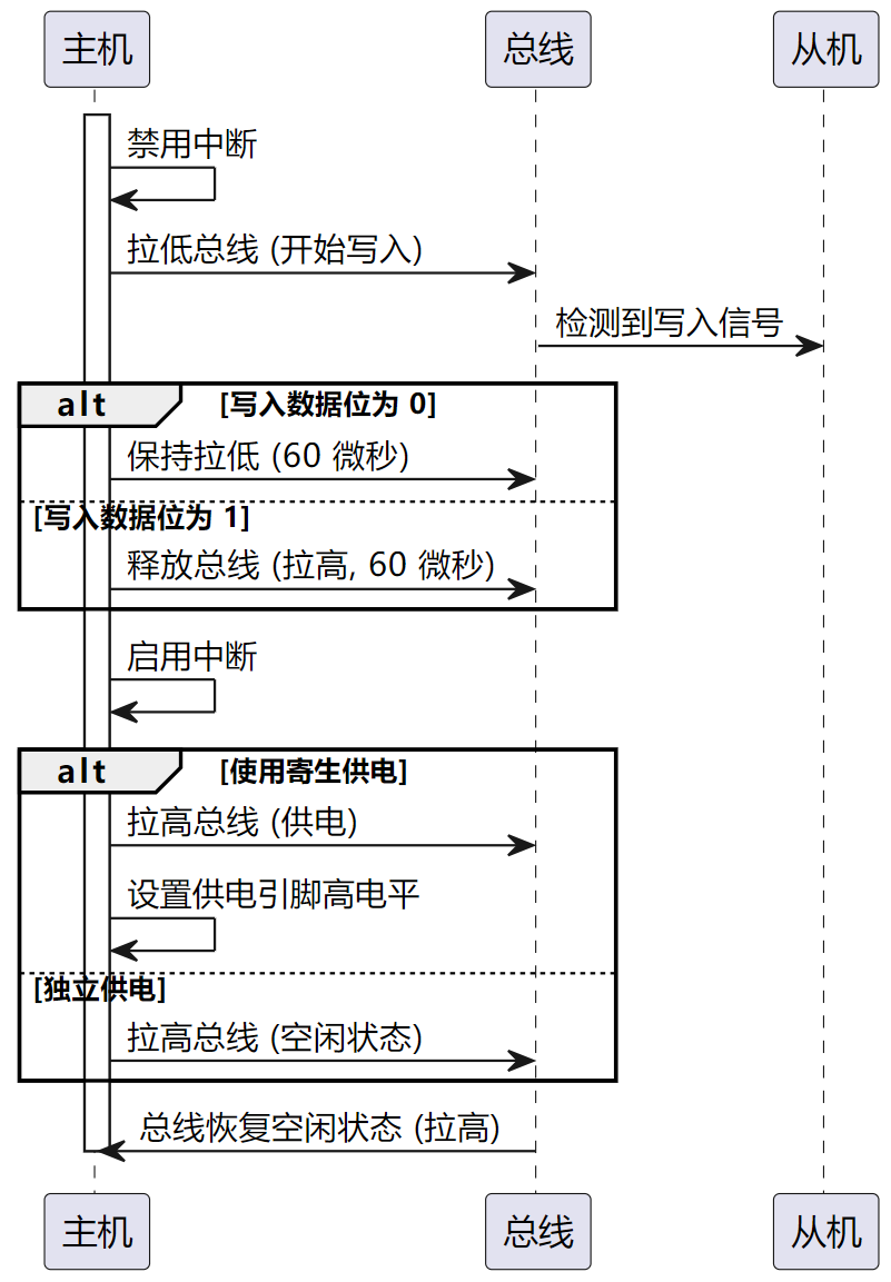
The specific working process of the writebit() method is shown below:
Then we define the method used to select the slave device with the specified ROM ID on the 1-Wire bus, mainly implemented by sending the Match ROM ID command:
def select_rom(self, rom: bytearray) -> None:
"""
Send the Match ROM ID command.
Args:
rom (bytearray): ROM ID, a bytearray of 8 bytes, 8 bytes x 8 bits = 64 bits.
Returns:
None
"""
# Initialize the bus
self.reset()
# Send the Match ROM ID command
self.writebyte(OneWire.CMD_MATCHROM)
# The master sends the ROM ID of the device to match
self.write(rom)We define the scan method used to find all connected devices on the 1-Wire bus, mainly implemented by calling the _search_rom method:
def scan(self) -> list[bytearray]:
"""
Scan all devices on the 1-Wire bus and return all matching ROM IDs.
Args:
None
Returns:
list[bytearray]: returns the ROM list of all connected devices.
Each ROM is returned as an 8-byte byte object.
"""
# List to store device ROM IDs
devices = []
diff = 65
rom = False
# Search all ROM IDs from 0 to 255
for i in range(0xff):
rom, diff = self._search_rom(rom, diff)
# If the search is successful, add the ROM ID to the list
if rom:
devices += [rom]
# If diff is 0, all devices have been searched; exit the loop
if diff == 0:
break
return devices
def _search_rom(self, l_rom: bytearray, diff: int) -> tuple[bytearray, int]:
"""
Search for the device with the corresponding ROM ID on the 1-Wire bus.
Args:
l_rom (bytearray): the ROM ID found in the last search.
diff (int): the difference position of the last search.
Returns:
tuple[bytearray, int]: if the search is successful, returns the ROM ID and the updated diff value.
"""
# Reset the bus and check whether a slave responds
if not self.reset():
return None, 0
# Send the OneWire.CMD_SEARCHROM command
self.writebyte(OneWire.CMD_SEARCHROM)
# If no ROM ID is passed in, initialize an empty ROM ID
if not l_rom:
l_rom = bytearray(8)
# Initialize the rom variable to store the finally searched ROM address
rom = bytearray(8)
# Initialize the next_diff variable to record the next difference position
next_diff = 0
i = 64
# Traverse the ROM ID from low to high, 8 bytes
for byte in range(8):
r_b = 0
# Read the 8 data bits of each byte of the ROM ID sent by the slave
for bit in range(8):
b = self.readbit()
# Read the data bit again
if self.readbit():
# If both reads are 1, i.e., both are high, the read was not successful
if b:
return None, 0
# If the two read results are different, the read was successful
# The slave sends the original code and complement of each bit
else:
if not b:
# If there is a conflict and the current position is less than the last difference position, or the current position differs from the last difference position
if diff > i or ((l_rom[byte] & (1 << bit)) and diff != i):
b = 1
# Determine the next search direction by comparing the current search position with the last search position
next_diff = i
# Write the b value back to the bus; the master needs to send each bit of the ID read
# The slave compares the data bit read by the master with the data bit sent by the slave to determine whether they match
# Then decides whether to send the next data bit
self.writebit(b)
if b:
r_b |= 1 << bit
i -= 1
rom[byte] = r_b
# Return the searched rom value and the next difference position next_diff
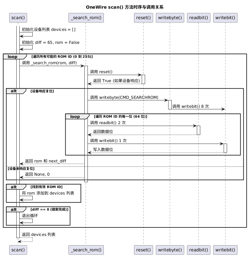
return rom, next_diffThe following figure shows the specific flow and calling relationship:
Here, we also define the commonly used CRC-8 check method, mainly using XOR operations and a lookup table to quickly check the CRC value:
def crc8(self, data: bytearray) -> int:
"""
CRC check, implemented with the lookup table method.
Args:
data (bytearray): the data to check.
Returns:
int: the CRC check value; 0 means the check passed.
"""
# Initialize the crc variable to 0
crc = 0
# Use a for loop to iterate over each byte of the input data
for i in range(len(data)):
# XOR the current crc value with the current byte value and assign the result back to crc
crc ^= data[i]
# Use the low 4 bits of the crc value as the index to look up the corresponding value in self.crctab1
# Use the high 4 bits of the crc value as the index to look up the corresponding value in self.crctab2
# XOR the two lookup results to get the new crc value
crc = (self.crctab1[crc & 0x0f] ^
self.crctab2[(crc >> 4) & 0x0f])
return crc