
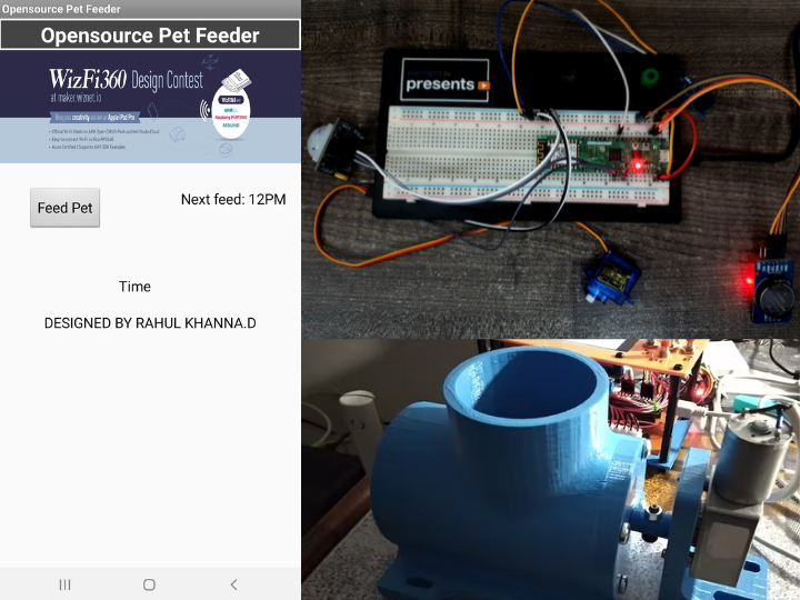
Opensource Pet Feeder using WizFi360-EVB-Pico
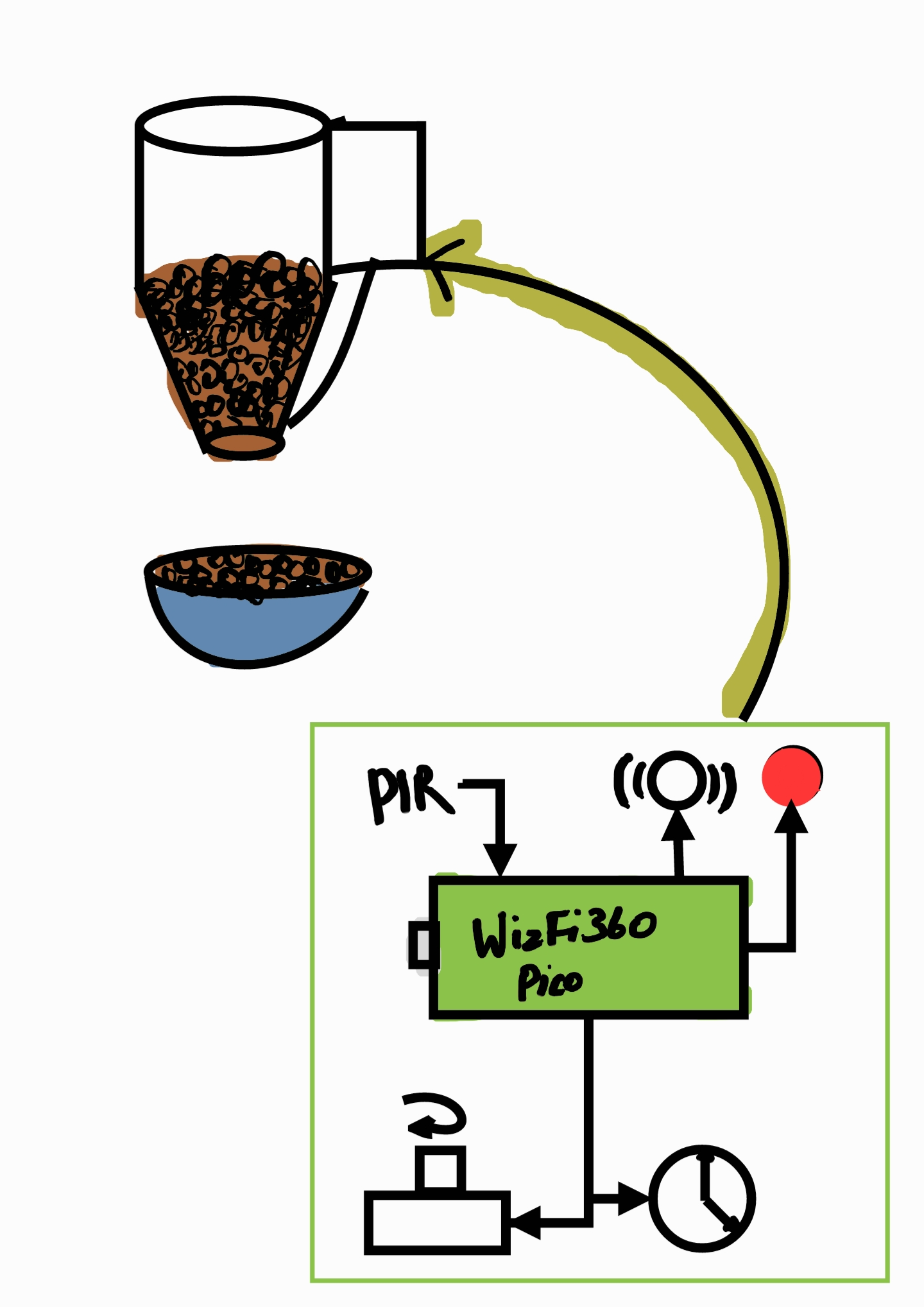
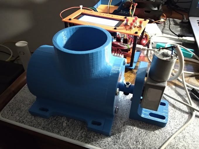
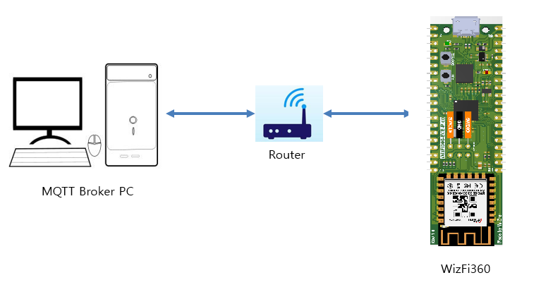
An automatic pet feeder using WizFi360-EVB-Pico controlled via WiFi. We can wirelessly control the pet feeder with an app.
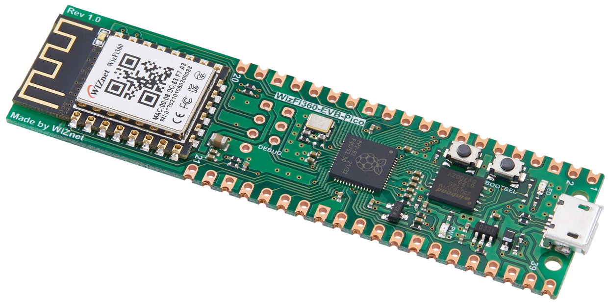
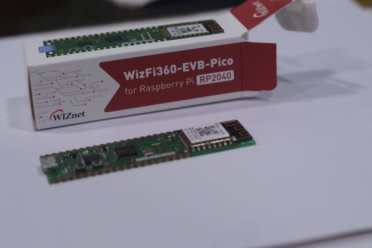
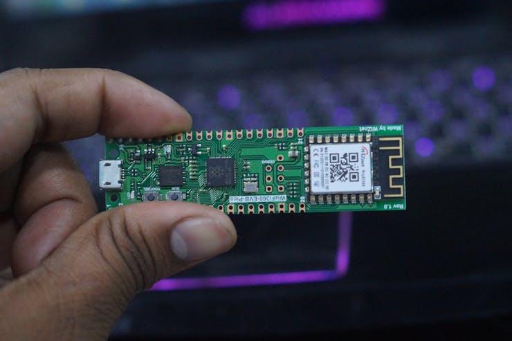
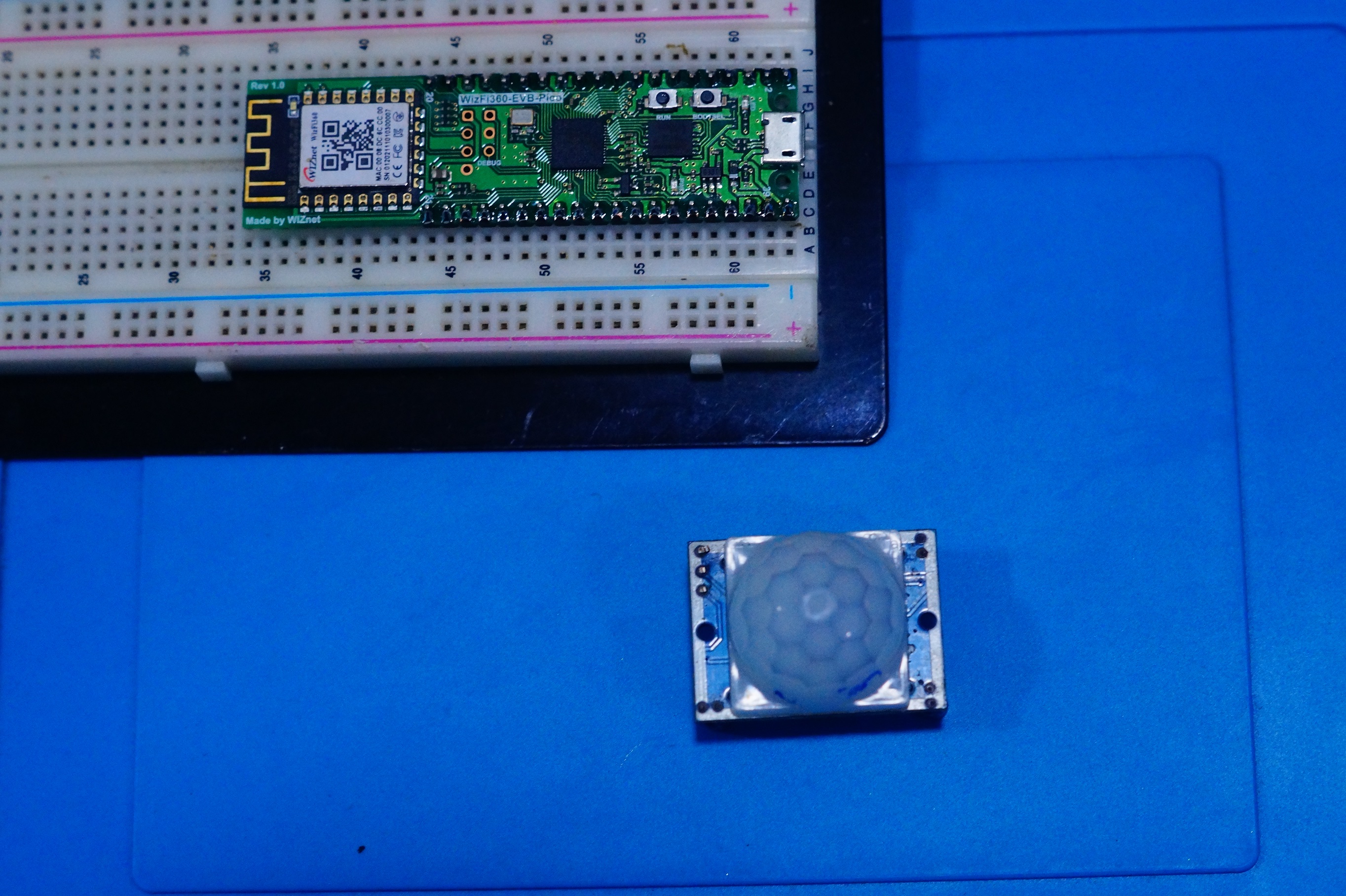
WIZnet - WizFi360-EVB-Pico
x 1
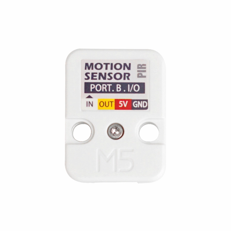
M5Stack - PIR Sensor Human Body Infrared PIR Motion Sensor (AS312)
x 1
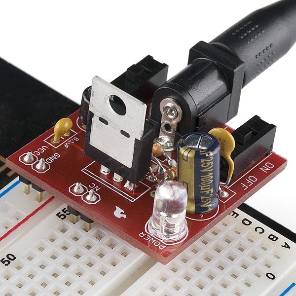
sparkfun - SparkFun Breadboard Power Supply 5V/3.3V
x 1

sparkfun - LilyPad Buzzer
x 1
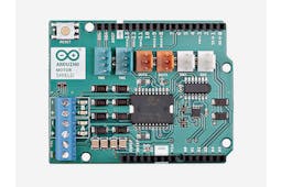
Arduino - Arduino MotorShield Rev3
x 1

seeed - Gear Stepper Motor Driver Pack
x 1

Arduino - Arduino IDE
x 1
WIZnet - WIZnet WizFi Library
x 1
WIZnet - WIZnet WizFi360-EVB-Pico-C
x 1


_AmJeP1MFNz.png?auto=compress%2Cformat&w=740&h=555&fit=max)
https://github.com/earlephilhower/arduino-pico/releases/download/global/package_rp2040_index.json_c3HfVQse4h.png?auto=compress%2Cformat&w=740&h=555&fit=max)
void setup() {
  // initialize digital pin LED_BUILTIN as an output.
  pinMode(LED_BUILTIN, OUTPUT);
}

// the loop function runs over and over again forever
void loop() {
  digitalWrite(LED_BUILTIN, HIGH);   // turn the LED on (HIGH is the voltage level)
  delay(1000);                       // wait for a second
  digitalWrite(LED_BUILTIN, LOW);    // turn the LED off by making the voltage LOW
  delay(1000);                       // wait for a second
}
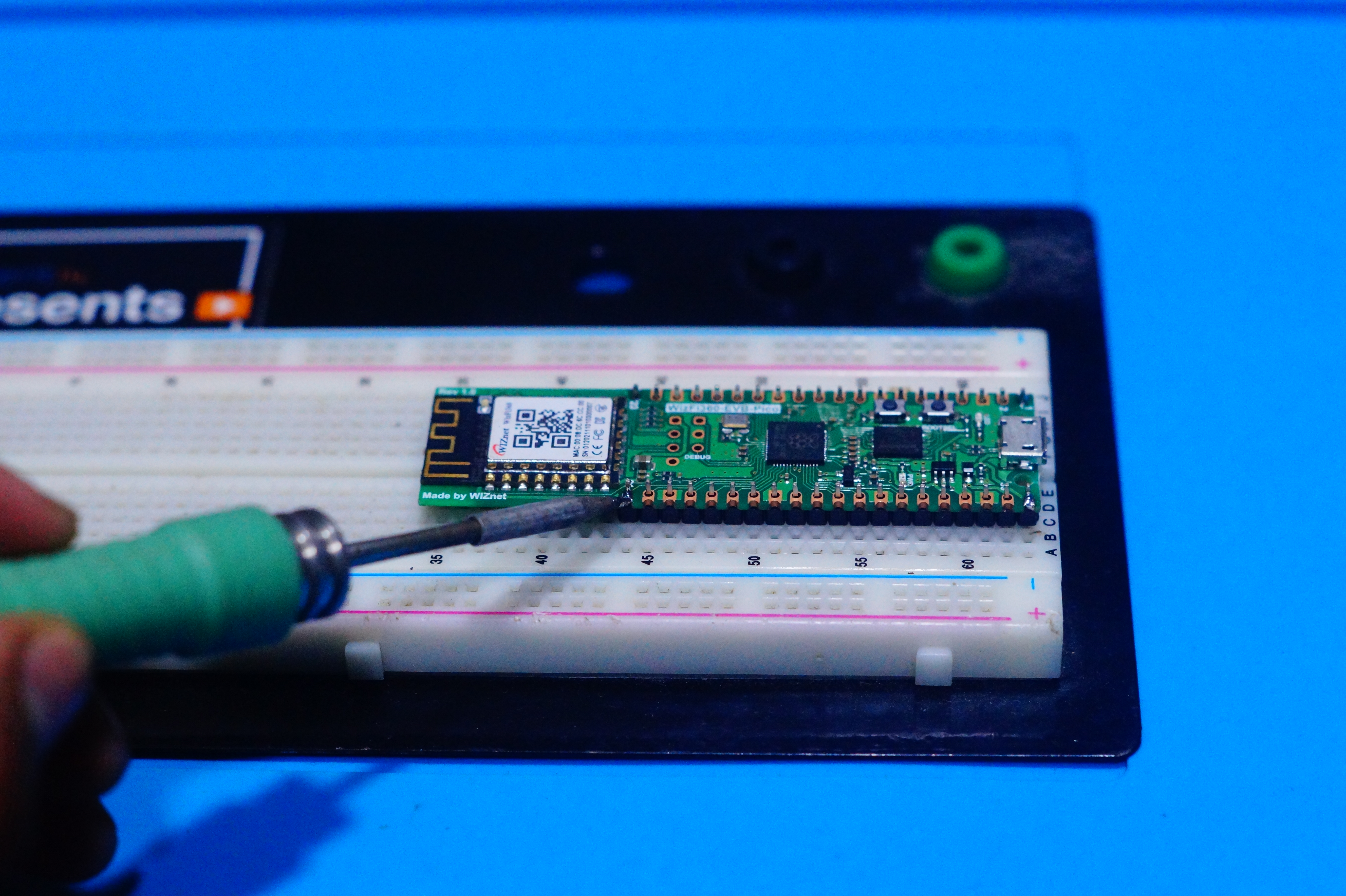
Now we have uploaded the code and the board is ready for this project.
- Download & install the following libraries.
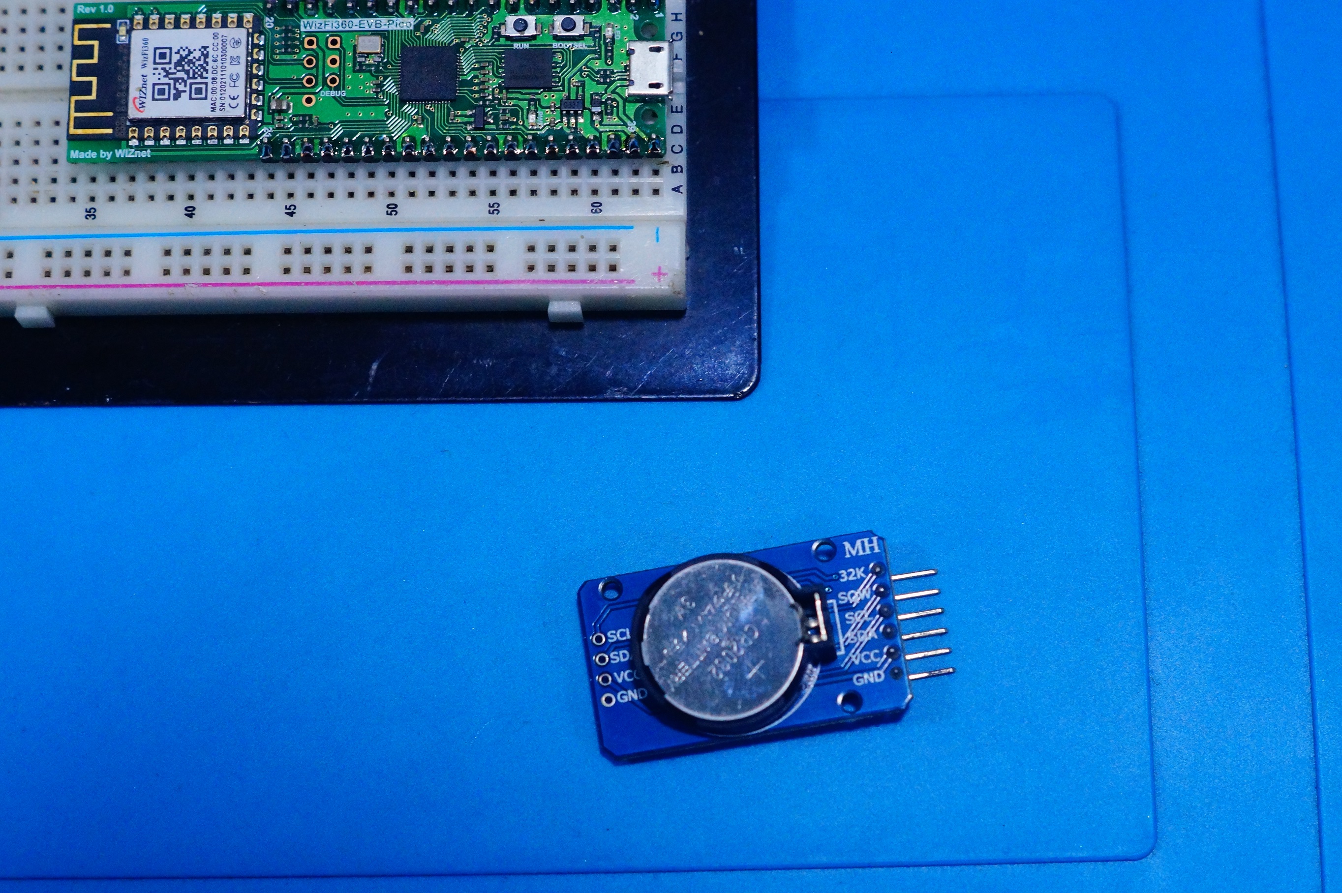
- DS3231 library
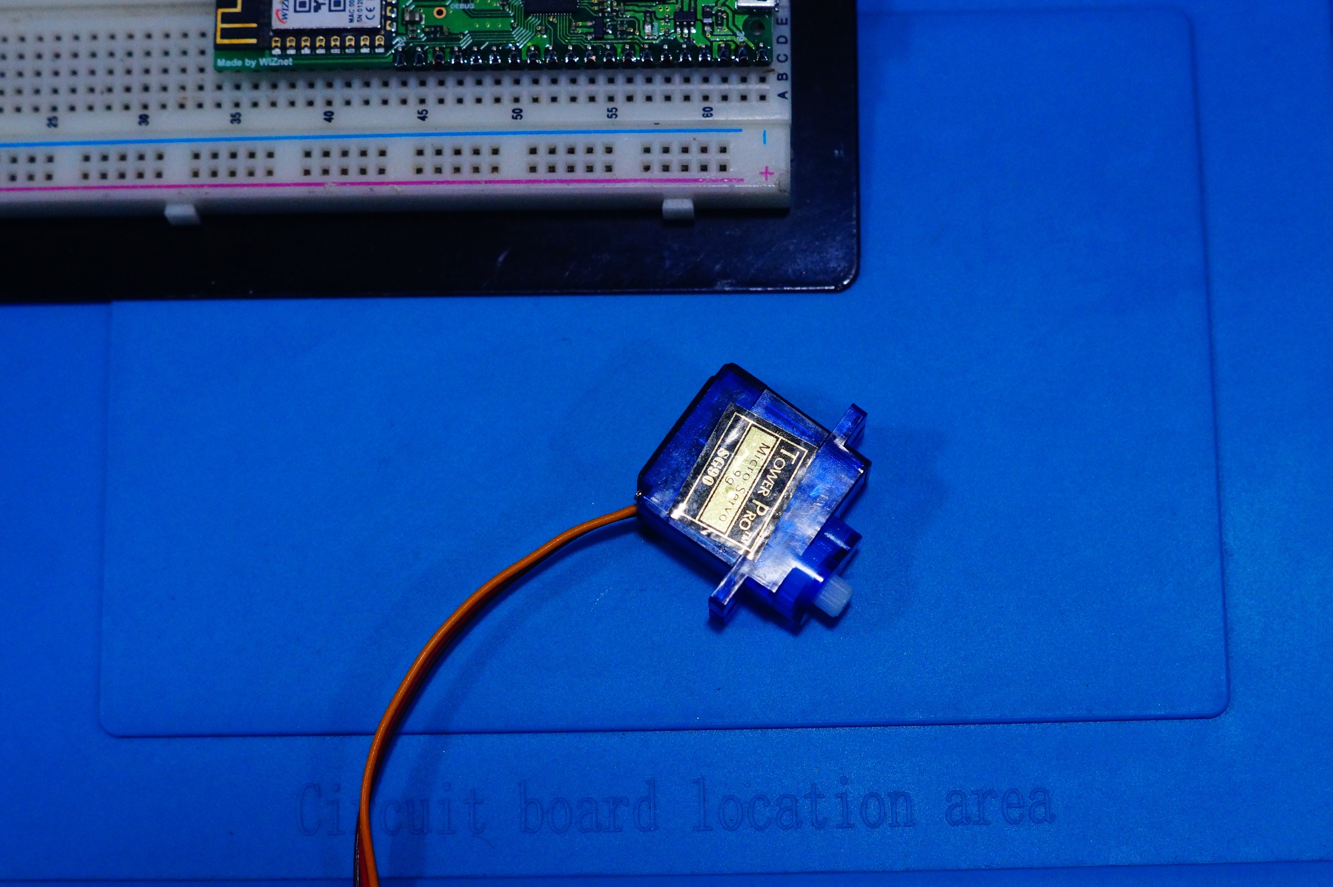
- Servo library from Arduino
- WizFi360 library - Installed in the previous steps
- MQTT client
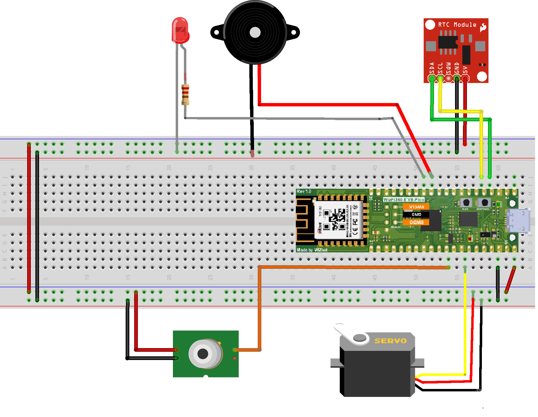
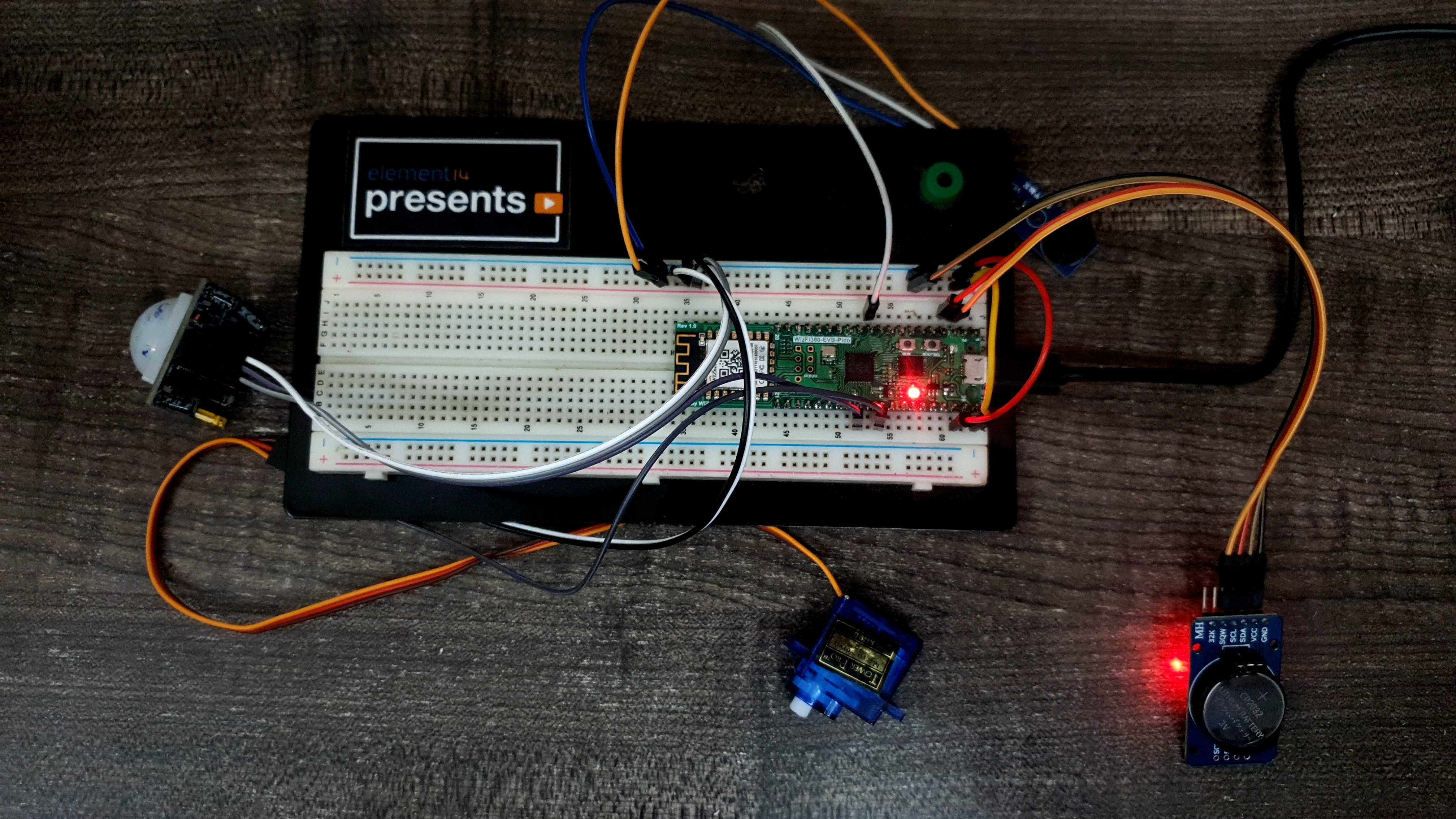
We can test the connections using the basic_peripheral.ino code.
#include <Wire.h>
#include <DS3231.h>
#include <Servo.h>

#define SENSOR_PIN 27
#define BUZZER 8

RTClib myRTC;
Servo myservo;  // create servo object to control a servo

void setup () {
  Serial.begin(115200);
  myservo.attach(28);
  Wire.begin();
  pinMode(SENSOR_PIN, INPUT);
  pinMode(BUZZER, OUTPUT);
  digitalWrite(BUZZER, LOW);
  delay(500);
  Serial.println("WizFi360 Ready!");
}

void loop () {
  int pos, sensor_val = 0;

  for (pos = 0; pos <= 180; pos += 1) { // goes from 0 degrees to 180 degrees
    // in steps of 1 degree
    myservo.write(pos);              // tell servo to go to position in variable 'pos'
    delay(15);                       // waits 15ms for the servo to reach the position
  }
  for (pos = 180; pos >= 0; pos -= 1) { // goes from 180 degrees to 0 degrees
    myservo.write(pos);              // tell servo to go to position in variable 'pos'
    delay(15);                       // waits 15ms for the servo to reach the position
  }
  sensor_val = digitalRead(SENSOR_PIN);
  if (sensor_val == 1)
  {
    digitalWrite(BUZZER, HIGH);
  }
  else
  {
    digitalWrite(BUZZER, LOW);
  }
  delay(1000);

  DateTime now = myRTC.now();

  Serial.print(now.year(), DEC);
  Serial.print('/');
  Serial.print(now.month(), DEC);
  Serial.print('/');
  Serial.print(now.day(), DEC);
  Serial.print(' ');
  Serial.print(now.hour(), DEC);
  Serial.print(':');
  Serial.print(now.minute(), DEC);
  Serial.print(':');
  Serial.print(now.second(), DEC);
  Serial.println();

  Serial.print(" since midnight 1/1/1970 = ");
  Serial.print(now.unixtime());
  Serial.print("s = ");
  Serial.print(now.unixtime() / 86400L);
  Serial.println("d");
}
A detailed explanation can be found on this website. You can find the complete code on my GitHub repo.
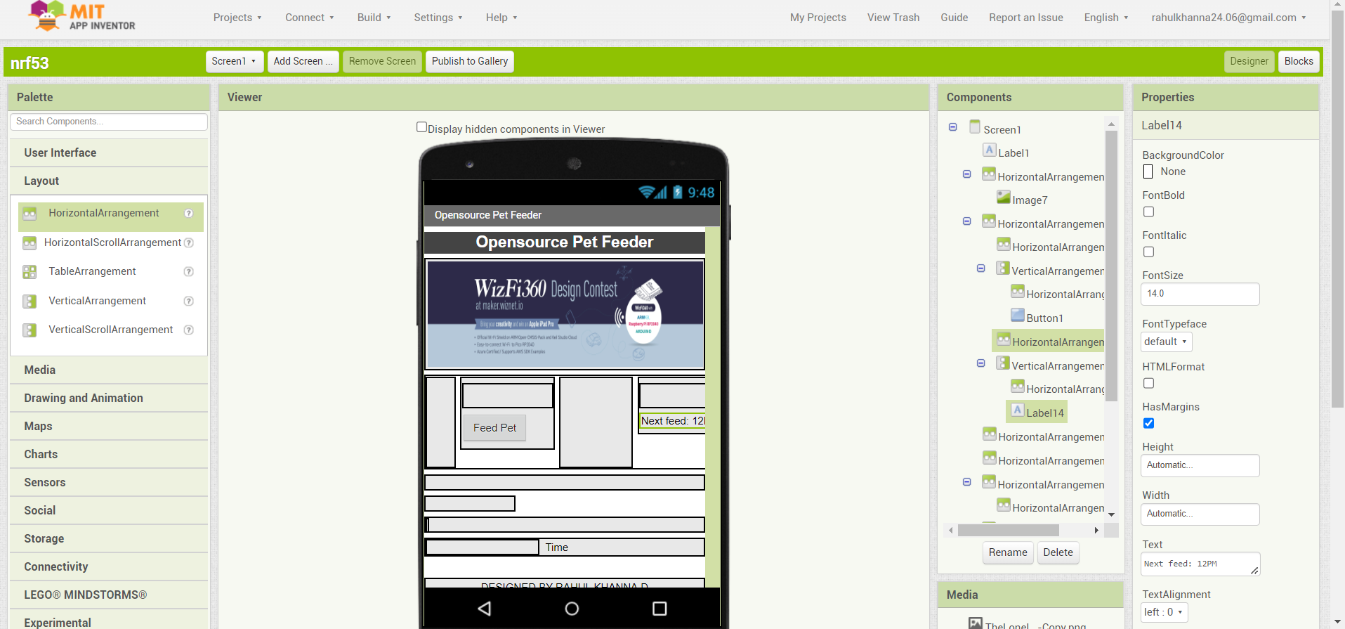
We designed the Mobile App using the MIT App inventor that is connected to the WizFi360 via MQTT. This can feed the pet from any part of the world.

Credits to Arduino, Hackster.io, Element14, App inventor & Paulo Soares
-
Project Repo


-
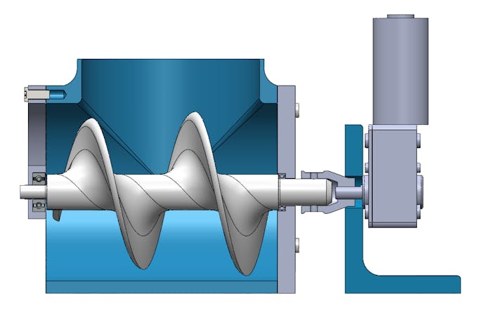
3D CAD
-
Hackster.io