
How to use PWM as W5x00 clock
Demo with W55RP20-EVB-PICO use RP2040 PWM output 25MHz as W5500 clock.
WIZnet - W55RP20-EVB-Pico
x 1
micropython - MicroPython
x 1
Story
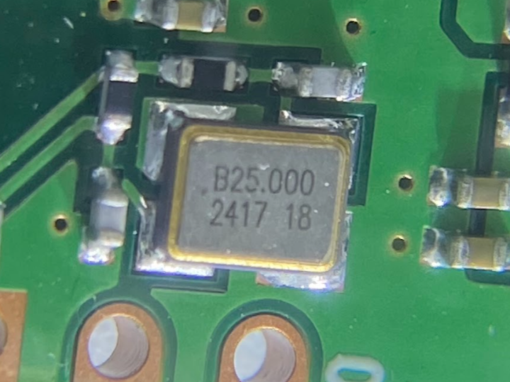
From schematic we know that W55RP20-EVB-PICO have two crystal, 12MHz for RP2040 and 25MHz for W5500 chip.
https://docs.wiznet.io/Product/ioNIC/W55RP20/w55rp20-evb-pico#schematic
This project is target to remove 25MHz and use RP2040 PWM output 25MHz as W5500 clock.
Hardware
Software
Build
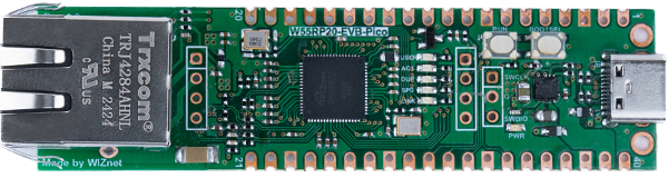
First I find out Y1 25MHz on board and with PCB file on github I identify W55-XI pin.
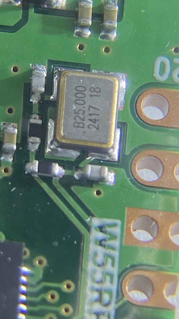
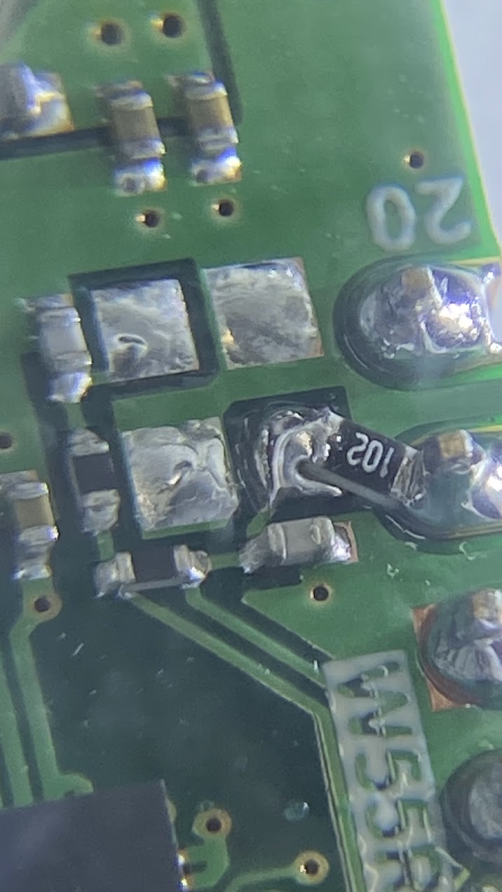
Remove Y1 and solder 1K ohm connect board pin19(GP14) and W55-XI pin.
Code
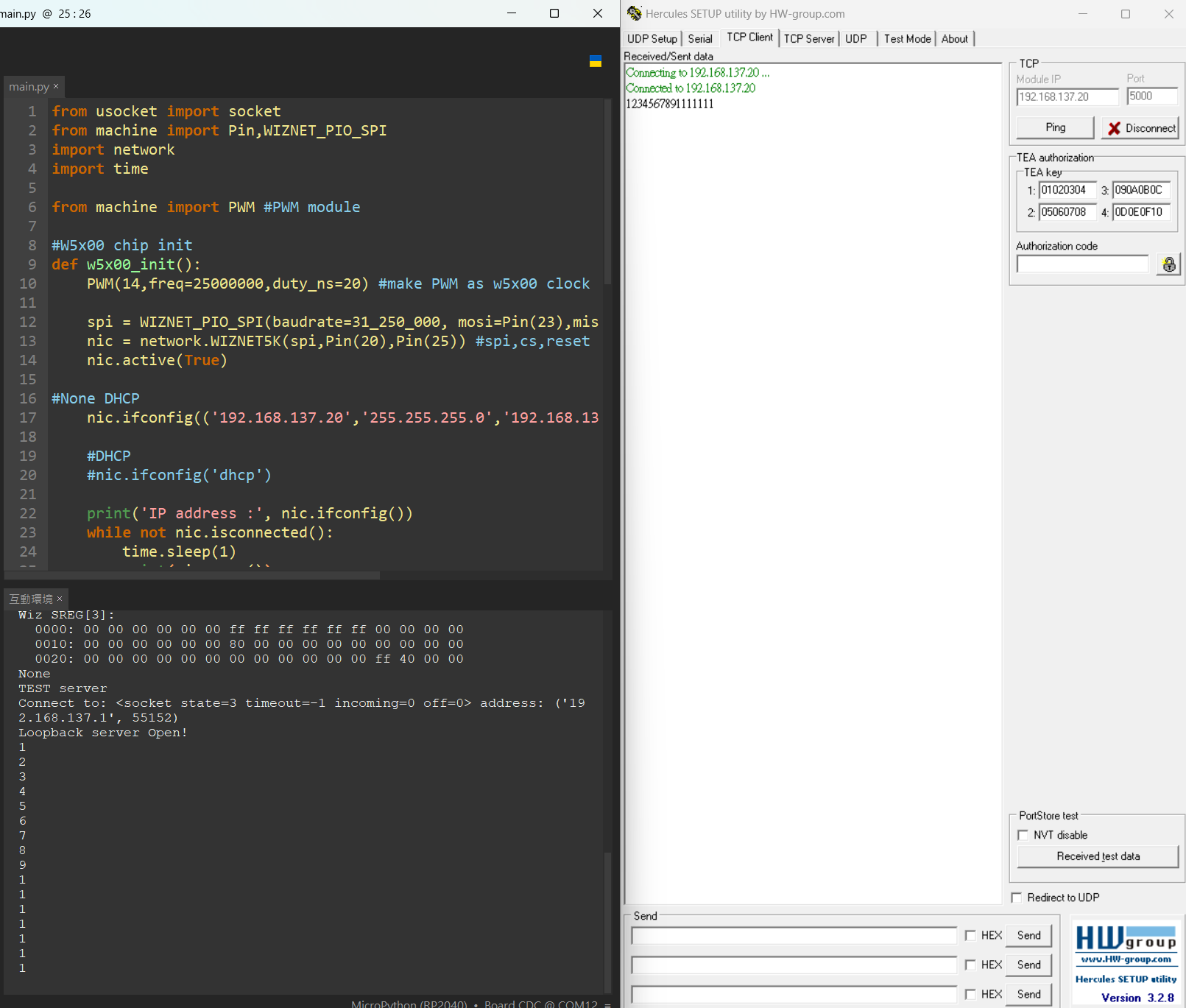
Since I remove w5500 clock, it no longer works properly. It must be given clock during initialization, use below code to output PWM.
from machine import PWM #PWM module

#W5x00 chip init
def w5x00_init():
    PWM(14,freq=25000000,duty_ns=20) #make PWM as w5x00 clock

    spi = WIZNET_PIO_SPI(baudrate=31_250_000, mosi=Pin(23),miso=Pin(22),sck=Pin(21)) #W55RP20 PIO_SPI
    nic = network.WIZNET5K(spi,Pin(20),Pin(25)) #spi,cs,reset pin
    nic.active(True)
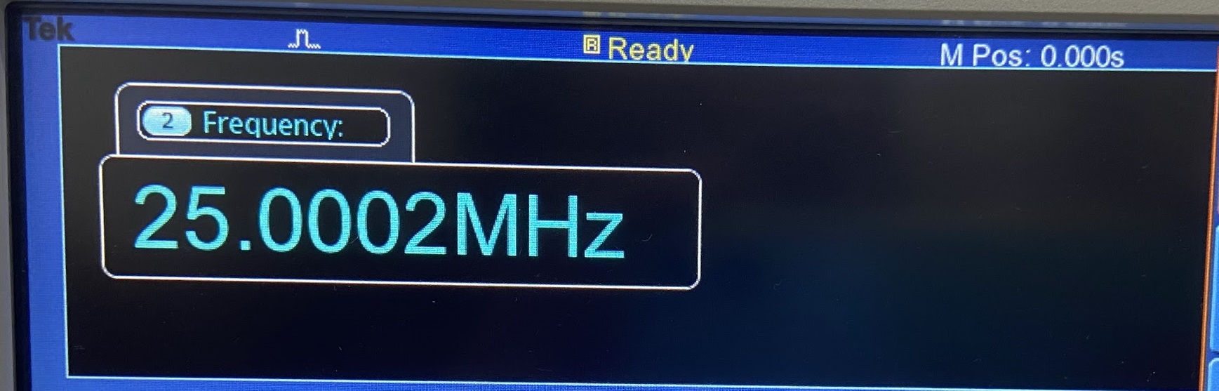
Measure PWM pin signal.
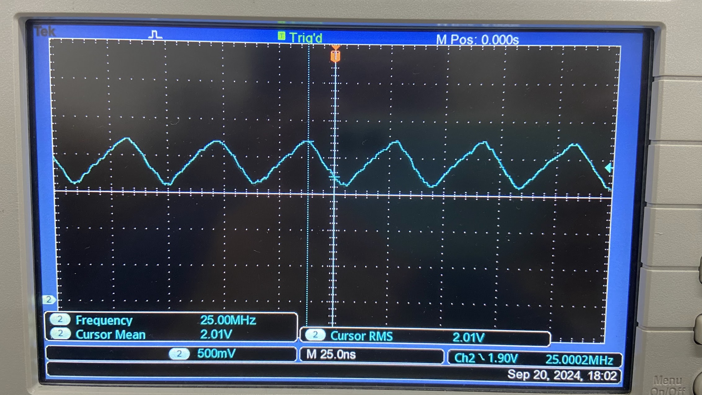
Run example Loopback, it work good as use Y1.
Conclusion
I make a simple project it can reduce the BOM cost. But the reliability requires longer testing.
-
loopback
add PWM at W5x00 chip init

-
schematics-w55rp20-evb-pico
remove Y1