Active Laser Beam Stabilization
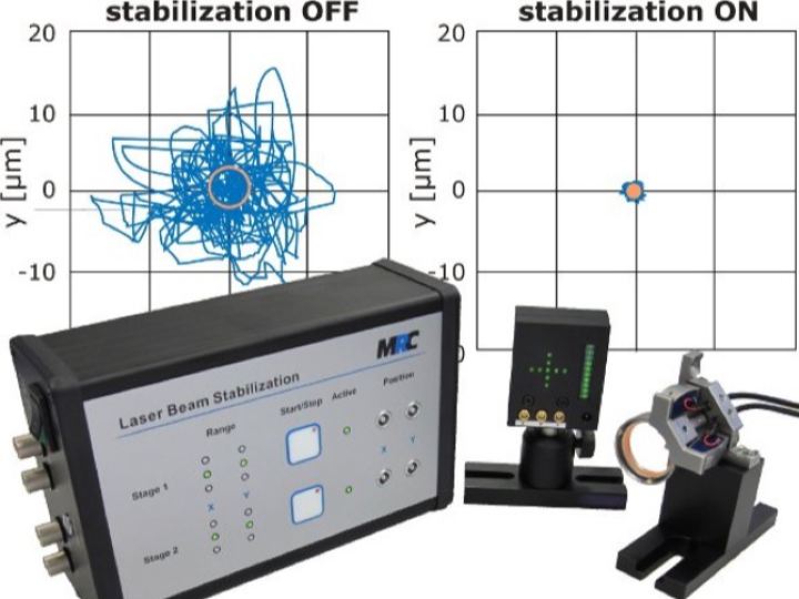
MRC Compact stabilizes laser beam position and direction, with optional WIZnet Ethernet for remote monitoring, settings, and data recording.
0
Project description
MRC Compact: Adding WIZnet Ethernet Monitoring and Configuration to Standalone Laser Beam Stabilization
source: https://www.mrc-systems.de/images/laser-strahlstabilisierung/compact.jpg
Overview
A laser being switched on does not necessarily mean its beam is reaching the correct position. Temperature changes, vibration, and moving optical components can disturb beam alignment. MRC Systems’ Compact Laser Beam Stabilization is a commercial system that uses position detectors and piezo-driven mirrors to correct these deviations. (Controller datasheet)
Applications such as coupling a laser into an optical fibre or transferring a beam between optical tables require control of both beam position and direction. Compact corrects alignment within the instrument, while an optional Ethernet interface lets users monitor its condition, record data, and change settings from a PC. (Application examples, Software datasheet)
The manufacturer’s software manual specifies WIZS2E ConfigTool for configuring the internal Ethernet module. A public reproduction of an older MRC software manual links the WIZS2E reference to W5500S2E-S1, making it a documented candidate for the Ethernet module. The installed module in an individual Compact system or current shipment has not been independently verified. (Software Manual v2.3, Historical manual reproduction)
About MRC Systems
MRC Systems GmbH is an independent company that originated from Heidelberg University and the German Cancer Research Center, DKFZ, in 1995. Based in Heidelberg, Germany, it develops and manufactures products combining optics, laser technology, electronics, software, and mechanical engineering. (About MRC Systems)
Its portfolio includes laser beam stabilization systems, MRI-compatible cameras, eye-tracking equipment, and stimulators for quantitative sensory testing. The company’s history records the launch of a new Compact system in 2010, followed by developments in detectors, mirror actuators, and software. This is the development history of the optical system, not the adoption date of a particular Ethernet module. (MRC News and company history)
What Is the Compact System?
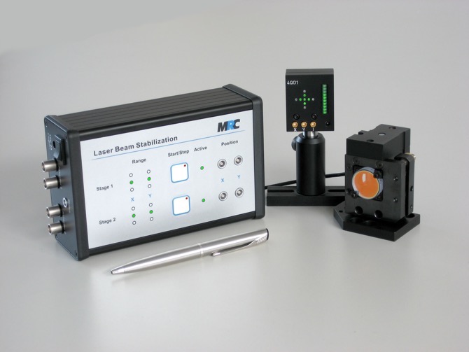
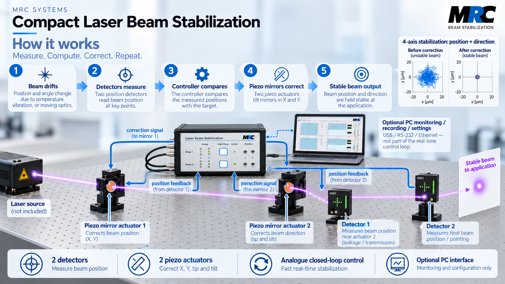
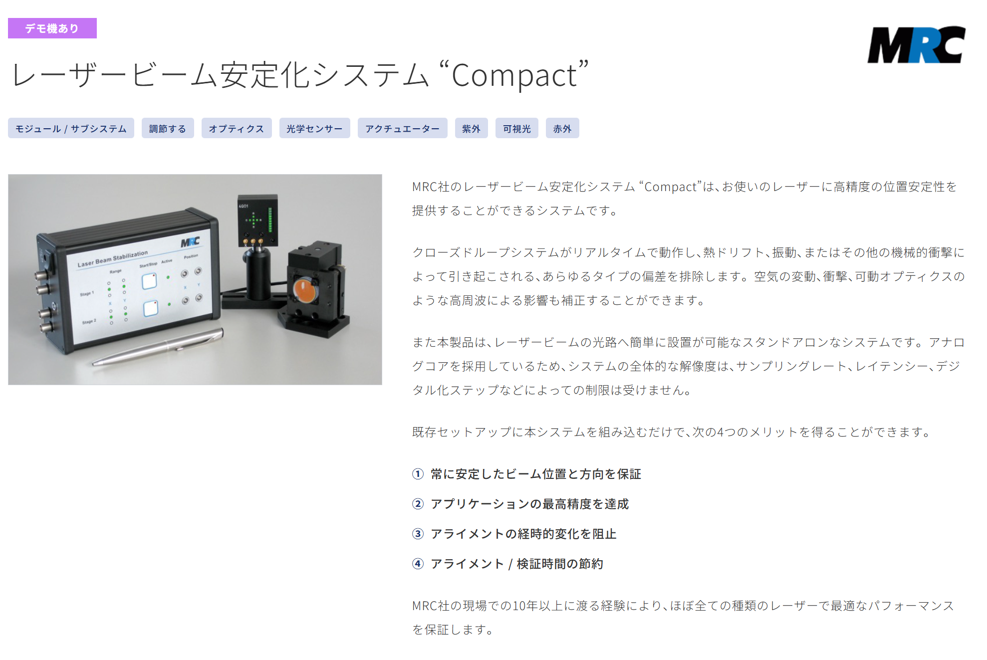
Compact is not a laser source. It is a system for correcting the position and propagation direction of an external laser beam. A typical four-axis configuration consists of one controller, two position detectors, and two two-axis piezo mirror actuators. These components are positioned along the optical path so the system can be integrated into existing equipment. (Setup configurations)
The detectors measure where the beam arrives, while the piezo actuators make small adjustments to mirror tilt. The control circuits, amplifiers, and power-related electronics are integrated into a single enclosure with operating controls. (Compact User Manual v15)
Main Specifications and Configuration
| Item | Manufacturer-Published Information |
|---|---|
| Controlled variables | Laser beam position and propagation direction |
| Typical configuration | Four-axis system with two position detectors and two two-axis piezo mirror actuators |
| Control method | Analogue closed-loop control; standalone operation without a PC |
| Standard visible-range detector | 320–1,100 nm; separate UV and IR detector options |
| Example mirror actuator | P2S30, with a standard one-inch mirror |
| P2S30 stabilization bandwidth | Approximately 400 Hz with a one-inch mirror |
| Communication options | USB, RS-232, or Ethernet |
| PC software | Windows 10/11 64-bit and Linux Ubuntu |
| Controller supply | 12 V DC |
| Controller dimensions | 166 × 106 × 56 mm, width × height × depth, according to User Manual v15 |
The specifications follow User Manual v15 and Software Manual v2.3. Wavelength coverage and stabilization bandwidth depend on the selected detector and mirror configuration. The approximately 400 Hz figure applies to the P2S30 with a one-inch mirror and is a manufacturer specification, not an independent test result. (User Manual v15, Software Manual v2.3)
How It Works
AI-generated image
Why Both Position and Direction Matter
Even when a beam passes through the same point, a change in its propagation angle changes where it reaches equipment farther along the optical path. Aligning the beam at one point therefore does not necessarily preserve alignment throughout the system.
Compact’s four-axis configuration uses two mirror–detector pairs to control horizontal and vertical position together with two angular degrees of freedom. Depending on the optical arrangement, the detectors can receive a small amount of light transmitted through the mirrors or a portion diverted by beam splitters. (Setup configurations)
Correcting Detected Deviations Through Mirror Movement
When a detector senses a deviation from the target position, the controller adjusts the mirror tilt through the piezo actuator. Measurement and correction repeat as a closed-loop process. Fast correction is handled by the internal analogue circuitry; the manufacturer states that the control loop remains analogue even when digital communication is added. (Controller datasheet)
In other words, the instrument stabilizes the beam, while Ethernet provides access to its status and settings from a PC. The network does not replace the real-time optical correction loop.
Role of WIZnet
An Internal Ethernet Module Documented by the Manufacturer
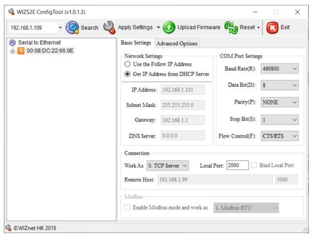
Page 7, Section 6.3, “Ethernet module,” in Software Manual v2.3 describes configuring an Ethernet-equipped system with WIZS2E ConfigTool. After the instrument is powered on, the tool displays the MAC address of the connected beam stabilization system and allows device discovery and network configuration. (Software Manual v2.3)
The same manual specifies TCP server mode, a default port of 2000, and a 460,800-baud serial connection with CTS/RTS flow control between the controller and Ethernet adapter. These are concrete operating settings connecting serial control data to Ethernet, rather than simply a statement that the product has a network connector. (Software Manual v2.3)
Official Software Manual v2.3 — Ethernet configuration, pages 7–8
Historical Documentation Points to W5500S2E-S1
Software Manual v2.1, dated January 26, 2021, also describes an internal Ethernet module and the WIZS2E configuration procedure. Copies of this manufacturer-authored PDF are available from MRC and distributor Opto Science. (MRC’s older software manual, Opto Science copy)
In a public HTML reproduction of that manual, the WIZS2E ConfigTool link points to the W5500S2E-S1 product page, and W5500S2E-S1 also appears in the references. This makes W5500S2E-S1 a documented candidate rather than a guess based solely on the tool’s name. However, the model reference was verified in the reproduction, not through a manufacturer bill of materials or a readable marking on the installed module. (Historical manual reproduction and references)
Manufacturer Software Manual v2.1 — page 12
Candidate Module Architecture and the Limits of Identification
WIZnet’s official documentation identifies W5500S2E-S1 as a Serial-to-Ethernet module combining a W5500 Ethernet chip with an STM32F103 MCU. That hardware description is confirmed for the module itself. (W5500S2E-S1 documentation)
However, WIZS2E ConfigTool supports multiple families, including W5500S2E and W7500S2E. The historical reference narrows the candidate to W5500S2E-S1, but it does not establish that every Compact system—or every currently shipped Ethernet configuration—contains that module. The candidate module’s STM32F103 should also not be confused with the main processor of the entire Compact system. (WIZS2E ConfigTool documentation)
What Does Ethernet Enable in Practice?
Connection — use an address appropriate to the installation. Ethernet-equipped systems ship in DHCP mode. Users connect through the assigned IP address; for a direct PC connection without a DHCP server, the documentation explains how to configure a fixed IP address using WIZS2E ConfigTool. (Communication protocol)
Monitoring and recording — see how the beam changes over time. MRC’s software displays detector x/y positions, light intensity, and piezo drive voltages. Time plots, beam-position statistics, and data recording provide a view of operating behaviour beyond a single instantaneous reading. (Software datasheet)
Configuration and integration — manage the instrument from an experimental setup. Supported functions include starting and stopping control loops and adjusting proportional-control parameters. Target-position adjustment requires the appropriate hardware option. Manufacturer software is supplied with interface-equipped systems, and a version for managing multiple systems is also available. (Software datasheet)
MRC publishes the communication protocol for integration with custom applications. This makes the method of communicating with the instrument publicly available; it does not mean that the complete Compact circuitry or firmware is open source. (Communication protocol)
Products and Purchasing Channels
source: https://www.optoscience.com/our-vendors/mrc-systems/laser-beam-stabilization.html
MRC supplies a beam stabilization system assembled from a controller, detectors, and piezo mirror actuators, rather than an Ethernet module alone. Components are selected for the laser wavelength, mirror size, and installation environment. Vacuum-compatible configurations and OEM versions are also offered. (Official product page)
The manufacturer’s product page directs buyers to telephone and email enquiries rather than a published price and immediate checkout. Purchasing therefore involves confirming the complete configuration, including detectors, actuators, and the required communication interface. (MRC product and quotation information)
In Japan, Opto Science maintains a dedicated Compact product page and enquiry route, with a demonstration-unit availability notice. This establishes a product demonstration and sales channel, not the inventory or sales volume of a particular Ethernet-equipped configuration. (Opto Science product page)
Application Market and Documented Use Cases
Compact serves beam alignment and stabilization in precision optical experiments and laser-processing equipment. Published application material covers fibre coupling, beam transfer between optical tables, laser micromachining with moving stages, and pump–probe experiments. Each example explains an alignment requirement and an appropriate optical arrangement. (Application examples)
There is also deployment information beyond the product catalogue. MRC’s 2020 anniversary material states that two Compact systems were installed in the CHARM—CH₄ Atmospheric Remote Monitoring—helicopter remote-sensing system. The same material describes Compact being used in laser cutting of lenses for mobile phones. (25 Years of MRC Systems)
These examples establish applications of the product family, but they do not identify whether the installations included Ethernet options or WIZnet modules. The reviewed public sources did not establish cumulative Compact sales, annual shipments, or the share sold with Ethernet. The two CHARM systems are a quantity from a specific application, not a measure of overall sales.
Product Communication Through Exhibitions, Technical Resources, and Social Media
Presenting Beam Stabilization at Specialist Exhibitions
MRC’s official News page includes announcements for LASER World of PHOTONICS 2025, Photonics West 2026, and the DPG Spring Meeting 2026. Its Photonics West communication includes product demonstrations, showing an approach directed at optics researchers and equipment developers. (MRC News)
Technical Content Supporting Selection and Integration
The official product page provides quick-start guides, detailed manuals, application configurations, and communication documentation. Opto Science connects Japanese-language product and application material with demonstration and purchasing enquiries. This content helps customers evaluate a configuration before purchase and integrate it into an optical system afterward. (MRC product resources, Opto Science applications)
MRC Systems’ LinkedIn company page provides company information and a connection to the official website. The product-specific promotional material verified for this review consists of exhibition announcements and product documentation; LinkedIn posting frequency and advertising performance were not assessed. (MRC Systems on LinkedIn)
Why This Product Matters
Compact illustrates adding network monitoring and configuration to a precision instrument that operates independently. Users can inspect operating conditions, review measurement history, and send settings without calculating beam corrections on the PC. The underlying stabilization remains an analogue control process. (Controller datasheet)
WIZnet’s relevance is not that it replaces optical control. It provides a communication interface carrying data between an established control system and a PC. The historical W5500S2E-S1 reference adds a useful identification clue, but it does not replace verification of the installed module or establish the manufacturer’s reason for selecting it. (Software Manual v2.3, Historical reference)
Current Status and Limitations
Actual stabilization performance depends on the detector, beam diameter and intensity, optical distances, and mirror actuator. Low-repetition-rate pulsed lasers or operation with periods when the laser is off may require additional functions such as Sample & Hold. (Compact User Manual v15)
The software manual’s 500 Hz upper setting for TCP/IP data acquisition concerns reading data on the PC. It is different from the approximately 400 Hz stabilization bandwidth specified for the P2S30 configuration. Actual acquisition performance also depends on the PC and network environment. (Software Manual v2.3)
Documentation versions also differ. The default serial speed for the Ethernet adapter is listed as 921,600 baud in the 2021 manual and 460,800 baud in the 2026 manual. Controller width is given as 166 mm in User Manual v15 and 184 mm in the 2021 controller datasheet. These differences alone do not establish a change of internal module; installation and configuration should follow the documentation applicable to the supplied system. (2021 software manual, 2026 software manual, User Manual v15, Controller datasheet)
Related WIZnet Maker Projects
| Related Curation | Network Role and Comparison with Compact |
|---|---|
| BR Remote MFC2 | Adds optional IP connectivity to a professional camera and remote-head controller. Its emphasis is transferring operating commands, while Compact adds monitoring and configuration to independently performed beam correction. |
| humimeter LF-TD-E | Transfers humidity and temperature measurements over Ethernet. Its primary role is measurement-data collection, whereas Compact is an active control system that uses detector feedback to move mirrors. |
The basic roles of these products are also described in their manufacturers’ product information. The comparison distinguishes what Ethernet does in each instrument; it does not imply identical internal modules, shared protocols, or interoperability. (BR Remote MFC, humimeter LF-TD-E)
Conclusion
MRC Compact is a commercial system for maintaining laser beam position and direction. Its Ethernet option connects independently performed beam stabilization with PC-based monitoring, recording, and configuration. (Software datasheet)
WIZnet involvement is documented in the manufacturer’s internal Ethernet-module setup procedure, while a historical manual reproduction identifies W5500S2E-S1 as a specific candidate. Even without a conclusive identification of the installed module, the documentation shows how control data from a precision optical instrument is made accessible over a network. (Software Manual v2.3, Historical manual reproduction)
FAQ
Q. Does Compact generate a laser beam?
A. No. It detects the position and direction of an external laser beam and corrects deviations through piezo-driven mirrors. (Setup configurations)
Q. Does stabilization require Ethernet or a PC?
A. Basic stabilization operates independently. Communication interfaces and software add monitoring, recording, and configuration functions. (Controller datasheet)
Q. Which WIZnet module appears to be involved?
A. A public reproduction of an older manual references W5500S2E-S1. That candidate module contains W5500 and STM32F103, but the installed module in an individual Compact system or current shipment requires separate confirmation. (Historical manual reproduction, W5500S2E-S1 documentation)
Q. Can it be integrated with custom experimental software?
A. MRC publishes the communication protocol for integration. Available configuration functions depend on the hardware options included in the purchased system. (Communication protocol)
Source Snapshot
Review date: September 29, 2026
Scope: The Ethernet-equipped configuration of MRC Compact Laser Beam Stabilization.
Main documents: System User Manual v15, Software Manual v2.3, and historical Software Manual v2.1.
WIZnet evidence: The manufacturer documents internal Ethernet setup with WIZS2E ConfigTool. W5500S2E-S1 is a candidate identified through a historical manual reproduction; the installed module in individual instruments and the current shipping configuration remain unconfirmed.
| Source | What It Supports | URL |
|---|---|---|
| MRC official product page | Product configuration, communication options, quotations, and downloads | Laser Beam Stabilization |
| System User Manual v15, January 2026 | Operating principles, optical and mechanical specifications, and configuration options | User Manual v15 |
| Software Manual v2.3, January 2026 | WIZS2E setup on pages 7–8, default communication settings, and data acquisition | Software Manual v2.3 |
| Software Manual v2.1, January 26, 2021 | Historical internal Ethernet-module setup and communication settings | MRC PDF · Opto Science copy |
| Public reproduction of the historical manual | W5500S2E-S1 reference in the WIZS2E link and reference list; supporting evidence, not installed-component verification | Manual reproduction and references |
| WIZnet official documentation | W5500S2E-S1’s W5500 and STM32F103 architecture, and configuration-tool support | W5500S2E-S1 · WIZS2E ConfigTool |
| Controller datasheet, November 2021 | Separation of analogue control and digital communication; historical dimensions | Controller Datasheet |
| Software and communication documentation | Supplied software, display, recording, settings, and custom-program integration | Software Datasheet · Communication Protocol |
| Optical setup guide | Detector and mirror placement; two-axis and four-axis configurations | Setup Configurations |
| MRC company history and applications | Company origins, product history, two Compact systems in CHARM, and lens-processing use | About · News · 25 Years MRC |
| Opto Science | Japanese sales and demonstration enquiries, with application-specific information | Product · Applications |
| MRC LinkedIn | Company information and link to the official website | MRC Systems GmbH |
