


STM32-网络通讯32路DIDO控制板
STM32-网络通讯32路DIDO控制板

WIZnet - W5500
x 1

프로젝트 개요
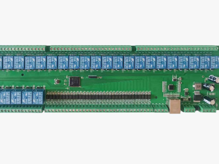
이 프로젝트는 STM32F103VCT6를 기반으로 32채널 디지털 입력(DI)을 모니터링하고 32채널 릴레이 출력(DO)을 원격 제어하는 산업용 Ethernet I/O 보드입니다. 네트워크 인터페이스에는 WIZnet W5500을 사용하며, PC, HMI, PLC와 같은 Modbus TCP 클라이언트가 Ethernet을 통해 현장 신호를 읽거나 릴레이를 제어할 수 있습니다.
전체 구조는 입력과 출력 방향으로 나누어 볼 수 있습니다.
입력
센서·스위치 → 32 DI → STM32F103VCT6 → W5500 → Ethernet → Modbus TCP Client
출력
Modbus TCP Client → Ethernet → W5500 → STM32F103VCT6 → 32 Relay DO → 현장 부하
STM32F103VCT6은 실제 디지털 입력 상태를 확인하고 릴레이 출력을 제어하며, W5500은 외부 네트워크와 연결되는 TCP/IP 통신 경로를 담당합니다.
기본 네트워크 주소는 고정 IP 192.168.0.8로 설정되어 있습니다. 보드 전원은 DC 9~36V이며, 원문 기준 릴레이 접점은 최대 220V/10A 부하를 대상으로 합니다.
이러한 구성은 여러 개의 센서와 접점 출력을 하나의 Ethernet 노드에 모아야 하는 공장자동화 환경에 적합합니다. PLC나 HMI에서 별도의 로컬 배선을 길게 구성하는 대신, 현장 가까이에 I/O 보드를 배치하고 Modbus TCP를 통해 상태 감시와 출력 제어를 수행할 수 있습니다.
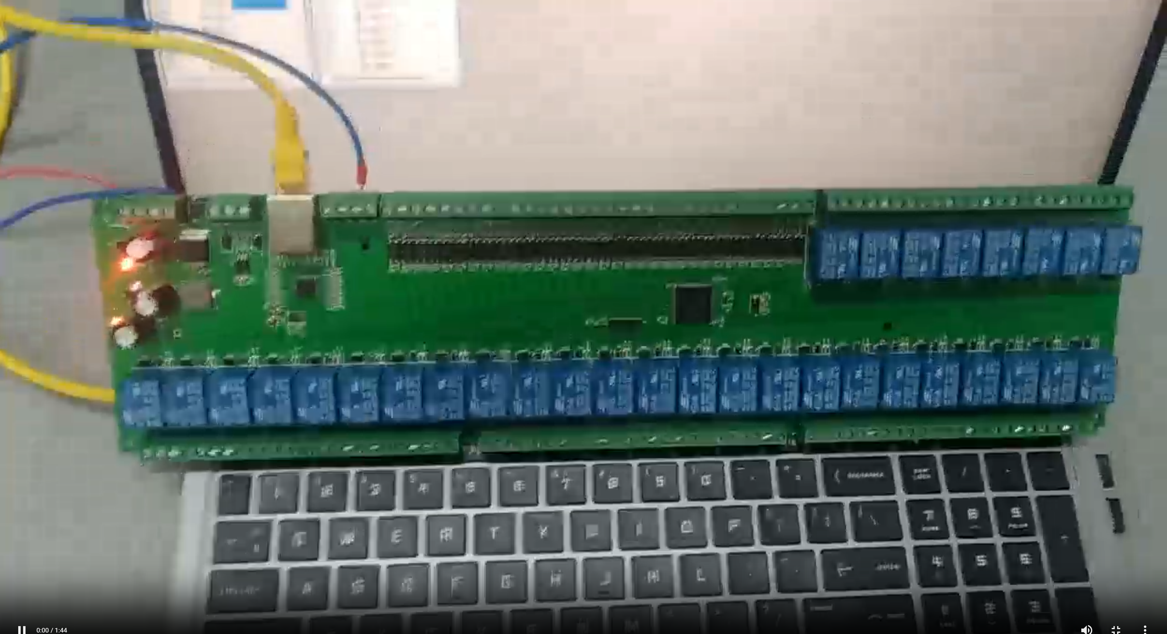
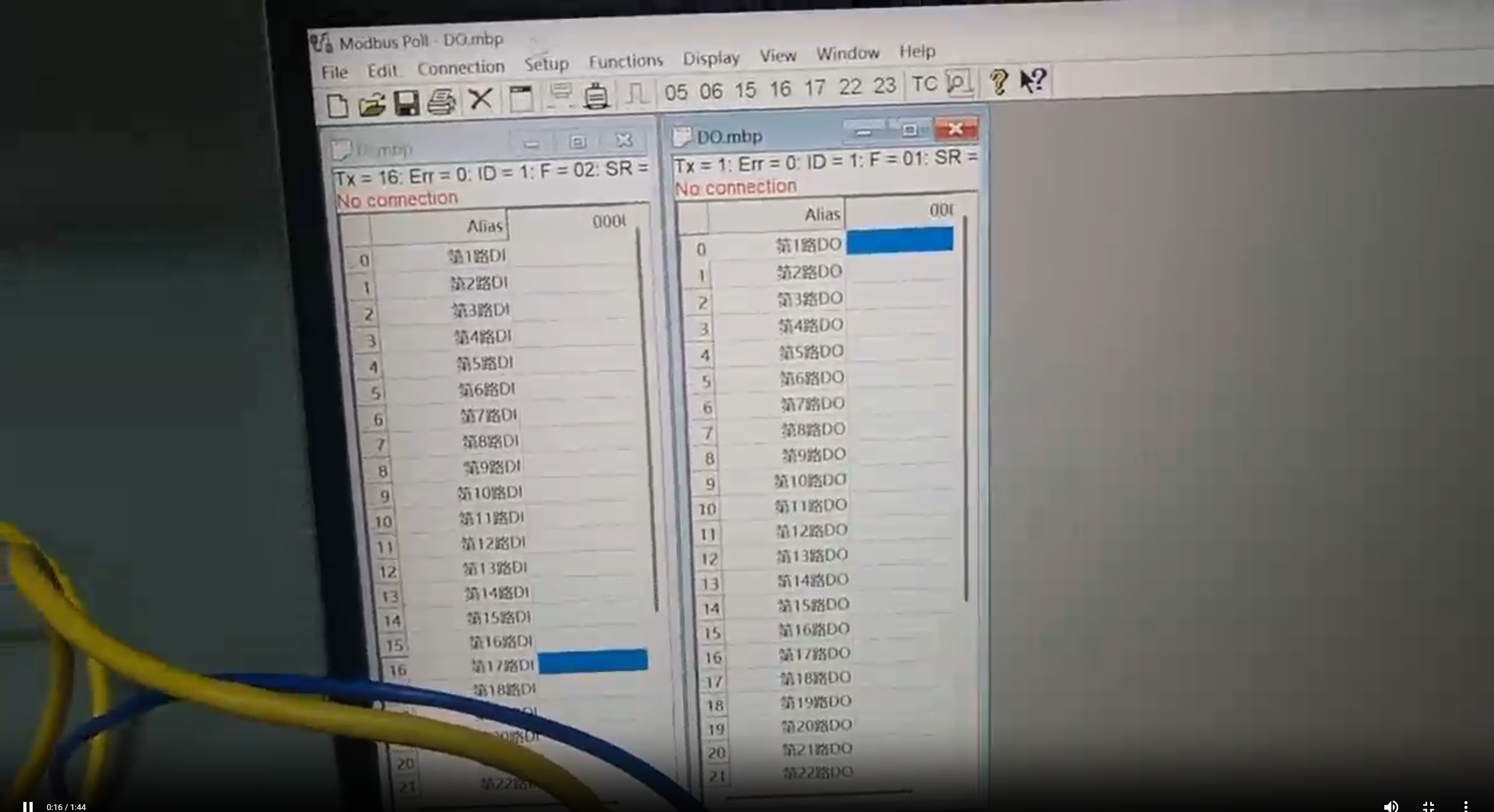
이미지 출처 : STM32 - Network Communication 32-Channel DIDO Control Board - Hard Innovation Society
Where WIZnet Fits
이 시스템에서 W5500은 STM32와 Ethernet 네트워크 사이의 TCP/IP 통신을 담당하는 Ethernet Controller입니다.
W5500에는 Ethernet MAC/PHY와 하드웨어 TCP/IP 기능이 포함되어 있으며, STM32F103VCT6과는 SPI 인터페이스로 연결됩니다. TCP 연결 상태, 소켓, 송수신 버퍼와 같은 네트워크 기능을 W5500 내부에서 처리하기 때문에 STM32는 현장 I/O와 Modbus 애플리케이션 로직에 집중할 수 있습니다.
역할을 구분하면 다음과 같습니다.
W5500
Ethernet 물리 링크 처리
TCP/IP 프로토콜 처리
TCP 소켓 관리
송수신 버퍼 관리
SPI를 통한 STM32와의 데이터 교환
STM32F103VCT6
32채널 디지털 입력 상태 확인
32채널 릴레이 출력 제어
Modbus 요청 해석
Modbus 데이터와 실제 I/O 연결
W5500 통신 제어
따라서 W5500은 단순히 RJ45 커넥터를 연결하기 위한 부품이 아니라, Modbus TCP 요청과 응답이 이동하는 Ethernet/TCP 전송 계층을 구성합니다.
특히 이 프로젝트처럼 64개의 디지털 I/O를 동시에 관리해야 하는 장치에서는 네트워크 처리와 I/O 제어를 분리하는 구조가 유용합니다. STM32가 TCP/IP 프로토콜 자체를 모두 처리하는 대신 W5500의 하드웨어 소켓을 사용할 수 있기 때문에 펌웨어 구조를 비교적 명확하게 유지할 수 있습니다.
Implementation Notes
공개된 프로젝트 자료에서 확인되는 주요 구성은 다음과 같습니다.
MCU: STM32F103VCT6
Ethernet Controller: WIZnet W5500
Network Protocol: Modbus TCP
Default IP: 192.168.0.8
Digital Input: 32채널
Relay Output: 32채널
Power Input: DC 9~36V
Modbus TCP 클라이언트가 보드에 요청을 보내면 W5500이 TCP 데이터를 수신하고 STM32로 전달합니다. STM32는 요청 내용을 해석한 뒤 해당 I/O 상태를 읽거나 릴레이를 변경하고, 처리 결과를 다시 W5500을 통해 네트워크로 반환합니다.
논리적으로는 디지털 입력을 읽기 전용 데이터 영역에, 릴레이 출력을 읽기와 쓰기가 가능한 데이터 영역에 연결할 수 있습니다. 일반적인 Modbus 설계에서는 DI를 Discrete Input, DO를 Coil 형태로 구성할 수 있습니다.
다만 공개 페이지에서 실제 Modbus 주소, Function Code, 채널별 Register 또는 Coil 매핑은 확인되지 않습니다. 따라서 임의의 주소를 원작 프로젝트의 설정처럼 제시할 수는 없습니다.
W5500과 STM32 사이의 구체적인 SPI 핀 배치 역시 공개 페이지에서 확인되지 않습니다. W5500은 기본적으로 SCLK, MOSI, MISO, CS 신호를 사용하지만 실제 GPIO 번호는 원본 회로도를 기준으로 확인해야 합니다.
또한 공개 자료는 HEX 펌웨어와 사용 파일 중심으로 제공되며, 실제 C 소스코드는 확인되지 않습니다. 따라서 다음 항목 역시 원본 펌웨어를 확인하지 않고 단정할 수 없습니다.
W5500 초기화 순서
SPI 동작 속도
사용 소켓 번호
Socket Buffer 할당
TCP 연결 Timeout
연결 종료 후 Socket 재생성 방식
Modbus 요청 처리 루프
Watchdog 및 통신 장애 복구 방식
소스코드가 공개되지 않은 상태에서 이러한 구현을 임의의 코드로 재작성하면 실제 프로젝트와 다른 내용이 될 수 있으므로, 여기서는 확인 가능한 아키텍처만 다룹니다.
Practical Tips / Pitfalls
기본 IP 충돌을 확인해야 합니다. 출하 또는 테스트 설정이 192.168.0.8이라면 같은 네트워크에 동일한 주소를 가진 장치가 없어야 합니다.
Ethernet Link와 Modbus TCP 상태를 분리해서 점검하는 것이 좋습니다. RJ45 Link가 정상이어도 IP 설정, TCP 세션 또는 Modbus 요청에 문제가 있으면 실제 I/O 제어는 동작하지 않습니다.
SPI 배선은 반드시 실제 회로도를 기준으로 확인해야 합니다. W5500의 SCLK, MOSI, MISO, CS뿐 아니라 Reset과 Interrupt 사용 여부도 함께 확인하는 것이 좋습니다.
I/O 주소 매핑을 명확하게 문서화해야 합니다. 32개의 입력과 출력이 각각 어떤 Modbus 주소에 대응하는지 정리되어 있어야 PLC와 HMI 프로그램을 안정적으로 구성할 수 있습니다.
TCP 연결 복구를 고려해야 합니다. Ethernet 케이블 분리, 스위치 재부팅, PLC 재접속 이후에도 W5500 Socket이 비정상 상태로 남지 않도록 연결 상태를 감시해야 합니다.
릴레이 부하는 MCU 회로와 별도로 검토해야 합니다. 고전압 또는 대전류 부하를 연결할 경우 릴레이 접점 정격뿐 아니라 배선 규격, 절연 거리, 보호 소자와 차단 방법을 함께 고려해야 합니다.
FAQ
Q1. 이 프로젝트에서 왜 W5500을 사용하나요?
W5500은 Ethernet MAC/PHY와 TCP/IP 기능을 하드웨어에서 처리하고 STM32에는 SPI 기반 Socket 인터페이스를 제공합니다. STM32는 네트워크 프로토콜 처리보다 32개의 입력 감시, 32개의 릴레이 제어, Modbus 요청 처리에 집중할 수 있습니다. 많은 I/O를 동시에 관리하는 제어 장치에서 네트워크와 제어 로직의 역할을 분리하기 위한 구성입니다.
Q2. W5500은 STM32F103VCT6과 어떻게 연결되나요?
SPI 인터페이스를 사용합니다. 기본적으로 SCLK, MOSI, MISO, CS 신호가 필요하며 설계에 따라 Reset과 Interrupt 신호를 추가할 수 있습니다. 이 프로젝트에서 사용한 실제 STM32 GPIO 번호는 공개 자료에서 확인되지 않으므로 회로도를 기준으로 확인해야 합니다.
Q3. W5500은 이 프로젝트에서 정확히 무엇을 담당하나요?
Modbus TCP 데이터가 이동하는 Ethernet과 TCP 통신 경로를 담당합니다. 외부 클라이언트가 보낸 TCP 데이터를 STM32에 전달하고, STM32가 생성한 Modbus 응답을 다시 Ethernet으로 전송합니다. 실제 입력 상태 판단과 릴레이 ON/OFF 제어는 STM32가 담당합니다.
Q4. 초보자도 이 프로젝트를 따라 할 수 있나요?
완성된 보드를 Modbus TCP 장치로 사용하는 것은 비교적 접근하기 쉽지만 펌웨어를 직접 개발하려면 STM32 GPIO, SPI, IPv4, TCP Socket과 Modbus 데이터 모델을 이해해야 합니다. 특히 64채널 I/O 매핑과 Ethernet 연결 장애 복구까지 직접 구현하려면 기본적인 임베디드 네트워크 개발 경험이 필요합니다.
Q5. 32개의 DI와 32개의 DO는 Modbus에서 어떻게 다루나요?
일반적인 Modbus 설계에서는 디지털 입력을 Discrete Input으로, 릴레이 출력을 Coil로 매핑할 수 있습니다. 하지만 이 프로젝트가 실제로 사용한 주소 범위와 Function Code는 공개 페이지에서 확인되지 않으므로 제공되는 명령 설명 자료 또는 펌웨어 문서를 기준으로 확인해야 합니다.
Project Overview
This project is an industrial Ethernet I/O board based on the STM32F103VCT6, designed to monitor 32 digital input (DI) channels and remotely control 32 relay output (DO) channels. The network interface uses the WIZnet W5500, allowing Modbus TCP clients such as PCs, HMIs, and PLCs to read field signals or control relays over Ethernet.
The overall architecture can be divided into input and output data paths.
Input
Sensors / Switches → 32 DI → STM32F103VCT6 → W5500 → Ethernet → Modbus TCP Client
Output
Modbus TCP Client → Ethernet → W5500 → STM32F103VCT6 → 32 Relay DO → Field Loads
The STM32F103VCT6 monitors the actual digital input states and controls the relay outputs, while the W5500 provides the TCP/IP communication path to the external network.
The default network address is configured as the static IP 192.168.0.8. The board operates from a DC 9–36 V power supply, and according to the original project, the relay contacts are rated for loads up to 220 V / 10 A.
This architecture is suitable for factory automation environments where multiple sensors and contact outputs need to be consolidated into a single Ethernet node. Instead of running long local wiring directly to a PLC or HMI, the I/O board can be installed close to the field devices, while monitoring and output control are performed remotely through Modbus TCP.
Image source: STM32 - Network Communication 32-Channel DIDO Control Board - Hard Innovation Society
Where WIZnet Fits
In this system, the W5500 serves as the Ethernet controller responsible for TCP/IP communication between the STM32 and the Ethernet network.
The W5500 integrates an Ethernet MAC/PHY and hardware TCP/IP functions and connects to the STM32F103VCT6 through an SPI interface. Because network functions such as TCP connection states, sockets, and transmit/receive buffers are handled inside the W5500, the STM32 can focus on field I/O control and Modbus application logic.
The responsibilities can be divided as follows.
W5500
Handles the Ethernet physical link
Processes TCP/IP protocols
Manages TCP sockets
Manages transmit and receive buffers
Exchanges data with the STM32 over SPI
STM32F103VCT6
Monitors 32 digital input channels
Controls 32 relay output channels
Interprets Modbus requests
Maps Modbus data to physical I/O
Controls communication with the W5500
The W5500 is therefore more than a component used to connect an RJ45 connector. It forms the Ethernet/TCP transport layer through which Modbus TCP requests and responses are exchanged.
This separation between network processing and I/O control is particularly useful in a device that must manage 64 digital I/O channels simultaneously. Instead of requiring the STM32 to handle the entire TCP/IP protocol stack itself, the firmware can use the W5500 hardware socket interface, helping keep the firmware architecture relatively clear and manageable.
Implementation Notes
The main configuration confirmed from the publicly available project materials is as follows.
MCU: STM32F103VCT6
Ethernet Controller: WIZnet W5500
Network Protocol: Modbus TCP
Default IP: 192.168.0.8
Digital Input: 32 channels
Relay Output: 32 channels
Power Input: DC 9–36 V
When a Modbus TCP client sends a request to the board, the W5500 receives the TCP data and forwards it to the STM32. The STM32 interprets the request, reads the corresponding I/O state or changes a relay output, and then returns the result over the network through the W5500.
From a logical perspective, digital inputs can be mapped to read-only data areas, while relay outputs can be mapped to data areas that support both reading and writing. In a typical Modbus implementation, DIs can be represented as Discrete Inputs and DOs as Coils.
However, the publicly available project page does not provide the actual Modbus addresses, Function Codes, or channel-specific Register/Coil mappings. Therefore, arbitrary addresses should not be presented as if they were part of the original project configuration.
The exact SPI pin mapping between the W5500 and STM32 is also not available on the public project page. The W5500 normally uses SCLK, MOSI, MISO, and CS signals, but the actual GPIO assignments must be confirmed from the original schematic.
The publicly available materials mainly include HEX firmware and usage files, while the actual C source code is not provided. As a result, the following implementation details cannot be confirmed without access to the original firmware source:
W5500 initialization sequence
SPI operating frequency
Socket number assignment
Socket buffer allocation
TCP connection timeout
Socket recreation after connection termination
Modbus request processing loop
Watchdog and communication recovery behavior
Recreating these functions with arbitrary code while the original source is unavailable could result in an implementation that differs from the actual project. For that reason, this article focuses only on the architecture that can be verified from the available materials.
Practical Tips / Pitfalls
Check for default IP address conflicts. If the board is shipped or tested with 192.168.0.8, make sure no other device on the same network is using the same address.
Check the Ethernet link and Modbus TCP connection separately. A valid RJ45 link does not necessarily mean that I/O control is working. Incorrect IP settings, TCP session problems, or invalid Modbus requests can still prevent communication.
Verify SPI wiring against the actual schematic. In addition to SCLK, MOSI, MISO, and CS, check whether the design also uses the W5500 Reset and Interrupt signals.
Document the I/O address mapping clearly. Each of the 32 inputs and 32 outputs should have a clearly defined Modbus address so that PLC and HMI applications can communicate with the board reliably.
Plan for TCP connection recovery. The firmware should monitor the socket state so that the W5500 does not remain in an invalid state after events such as Ethernet cable disconnection, network switch reboot, or PLC reconnection.
Evaluate relay loads separately from the MCU circuitry. When switching high-voltage or high-current loads, consider not only the relay contact rating but also wire sizing, insulation distance, protection components, and circuit interruption methods.
FAQ
Q1. Why is the W5500 used in this project?
The W5500 handles the Ethernet MAC/PHY and TCP/IP functions in hardware and provides the STM32 with an SPI-based socket interface. This allows the STM32 to focus on monitoring 32 inputs, controlling 32 relays, and processing Modbus requests instead of handling network protocols directly. The architecture separates network communication from control logic in a device that manages a large number of I/O channels.
Q2. How is the W5500 connected to the STM32F103VCT6?
It uses an SPI interface. SCLK, MOSI, MISO, and CS signals are required, while Reset and Interrupt signals can also be used depending on the design. The exact STM32 GPIO assignments used in this project are not available in the public materials, so they should be confirmed from the schematic.
Q3. What exactly does the W5500 do in this project?
The W5500 provides the Ethernet and TCP communication path used to transport Modbus TCP data. It forwards TCP data received from an external client to the STM32 and sends the Modbus response generated by the STM32 back over Ethernet. The STM32 itself is responsible for evaluating input states and controlling the relay outputs.
Q4. Can beginners follow this project?
Using the completed board as a Modbus TCP device is relatively straightforward. However, developing the firmware from scratch requires an understanding of STM32 GPIO, SPI, IPv4, TCP sockets, and the Modbus data model. Implementing 64-channel I/O mapping and Ethernet connection recovery also benefits from basic embedded networking experience.
Q5. How are the 32 DIs and 32 DOs handled in Modbus?
In a typical Modbus design, digital inputs can be mapped as Discrete Inputs, while relay outputs can be mapped as Coils. However, the actual address ranges and Function Codes used by this project are not available on the public project page. They should therefore be confirmed using the provided command documentation or firmware documentation.


