


Inoa Satellite Gateway
Inoa Satellite Gateway

WIZnet - W5500
x 1

Espressif - ESP32
x 1
프로젝트 개요
INOA Satellite는 전력계, 센서, 산업 설비에서 데이터를 수집해 상위 IoT 시스템으로 전달하는 ESP32 기반 모듈형 DIN-rail 게이트웨이입니다. 특정 센서 하나에 종속된 장치가 아니라 RS485/Modbus, M-Bus, Pulse, CT 등 다양한 계측 인터페이스와 여러 네트워크 방식을 조합할 수 있도록 설계되어 있습니다.
하드웨어는 기능별로 계층을 나누는 구조입니다.
전력계 / 센서 / 산업 설비
        │
        │ RS485 · Modbus · M-Bus · Pulse · CT
        ▼
Level 1 — 계측 및 I/O
        │
        ▼
Level 2 — ESP32 · ATECC608 · Flash · microSD
        │
        │ SPI
        ▼
Level 3 — WIZnet W5500 Ethernet
        │
        ▼
현장 LAN / Internet
        │
        ▼
INOA Cloud
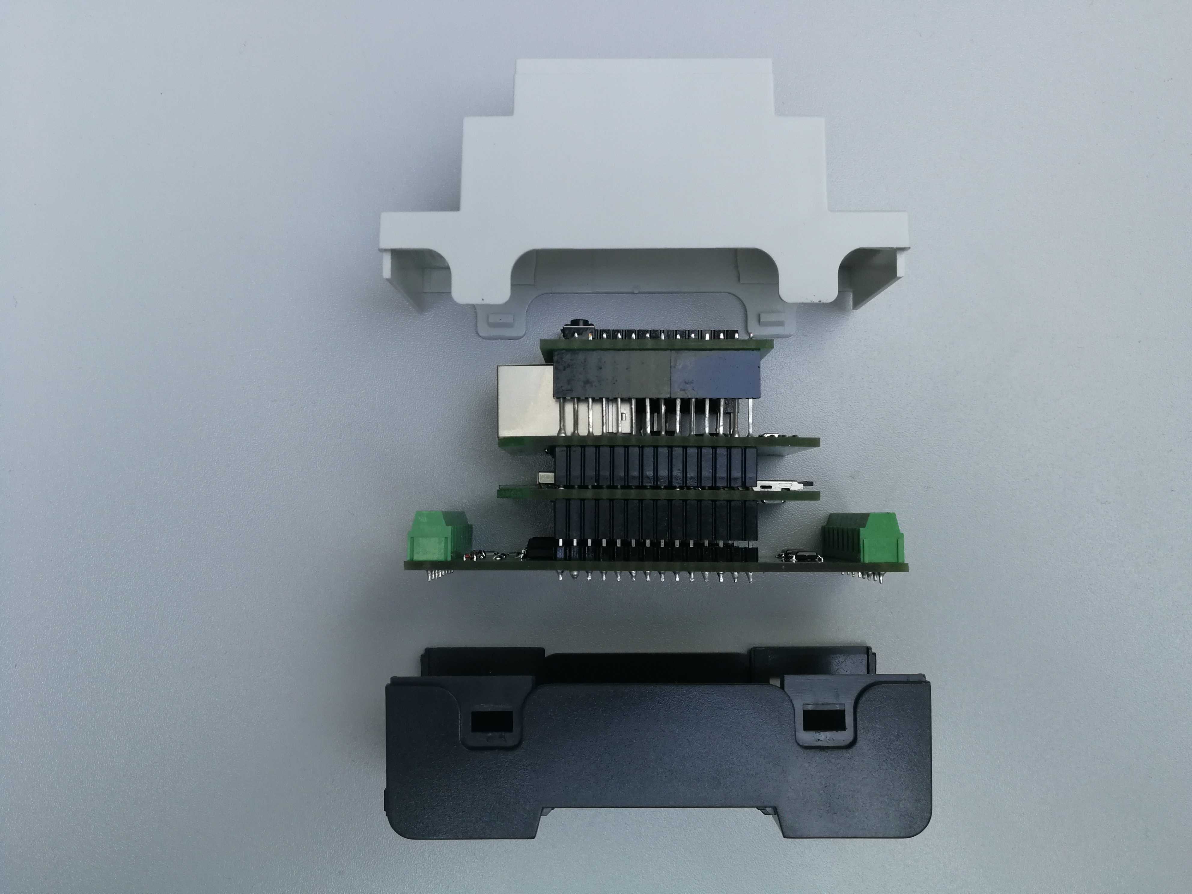
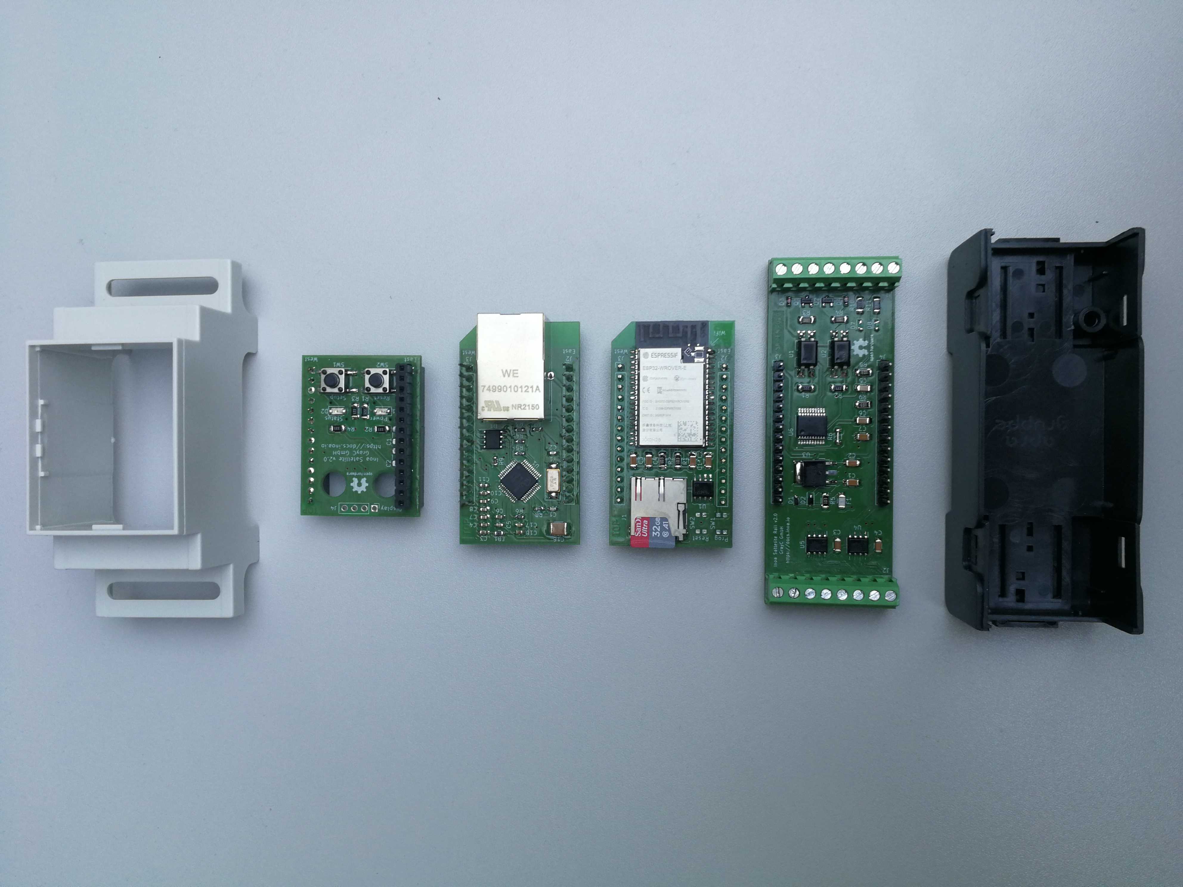
이미지 출처 : https://inoa-io.github.io/satellite/
Level 1은 현장 장치와 연결되는 계측 계층입니다. RS485/Modbus, M-Bus, 펄스 입력, CT 입력 등 필요한 인터페이스를 모듈 형태로 구성합니다.
Level 2는 ESP32가 위치하는 연산 계층입니다. 수집한 데이터를 처리하고 장치를 제어하며, ATECC608 보안 칩과 Flash, microSD 같은 저장장치를 사용할 수 있도록 설계되어 있습니다.
Level 3은 네트워크 계층입니다. Ethernet, NB-IoT, LoRa처럼 설치 환경에 맞는 통신 방식을 선택할 수 있으며, 공개된 Ethernet Extension에서는 WIZnet W5500을 사용합니다.
Level 4는 LED, 버튼, 디버그 인터페이스 등 설치와 유지보수를 위한 사용자 인터페이스 계층입니다.
이 구조의 특징은 계측, 연산, 네트워크 기능을 하나의 PCB에 고정하지 않았다는 점입니다. 예를 들어 Ethernet 대신 다른 통신 방식을 적용하더라도 계측 보드와 ESP32 메인 보드 전체를 다시 설계할 필요가 없습니다.
INOA는 어떤 일을 하나요?
inoa-io는 INOA 프로젝트의 GitHub 조직이며, 공개 자료에서는 독일 GrayC GmbH가 INOA IoT 플랫폼을 개발하고 있는 것으로 확인됩니다.
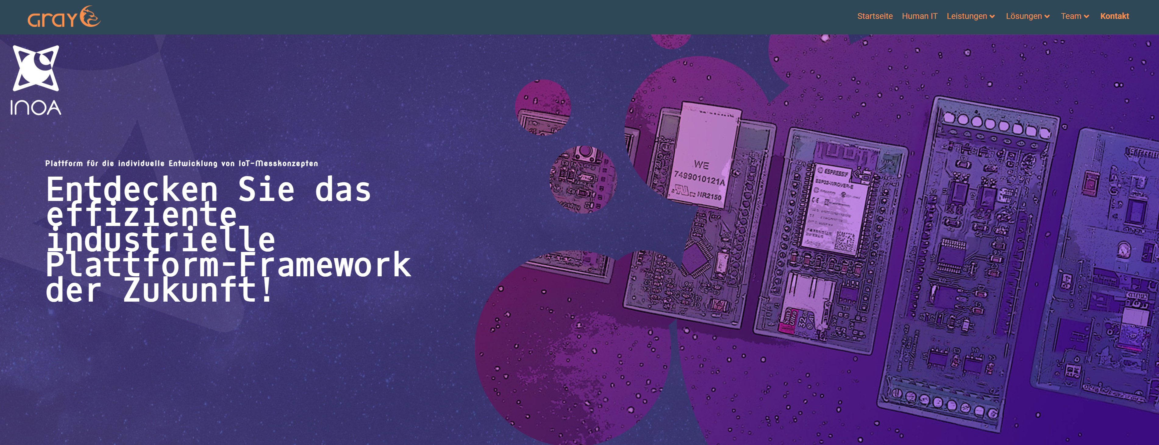
이미지 출처 : https://www.grayc.de/
GrayC는 소프트웨어 개발, 클라우드 인프라, IoT 시스템, 디바이스 관리 등을 다루고 있으며, INOA는 현장 데이터 수집부터 장치 운영과 데이터 관리까지 연결하는 IoT 제품군으로 구성되어 있습니다.
주요 구성 요소는 다음과 같습니다.
Satellite: 센서와 계측 장치에서 데이터를 수집하는 현장 게이트웨이
INOA OS: 장치에서 데이터 수집과 전송을 담당하는 소프트웨어 계층
Fleet: 장치 등록, 설정, 상태 확인, 업데이트 관리
Measurement: 수집된 데이터를 저장하고 처리하는 계층
GroundControl: 설치와 운영을 위한 관리 인터페이스
따라서 Satellite는 단독으로 동작하는 Ethernet 보드라기보다, 현장 계측 장치를 상위 IoT 시스템과 연결하는 Edge Gateway로 보는 것이 적절합니다.
WIZnet W5500은 어디에 사용되나요?
Satellite에서 W5500은 ESP32와 유선 LAN 사이의 Ethernet 인터페이스를 담당합니다.
전체 데이터 흐름을 단순화하면 다음과 같습니다.
센서 / 미터
   ↓
RS485 · M-Bus · CT · Pulse
   ↓
ESP32
   ↓
W5500
   ↓
Ethernet
   ↓
상위 IoT 시스템
W5500이 Modbus 데이터나 센서 값을 직접 해석하는 것은 아닙니다. 현장 데이터는 먼저 ESP32에서 처리되고, W5500은 ESP32가 유선 Ethernet 네트워크를 사용할 수 있도록 연결 경로를 제공합니다.
Satellite에서는 이 Ethernet 기능을 별도의 Level 3 보드로 분리했습니다. 네트워크 기능을 메인 PCB에 고정하지 않았기 때문에 설치 환경에 따라 Ethernet이나 다른 통신 방식을 선택하기 쉽습니다.
W5500은 10/100 Ethernet MAC/PHY와 Hardwired TCP/IP 기능을 제공하며 SPI로 MCU와 연결할 수 있습니다. 최대 8개의 하드웨어 소켓과 32 KB의 내부 송수신 버퍼도 제공합니다.
이러한 구조는 MCU의 네트워크 처리 부담을 줄이는 데 활용할 수 있습니다. 다만 Satellite 공개 저장소에서는 실제 네트워크 애플리케이션 펌웨어가 확인되지 않으므로, 이 프로젝트가 W5500의 하드웨어 TCP/IP 소켓을 실제로 어떤 방식으로 활용하는지는 공개 자료만으로 판단할 수 없습니다.
구현 메모
W5500은 실제 Ethernet PCB에 포함되어 있습니다
Satellite 저장소의 Ethernet Extension 회로도에는 W5500이 실제 부품으로 정의되어 있습니다.
파일:
electrics/ethernet-extension/ethernet-extension.kicad_sch
(symbol "Interface_Ethernet:W5500"
(property "Value" "W5500")
이 정의를 통해 W5500이 README에서 단순히 추천되는 부품이 아니라 Ethernet Extension PCB의 실제 Ethernet 컨트롤러라는 점을 확인할 수 있습니다.
같은 보드에는 Ethernet 커넥터와 ESD 보호 회로도 포함되어 있습니다. 따라서 Satellite의 Ethernet Extension은 개발용 W5500 모듈을 단순히 연결한 형태가 아니라, 네트워크 인터페이스를 하나의 독립된 PCB로 설계한 구조입니다.
ESP32와 W5500은 SPI로 연결됩니다
프로젝트에서 공개한 핀 정의에는 Ethernet 인터페이스가 다음과 같이 배치되어 있습니다.
GPIO34 → SPI2 MISO
GPIO32 → SPI2 MOSI
GPIO33 → SPI2 CLK
GPIO27 → Ethernet CS
GPIO14 → Ethernet Reset
GPIO4  → Ethernet Interrupt
W5500은 ESP32의 SPI2 장치로 구성되어 있습니다.
MISO, MOSI, CLK, CS 외에도 Reset과 Interrupt 신호가 따로 연결되어 있습니다. 이를 통해 펌웨어에서 W5500의 상태를 확인하거나 Ethernet 컨트롤러만 별도로 재초기화하는 구조를 구현할 수 있습니다.
microSD는 별도의 SPI 버스를 사용합니다. 따라서 저장장치와 Ethernet 인터페이스가 동일한 SPI 버스의 설정이나 통신 상태에 서로 영향을 주지 않도록 구성되어 있습니다.
실전 팁 / 주의점
SPI 버스 구성을 먼저 확인하시는 것이 좋습니다. 원본 Satellite에서는 W5500과 microSD가 서로 다른 SPI 버스를 사용합니다. 하나의 버스로 통합할 경우 CS와 SPI 설정 전환을 별도로 관리해야 합니다.
Reset과 Interrupt 신호를 활용하는 것이 좋습니다. 원격 설치형 게이트웨이에서는 통신 장애가 발생했을 때 ESP32 전체를 재부팅하지 않고 W5500만 재초기화할 수 있는 구조가 유용합니다.
RJ45 주변 보호 회로도 함께 고려해야 합니다. 원본 Ethernet Extension에는 ESD 보호 회로가 포함되어 있습니다. 산업 설비나 분전반 환경에서는 Ethernet 커넥터가 외부 노이즈와 정전기의 유입 경로가 될 수 있습니다.
DHCP와 고정 IP 정책은 별도로 설계해야 합니다. 공개된 하드웨어 자료만으로는 Satellite가 실제 환경에서 어떤 IP 설정 방식을 사용하는지 확인할 수 없습니다.
SPI 속도는 실제 PCB에서 검증하는 것이 좋습니다. W5500 자체는 고속 SPI를 지원하지만 적층 커넥터, 배선 길이, 신호 품질을 고려해 안정적인 속도를 결정해야 합니다.
TCP/IP 처리 구조를 먼저 결정해야 합니다. W5500의 하드웨어 소켓을 직접 사용할지, 별도의 소프트웨어 네트워크 구조와 조합할지는 사용하는 펌웨어에 따라 달라집니다.
FAQ
Q1. INOA Satellite에서는 왜 W5500을 사용하나요?
Satellite는 ESP32 기반 게이트웨이에 유선 Ethernet을 추가하면서도 네트워크 기능을 독립된 모듈로 구성하고 있습니다. W5500은 SPI로 ESP32와 연결할 수 있으며 Ethernet MAC/PHY와 Hardwired TCP/IP 기능을 하나의 칩에 제공하므로 이러한 모듈형 구조에 적용하기 적합합니다.
Q2. W5500은 ESP32와 어떻게 연결되나요?
SPI2를 사용합니다. 프로젝트 핀 정의 기준으로 GPIO34가 MISO, GPIO32가 MOSI, GPIO33이 CLK, GPIO27이 CS이며, GPIO14와 GPIO4가 각각 Reset과 Interrupt에 할당되어 있습니다.
Q3. 이 프로젝트에서 W5500은 어떤 역할을 하나요?
ESP32가 처리한 계측 데이터를 유선 Ethernet 네트워크로 전달할 수 있도록 네트워크 인터페이스를 제공합니다. RS485나 M-Bus 데이터를 직접 처리하는 것이 아니라 Satellite의 상위 네트워크 연결을 담당합니다.
Q4. 초보자도 같은 구조를 구현할 수 있나요?
일반적인 Arduino용 W5500 모듈을 연결하는 것보다는 난도가 높습니다. SPI뿐 아니라 Ethernet 커넥터, ESD 보호, Reset/Interrupt 처리, 전원 설계, ESP32 네트워크 드라이버에 대한 이해가 필요합니다. 또한 공개 저장소에는 완성된 W5500 애플리케이션 펌웨어가 포함되어 있지 않아 네트워크 소프트웨어는 별도로 구성해야 합니다.
Q5. Wi-Fi와 비교했을 때 W5500 Ethernet은 어떤 경우에 적합한가요?
분전반이나 고정 설비처럼 Ethernet 케이블을 설치할 수 있는 환경에서는 유선 네트워크가 RF 간섭이나 AP 상태에 영향을 받지 않고 링크 상태를 관리하기 쉽습니다. 반대로 배선이 어렵거나 이동성이 필요한 장치에서는 Wi-Fi가 더 적합할 수 있습니다. Satellite가 네트워크 계층을 모듈화한 것도 이러한 설치 조건에 따라 통신 방식을 선택할 수 있도록 하기 위한 구조로 볼 수 있습니다.
Project Overview
INOA Satellite is an ESP32-based modular DIN-rail gateway designed to collect data from power meters, sensors, and industrial equipment and forward it to higher-level IoT systems. Rather than being tied to a single type of sensor, it supports a combination of measurement interfaces such as RS485/Modbus, M-Bus, pulse inputs, and CT inputs, along with multiple network options.
The hardware is divided into functional layers.
Power Meters / Sensors / Industrial Equipment
        │
        │ RS485 · Modbus · M-Bus · Pulse · CT
        ▼
Level 1 — Measurement and I/O
        │
        ▼
Level 2 — ESP32 · ATECC608 · Flash · microSD
        │
        │ SPI
        ▼
Level 3 — WIZnet W5500 Ethernet
        │
        ▼
Local LAN / Internet
        │
        ▼
INOA Cloud
Image source: https://inoa-io.github.io/satellite/
Level 1 is the measurement layer connected to field devices. Interfaces such as RS485/Modbus, M-Bus, pulse inputs, and CT inputs are implemented as modular options.
Level 2 is the processing layer built around the ESP32. It processes collected data, controls connected devices, and supports components such as the ATECC608 security chip, Flash memory, and microSD storage.
Level 3 is the network layer. Communication methods such as Ethernet, NB-IoT, and LoRa can be selected depending on the installation environment. The publicly available Ethernet Extension uses the WIZnet W5500.
Level 4 is the user interface layer for installation and maintenance, including LEDs, buttons, and debugging interfaces.
A key feature of this architecture is that measurement, processing, and networking functions are not fixed to a single PCB. For example, changing from Ethernet to another communication method does not require redesigning the entire measurement board or ESP32 main board.
What Does INOA Do?
inoa-io is the GitHub organization for the INOA project. Publicly available information indicates that the INOA IoT platform is developed by GrayC GmbH, a German company.
Image source: https://www.grayc.de/
GrayC works in areas including software development, cloud infrastructure, IoT systems, and device management. INOA is structured as an IoT product ecosystem that connects field data acquisition with device operation and data management.
Its main components include:
Satellite: A field gateway that collects data from sensors and measurement devices.
INOA OS: The software layer responsible for data collection and transmission on the device.
Fleet: A system for device registration, configuration, status monitoring, and update management.
Measurement: A layer for storing and processing collected measurement data.
GroundControl: A management interface for installation and operation.
Satellite is therefore better understood not as a standalone Ethernet board, but as an edge gateway that connects field measurement devices to higher-level IoT systems.
Where Is the WIZnet W5500 Used?
In Satellite, the W5500 provides the Ethernet interface between the ESP32 and the wired LAN.
The overall data flow can be simplified as follows:
Sensors / Meters
   ↓
RS485 · M-Bus · CT · Pulse
   ↓
ESP32
   ↓
W5500
   ↓
Ethernet
   ↓
Higher-Level IoT System
The W5500 does not directly interpret Modbus data or sensor values. Field data is first processed by the ESP32, while the W5500 provides the network path that allows the ESP32 to communicate over wired Ethernet.
Satellite separates this Ethernet functionality into an independent Level 3 board. Because the network interface is not fixed to the main PCB, Ethernet or other communication methods can be selected depending on the installation environment.
The W5500 provides a 10/100 Ethernet MAC/PHY and Hardwired TCP/IP functionality and connects to the MCU through SPI. It also provides up to eight hardware sockets and 32 KB of internal TX/RX buffer memory.
This architecture can be used to reduce the amount of network processing handled directly by the MCU. However, the public Satellite repository does not include the actual network application firmware. Therefore, the available public sources are not sufficient to determine exactly how the project uses the W5500 hardware TCP/IP sockets in practice.
Implementation Notes
The W5500 Is Included on the Actual Ethernet PCB
The Ethernet Extension schematic in the Satellite repository defines the W5500 as an actual hardware component.
File:
electrics/ethernet-extension/ethernet-extension.kicad_sch
(symbol "Interface_Ethernet:W5500"
(property "Value" "W5500")
This confirms that the W5500 is not simply a component recommended in the README. It is the actual Ethernet controller used on the Ethernet Extension PCB.
The same board also includes an Ethernet connector and ESD protection circuitry. The Satellite Ethernet Extension is therefore designed as a complete, independent network interface PCB rather than as a simple connection to an off-the-shelf W5500 development module.
The ESP32 and W5500 Are Connected via SPI
The published project pinout defines the Ethernet interface as follows:
GPIO34 → SPI2 MISO
GPIO32 → SPI2 MOSI
GPIO33 → SPI2 CLK
GPIO27 → Ethernet CS
GPIO14 → Ethernet Reset
GPIO4  → Ethernet Interrupt
The W5500 is configured as an SPI2 device on the ESP32.
In addition to MISO, MOSI, CLK, and CS, separate Reset and Interrupt signals are provided. This allows the firmware to monitor the W5500 status or reinitialize the Ethernet controller independently when necessary.
The microSD interface uses a separate SPI bus. This arrangement prevents the storage device and Ethernet interface from depending on the same SPI bus configuration or communication state.
Practical Tips / Pitfalls
Check the SPI bus configuration first. In the original Satellite design, the W5500 and microSD use separate SPI buses. If they are combined onto a single bus in a custom design, chip-select handling and SPI configuration switching must be managed separately.
Use the Reset and Interrupt signals where possible. In remotely installed gateways, it can be useful to recover from a communication failure by reinitializing only the W5500 instead of rebooting the entire ESP32.
Consider the protection circuitry around the RJ45 connector. The original Ethernet Extension includes ESD protection. In industrial equipment or distribution panels, the Ethernet connector can become an entry point for external electrical noise and electrostatic discharge.
Define the DHCP and static IP policy separately. The publicly available hardware documentation does not show which IP configuration method Satellite uses in deployed systems.
Validate the SPI clock speed on the actual PCB. Although the W5500 supports high-speed SPI communication, a stable operating frequency should be selected based on the stacking connectors, trace length, and signal integrity of the final PCB.
Decide how TCP/IP processing will be handled. Whether the application directly uses the W5500 hardware sockets or combines the device with another software networking architecture depends on the firmware design.
FAQ
Q1. Why does INOA Satellite use the W5500?
Satellite requires wired Ethernet for an ESP32-based gateway while keeping the network interface as an independent module. The W5500 connects to the ESP32 through SPI and integrates Ethernet MAC/PHY and Hardwired TCP/IP functionality in a single chip, making it suitable for this modular architecture.
Q2. How is the W5500 connected to the ESP32?
It uses SPI2. According to the project pinout, GPIO34 is used for MISO, GPIO32 for MOSI, GPIO33 for CLK, and GPIO27 for CS. GPIO14 and GPIO4 are assigned to Reset and Interrupt, respectively.
Q3. What role does the W5500 play in this project?
The W5500 provides the network interface that allows measurement data processed by the ESP32 to be transmitted over wired Ethernet. It does not directly process RS485 or M-Bus data; instead, it handles the upper-level network connection for Satellite.
Q4. Can beginners implement the same architecture?
It is more complex than connecting a typical Arduino W5500 module. Developers need to understand SPI communication, Ethernet connectors, ESD protection, Reset and Interrupt handling, power design, and ESP32 network drivers. The public repository also does not include a complete W5500 application firmware implementation, so the network software must be configured separately.
Q5. When is W5500 Ethernet more suitable than Wi-Fi?
In fixed installations such as distribution panels or industrial equipment, wired Ethernet is easier to manage because it does not depend on RF interference or access point conditions, and the physical link status can be monitored directly. Wi-Fi may be more appropriate where cabling is difficult or mobility is required. Satellite's modular network layer allows the communication method to be selected according to these installation requirements.
-
Github H/W


