
W5500_Ethernet_Driver_for_ESP32_ESP_IDF
W5500_Ethernet_Driver_for_ESP32_ESP_IDF

WIZnet - W5500
x 1
Espressif - ESP32
x 1
프로젝트 개요
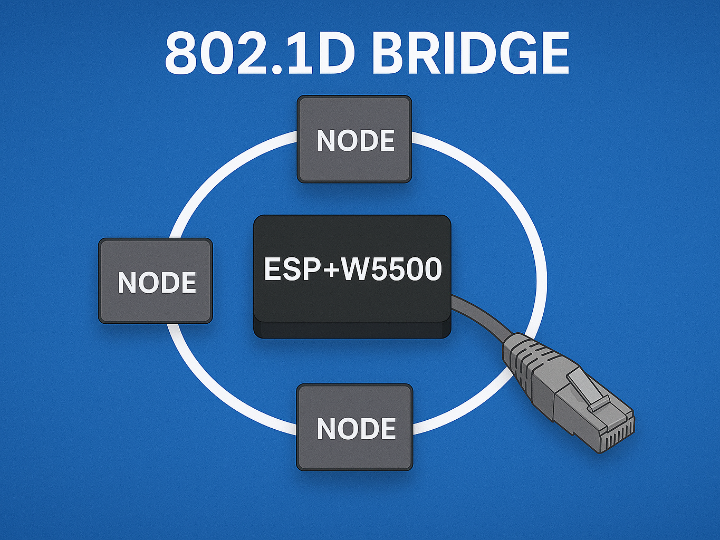
이 GitHub 예제는 IEEE 802.1D 브리지를 기반으로, ESP32를 이용해 레이어 2(L2) 브리지를 구현하는 방법을 보여주는 샘플입니다.
브리지는 두 개의 독립된 네트워크를 하나의 2계층 네트워크처럼 보이도록 연결해 주며, 특히 IoT 환경의 이더넷 기반 장치들을 체인처럼 연결(daisy-chain) 하고 싶을 때 매우 유용합니다.
원본 링크 : https://github.com/MouNir9944/W5500_Ethernet_Driver_for_ESP32_ESP_IDF
왜 브리지와 링 토폴로지가 중요한가?
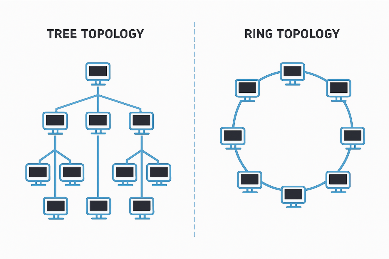
일반적인 네트워크 구성에서는 보통 트리(Tree) 토폴로지를 사용합니다.
각 장치는 중앙 스위치/라우터에 별도의 케이블로 연결됩니다.
장치 수가 많아질수록 배선이 복잡해지고 비용이 증가합니다.
반면, 이 예제가 보여주는 링(Ring) 또는 데이지 체인 구조는 다음과 같은 장점이 있습니다.
장치들이 직렬로 연결되면서, 중간 장치들이 트래픽을 다음 장치로 전달(Forwarding)
“완전한 링”이 아니더라도, 단순 체인 구조만으로도 배선 길이와 복잡도 감소
ESP32를 소프트웨어 기반 브리지로 사용함으로써, IoT 노드들을 서로 브리지하고
단순한 하드웨어 구성만으로 유연한 네트워크 토폴로지를 만들 수 있습니다.
ESP32 소프트웨어 브리지 성능 한계
이 예제는 소프트웨어 브리지 방식이므로, 성능은 다음 요소에 의해 제한됩니다.
ESP32 자체의 CPU 성능
ESP32와 이더넷 PHY/모듈 간 데이터 버스 대역폭
예: 여러 개의 Ethernet 모듈이 공유하는 SPI 인터페이스
예제 구성 – 기본 브리지 설정 2가지.
예제 1 – 이더넷 ↔ 이더넷 브리지 (DHCP 클라이언트)
구성
PC#1: DHCP 서버
PC#2: DHCP 클라이언트
ESP32: 두 이더넷 포트를 PC#1, PC#2 쪽 네트워크에 연결
동작
ESP32에 이더넷 포트 초기화
브리지 설정
ESP32와 PC#2가 DHCP로 IP 할당
PC#1 ↔ ESP32, PC#1 ↔ PC#2 간 상호 Ping 가능

이미지 출처 : https://github.com/MouNir9944/W5500_Ethernet_Driver_for_ESP32_ESP_IDF
예제 2 – 이더넷 ↔ Wi-Fi AP 브리지 (DHCP 서버)
구성
ESP32: 이더넷 + Wi-Fi AP 활성화
PC#1, PC#2: DHCP 클라이언트
ESP32 menuconfig에서 DHCP 서버 옵션 활성화
동작
ESP32에 이더넷 포트와 Wi-Fi AP 초기화
브리지 설정 (이더넷 ↔ Wi-Fi)
PC#1, PC#2가 ESP32 DHCP 서버에서 IP 할당
PC#1 ↔ ESP32, PC#1 ↔ PC#2 간 상호 Ping 가능

이미지 출처 : https://github.com/MouNir9944/W5500_Ethernet_Driver_for_ESP32_ESP_IDF
Application
산업용·임베디드 장비의 링/데이지 체인 이더넷 노드
Wi-Fi AP ↔ Ethernet 브리지, 무선–유선 통합
투명 브리지로 네트워크 세그먼트 확장·연결
패킷 캡처/모니터링용 TAP·스니퍼 장비
왜 대부분의 네트워크는 트리 구조를 사용할까?
관리 쉬움
트리는 고장 난 장치를 바로 찾기 쉽지만, 링은 문제 위치 찾기가 어렵다.
장비 호환성 좋음
대부분의 네트워크 장비는 트리 구조를 기준으로 만들어져 있다.
안정적인 트래픽
트리는 루프 문제가 적지만, 링은 잘못 구성하면 장애가 쉽게 생긴다.
확장 쉬움
트리는 장치 추가가 간단하지만, 링은 체인을 끊고 다시 연결해야 해 번거롭다.
Project Overview
This GitHub example demonstrates how to implement a Layer 2 (L2) bridge on the ESP32 using the IEEE 802.1D bridging protocol.
A bridge connects two independent networks and makes them operate as a single Layer 2 segment. This is especially useful in IoT environments where Ethernet-based devices need to be linked in a daisy-chain configuration.
Original link: https://github.com/MouNir9944/W5500_Ethernet_Driver_for_ESP32_ESP_IDF
Why Are Bridges and Ring Topologies Important?
Most traditional networks use a tree topology, where each device connects directly to a central switch or router using separate cables. As the number of devices increases, cabling becomes more complex and costly.
In contrast, the ring (or daisy-chain) topology used in this example provides several advantages:
Devices are connected in series, allowing intermediate nodes to forward traffic to the next device.
Even without forming a complete ring, a simple chained layout significantly reduces cabling complexity.
By using the ESP32 as a software-based bridge, IoT nodes can be interconnected with flexible network layouts while keeping hardware requirements minimal.
Limitations of ESP32 Software Bridging
Because this is a software bridge, its performance depends on:
The processing capability of the ESP32 CPU
The bandwidth of the data bus between the ESP32 and Ethernet PHY/modules
Example: multiple SPI-based Ethernet modules sharing a single SPI bus
Example Configurations – Two Basic Bridge Setups
Example 1 – Ethernet ↔ Ethernet Bridge (DHCP Client)
Configuration
PC#1: DHCP server
PC#2: DHCP client
ESP32: Two Ethernet ports connected to PC#1 and PC#2 networks
Operation
Initialize Ethernet ports on the ESP32
Configure the bridge
ESP32 and PC#2 obtain IP addresses via DHCP
PC#1 can Ping both the ESP32 and PC#2, and vice versa
Image source:
https://github.com/MouNir9944/W5500_Ethernet_Driver_for_ESP32_ESP_IDF
Example 2 – Ethernet ↔ Wi-Fi AP Bridge (DHCP Server)
Configuration
ESP32: Ethernet + Wi-Fi AP enabled
PC#1, PC#2: DHCP clients
DHCP server enabled in ESP32 menuconfig
Operation
Initialize the Ethernet port and Wi-Fi AP on the ESP32
Configure the Ethernet ↔ Wi-Fi bridge
PC#1 and PC#2 obtain IP addresses from the ESP32 DHCP server
PC#1 ↔ ESP32, PC#1 ↔ PC#2 communication via Ping is possible
Image source:
https://github.com/MouNir9944/W5500_Ethernet_Driver_for_ESP32_ESP_IDF
Application Examples
Industrial/embedded devices connected in a ring or daisy-chain Ethernet topology
Wi-Fi AP ↔ Ethernet bridge for wireless–wired integration
Transparent bridging to extend or link L2 network segments
Packet capture/sniffing equipment using a TAP-like bridge
Why Do Most Networks Prefer a Tree Topology?
Easier Management
A tree structure makes it simple to locate faulty devices or cables, while ring structures make troubleshooting more difficult.
Better Compatibility
Most network equipment—switches, routers, management systems—is designed with tree topology as the default.
More Stable Traffic
A tree has fewer risks of loops, whereas rings can easily cause broadcast storms or packet loops if not configured properly.
Simpler Expansion
New devices can be added easily by connecting them to a switch, whereas ring networks often require breaking and reconnecting the chain.
-
Github Code
