


servimetro-esp32
servimetro-esp32

WIZnet - W5500
x 1

Espressif - ESP32
x 1
프로젝트 개요
Servimetro는 ESP32-WROOM-32를 기반으로 PT100 센서의 온도를 측정하고 보정하며, Additel 875 온도 교정 장비를 유선 네트워크로 제어하는 시스템입니다.
PT100은 온도에 따라 저항값이 변하는 센서입니다. MAX31865 RTD(Resistance Temperature Detector) 변환기는 PT100의 미세한 저항 변화를 측정해 ESP32가 처리할 수 있는 디지털 온도 데이터로 변환합니다. 이를 통해 센서 신호를 안정적으로 읽고 배선 저항과 측정 잡음으로 인한 오차를 줄일 수 있습니다.
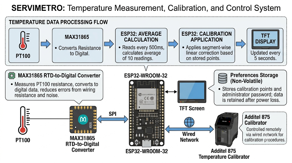
이미지 출처 : AI 생성
ESP32는 약 500밀리초마다 온도를 읽고, 측정값 10개의 평균을 계산합니다. 이후 저장된 교정점을 기준으로 구간별 선형 보정을 적용하고, 결과를 TFT 화면에 표시합니다. 보정된 온도는 약 5초마다 갱신되며, 교정점과 관리자 비밀번호는 Preferences 저장소에 보관되어 전원을 꺼도 유지됩니다.
온도 데이터는 다음 순서로 처리됩니다.
PT100 → MAX31865 → ESP32 평균 계산 → 교정값 적용 → TFT 표시
Additel 875는 설정된 목표 온도를 만들고 일정하게 유지하는 온도 교정 장비입니다. PT100을 Additel 875의 안정된 온도 환경에 놓고 기준 온도와 센서 측정값을 비교하면 센서와 측정 회로의 오차를 확인할 수 있습니다. 이 비교 결과는 교정점으로 저장되어 이후 측정값을 보정하는 데 사용됩니다.
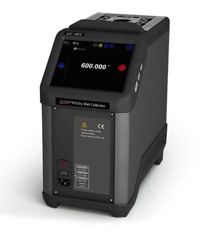
이미지 출처 : https://additel.com/
ESP32와 Additel 875는 다음 경로로 통신합니다.
ESP32 → SPI → W5500 → Ethernet TCP/8000 → Additel 875
시스템이 시작되면 ESP32는 W5500의 이더넷 링크를 확인합니다. 연결이 정상일 경우 Additel 875에 50°C 목표값을 전송하고, 이후 약 30초마다 SCPI 명령으로 장비의 제어 상태를 조회합니다.
현재 펌웨어는 Additel 875의 응답을 시리얼 모니터에 출력합니다. 응답을 분석해 TFT 화면에 표시하거나 자동 교정 절차에 반영하는 기능은 아직 구현되어 있지 않습니다.
Wi-Fi와 WiFiManager도 초기화되지만, 현재 코드에서는 설정 포털과 연결 상태 표시 용도로 사용됩니다.
활용 사례
이 프로젝트는 PT100 센서와 온도 계측 장비의 오차를 확인하고 보정해야 하는 환경에 활용할 수 있습니다.
온도 센서 교정
PT100 센서를 Additel 875의 안정적인 온도 환경에 놓고 기준 온도와 측정값을 비교할 수 있습니다. 여러 온도 구간에서 확인한 오차를 교정점으로 저장하면 실제 운전 환경에서 보정된 값을 표시할 수 있습니다.
산업용 온도 계측기 점검
생산 설비, 시험 장비, 저장 시설 등에 설치된 PT100 기반 온도 계측기의 정확도를 확인하는 데 활용할 수 있습니다. 작업자는 TFT 화면에서 측정값과 보정 결과를 확인하고 필요한 교정값을 입력할 수 있습니다.
정기 교정 작업
온도 센서와 계측기는 장기간 사용하면서 센서 열화, 배선 저항, 회로 오차 등의 영향을 받을 수 있습니다. Additel 875의 기준 온도와 PT100 측정값을 비교하면 정기적인 점검과 재교정을 수행할 수 있습니다.
계측 및 네트워크 교육
PT100의 저항 변화, MAX31865의 측정 과정, 선형 보정, SCPI 명령, 유선 TCP 통신을 하나의 시스템에서 확인할 수 있습니다. 센서 계측과 산업용 네트워크 통신을 함께 학습하는 실습 장비로 활용할 수 있습니다.
자동 교정 시스템의 기반
현재 펌웨어는 목표 온도를 전송하고 장비 상태를 조회하는 수준입니다. 응답 분석, 온도 안정화 판단, 교정점 자동 저장 기능을 추가하면 여러 온도 구간을 순차적으로 처리하는 자동 교정 시스템으로 확장할 수 있습니다.
WIZnet W5500의 역할
이 프로젝트에서 WIZnet W5500은 ESP32와 Additel 875 사이의 유선 TCP 통신을 담당합니다.
W5500은 TCP, UDP, IPv4, ARP 등의 네트워크 프로토콜을 하드웨어에서 처리하는 이더넷 컨트롤러입니다. ESP32와는 SPI 인터페이스로 연결되며, 최대 8개의 하드웨어 소켓과 총 32KB의 송수신 버퍼를 제공합니다.
Servimetro 펌웨어는 W5500의 TCP 소켓을 사용해 Additel 875로 SCPI 명령을 전송합니다. 네트워크 처리를 W5500에 맡기면 ESP32는 센서 측정, 교정 계산, 화면 갱신, 터치 입력 처리에 집중할 수 있습니다.
유선 이더넷은 고정된 위치에서 운용하는 계측 장비와 연결하기에 적합합니다. Wi-Fi보다 무선 신호와 간섭의 영향을 적게 받으며, 고정 IP 주소와 포트를 사용해 통신 경로를 명확하게 구성할 수 있습니다.
다만 W5500이 TCP/IP 처리를 담당하더라도 펌웨어 전체가 자동으로 비차단 방식으로 동작하는 것은 아닙니다. 현재 코드는 네트워크 명령 전후에 고정된 대기 시간을 사용하므로, 통신 중에는 화면과 터치 입력의 응답이 잠시 느려질 수 있습니다.
구현 내용
W5500 초기화와 목표 온도 전송
파일: servimetro_esp32.ino
ethernetSPI.begin(18, 19, 23, W5500_CS);
Ethernet.init(W5500_CS);
Ethernet.begin(mac, ip_esp, gateway, gateway, subnet);

if (Ethernet.linkStatus() == LinkON) {
  enviarSetpointAoAdditel(50);
}
이 코드는 W5500과 통신할 SPI 핀을 설정하고 ESP32에 고정 IP 주소를 할당합니다.
소스에서 사용하는 핀은 다음과 같습니다.
SCK: GPIO 18
MISO: GPIO 19
MOSI: GPIO 23
CS: GPIO 27
Ethernet.linkStatus()가 정상 연결 상태를 반환하면 enviarSetpointAoAdditel(50) 함수가 실행됩니다. 이를 통해 시스템 시작 시 Additel 875에 50°C 목표값을 전달합니다.
소스에는 ethernetSPI 객체가 선언되어 있지만, 해당 객체가 Ethernet 라이브러리에 직접 전달되지는 않습니다. 공식 Arduino Ethernet 라이브러리는 일반적으로 전역 SPI 객체를 사용하므로, 설치한 라이브러리가 사용자 지정 SPIClass를 지원하는지 확인하셔야 합니다.
PT100 측정과 교정값 적용
파일: servimetro_esp32.ino
somaLeituras += thermo.temperature(100.0, 400.0);
contadorLeituras++;

if (contadorLeituras >= 10) {
  tempBrutaGlobal = somaLeituras / 10.0;
  tempCorrigida = aplicarCorrecao(tempBrutaGlobal);
}
MAX31865에서 읽은 PT100 온도는 즉시 화면에 표시되지 않습니다. 펌웨어는 측정값 10개를 누적한 뒤 평균을 계산합니다.
평균값은 aplicarCorrecao() 함수로 전달되며, 최대 네 개의 저장된 교정점을 기준으로 온도 구간별 선형 보정을 수행합니다.
현재 보정된 온도값은 TFT 화면에 표시되지만 W5500을 통해 Additel 875로 전송되지는 않습니다. 센서 측정 경로와 Additel 제어 경로는 서로 분리되어 있습니다.
실용적인 점검 사항
메인 펌웨어에는 Additel 875의 IP 주소가 192.168.0.182로 설정되어 있지만, 별도의 TCP 시험 코드에는 192.168.0.180이 사용됩니다. 실제 장비의 IP 주소를 먼저 확인하셔야 합니다.
W5500을 별도 HSPI 버스에서 사용하려면 Ethernet 라이브러리가 사용자 지정 SPIClass를 지원하는지 확인하셔야 합니다.
여러 SPI 장치를 함께 사용할 때는 현재 통신하지 않는 장치의 CS 핀을 HIGH 상태로 유지하는 것이 안전합니다.
이더넷 링크는 부팅 시점뿐 아니라 운전 중에도 주기적으로 확인하는 것이 좋습니다.
TCP 응답은 고정된 시간만 기다린 뒤 읽기보다 종료 문자와 전체 타임아웃을 기준으로 수신하는 방식이 안정적입니다.
PT100의 2선식, 3선식, 4선식 배선과 MAX31865 설정이 일치하지 않으면 측정 오차가 발생할 수 있습니다.
Additel 875의 온도가 충분히 안정된 후 교정점을 저장하셔야 합니다.
여러 장비에 동일한 예제 MAC 주소를 사용하면 네트워크 충돌이 발생할 수 있으므로 장치별 주소를 할당하셔야 합니다.
유사 프로젝트 비교
maker.wiznet.io에 게시된 How to Monitor DS18B20 Sensors with W5500 on ESP32? 프로젝트도 ESP32와 W5500을 이용해 온도 데이터를 처리합니다.
이 프로젝트는 두 개의 OneWire 버스에 연결된 여러 DS18B20 센서를 읽고, 측정값을 JSON 형식으로 구성해 W5500을 통해 외부 서버로 전송합니다. 또한 로컬 웹 서버와 REST API를 제공해 센서 상태, 진단 정보, 설정값을 확인할 수 있습니다.
유사점
| 항목 | 공통점 |
|---|---|
| 제어 장치 | 두 프로젝트 모두 ESP32를 메인 컨트롤러로 사용합니다. |
| 네트워크 | WIZnet W5500을 SPI로 연결해 유선 이더넷을 구현합니다. |
| 측정 대상 | 온도 센서에서 값을 읽고 ESP32에서 처리합니다. |
| 역할 분담 | ESP32는 센서와 애플리케이션을 처리하고, W5500은 네트워크 통신을 담당합니다. |
| 운용 환경 | 고정된 위치에서 안정적인 유선 연결이 필요한 계측·모니터링 환경을 대상으로 합니다. |
두 프로젝트 모두 센서 처리와 네트워크 전송을 분리하며, W5500을 ESP32의 유선 통신 인터페이스로 사용합니다.
차이점
| 항목 | Servimetro | DS18B20 모니터링 프로젝트 |
| 센서 구성 | PT100과 MAX31865를 사용합니다. | 여러 DS18B20 디지털 센서를 사용합니다. |
| 주요 목적 | 온도 측정값을 교정하고 Additel 875를 제어합니다. | 여러 지점의 온도를 지속적으로 모니터링합니다. |
| 데이터 흐름 | Additel 875에 SCPI 명령을 보내고 상태 응답을 받습니다. | 측정값을 JSON으로 만들어 HTTP POST로 전송합니다. |
| 네트워크 기능 | TCP 클라이언트로 외부 교정 장비에 접속합니다. | HTTP 클라이언트와 로컬 웹 서버를 함께 운영합니다. |
| 측정값 처리 | 평균 계산과 구간별 선형 보정을 적용합니다. | 센서를 검색하고 고유 주소별로 측정값을 구분합니다. |
| IP 설정 | 고정 IP 주소를 사용합니다. | DHCP를 우선 사용하고 실패하면 고정 IP로 전환합니다. |
| 사용자 인터페이스 | TFT 화면과 터치 입력을 사용합니다. | 웹 대시보드와 REST API를 사용합니다. |
FAQ
Q: 이 프로젝트에서 W5500을 사용하는 이유는 무엇인가요?
A: W5500은 TCP/IP 처리를 하드웨어에서 수행하므로 ESP32의 네트워크 처리 부담을 줄일 수 있습니다. ESP32가 센서 측정, 교정 계산, 화면 출력, 터치 입력을 함께 처리하는 구조에 적합합니다.
Q: W5500은 ESP32에 어떻게 연결하나요?
A: SPI 인터페이스를 사용합니다. 소스 기준으로 SCK는 GPIO 18, MISO는 GPIO 19, MOSI는 GPIO 23, CS는 GPIO 27입니다. 전원과 GND도 ESP32와 공통으로 연결하셔야 합니다.
Q: W5500은 이 프로젝트에서 어떤 데이터를 처리하나요?
A: ESP32에서 생성한 SCPI 명령을 TCP 포트 8000을 통해 Additel 875로 전달합니다. Additel 875가 반환한 제어 상태 응답도 W5500을 거쳐 ESP32로 수신됩니다.
Q: 초보자도 이 프로젝트를 따라 할 수 있나요?
A: Arduino 사용 경험 외에도 SPI 통신, 고정 IP 설정, TCP 클라이언트, SCPI 명령, PT100과 MAX31865의 기본 동작을 이해하셔야 합니다. 먼저 TEST_ADDITEL_TCP.ino로 W5500과 Additel 875의 통신을 확인한 후 전체 펌웨어를 실행하는 순서를 권장합니다.
Q: Wi-Fi와 비교하면 W5500은 어떤 차이가 있나요?
A: W5500은 유선 이더넷을 사용하므로 고정된 계측 장비와 안정적으로 연결하기에 적합합니다. Wi-Fi는 배선이 필요 없지만 신호 세기와 무선 환경의 영향을 받을 수 있습니다. 현재 프로젝트의 Additel 875 통신은 W5500 기반으로 구현되어 있습니다.
Project Overview
Servimetro is an ESP32-WROOM-32-based system that measures and corrects temperature readings from a PT100 sensor while controlling an Additel 875 temperature calibration instrument over a wired network.
A PT100 is a sensor whose resistance changes with temperature. The MAX31865 RTD (Resistance Temperature Detector) converter measures the small resistance changes of the PT100 and converts them into digital temperature data that the ESP32 can process. This allows the system to read the sensor signal reliably while reducing errors caused by lead resistance and measurement noise.
Image source: AI-generated
The ESP32 reads the temperature approximately every 500 milliseconds and calculates the average of 10 measurements. It then applies piecewise linear correction based on stored calibration points and displays the result on the TFT screen. The corrected temperature is updated approximately every five seconds. Calibration points and the administrator password are stored in the Preferences storage, so they remain available after the system is powered off.
The temperature data is processed in the following order:
PT100 → MAX31865 → ESP32 averaging → Calibration correction → TFT display
The Additel 875 is a temperature calibration instrument that generates and maintains a configured target temperature. By placing the PT100 in the stable temperature environment provided by the Additel 875 and comparing its reading with the reference temperature, users can identify errors in the sensor and measurement circuit. The comparison results are stored as calibration points and used to correct subsequent measurements.
Image source: https://additel.com/
The ESP32 and Additel 875 communicate through the following path:
ESP32 → SPI → W5500 → Ethernet TCP/8000 → Additel 875
When the system starts, the ESP32 checks the Ethernet link status of the W5500. If the connection is active, it sends a 50°C target value to the Additel 875. It then sends an SCPI command approximately every 30 seconds to query the control status of the instrument.
The current firmware prints responses from the Additel 875 to the serial monitor. Functions for parsing these responses, displaying them on the TFT screen, or using them in an automatic calibration sequence have not yet been implemented.
Wi-Fi and WiFiManager are also initialized, but the current code uses them only for the configuration portal and connection status display.
Use Cases
This project can be used in environments where errors in PT100 sensors and temperature measurement instruments must be identified and corrected.
Temperature Sensor Calibration
A PT100 sensor can be placed in the stable temperature environment of the Additel 875 so that its measurement can be compared with the reference temperature. Errors identified across multiple temperature ranges can be stored as calibration points, allowing corrected values to be displayed during normal operation.
Inspection of Industrial Temperature Instruments
The system can be used to verify the accuracy of PT100-based temperature instruments installed in production equipment, test systems, storage facilities, and similar environments. Operators can review the measured value and correction result on the TFT screen and enter the required calibration values.
Periodic Calibration
Temperature sensors and measurement instruments can be affected by sensor aging, lead resistance, and circuit errors over extended periods of use. Comparing the PT100 reading with the reference temperature of the Additel 875 supports periodic inspection and recalibration.
Measurement and Network Training
The system demonstrates PT100 resistance changes, MAX31865 measurement, linear correction, SCPI commands, and wired TCP communication in a single project. It can therefore be used as practical training equipment for sensor measurement and industrial network communication.
Foundation for an Automated Calibration System
The current firmware sends a target temperature and queries the instrument status. By adding response parsing, temperature stabilization detection, and automatic calibration-point storage, the project could be expanded into an automated system that processes multiple temperature ranges sequentially.
Role of the WIZnet W5500
In this project, the WIZnet W5500 handles wired TCP communication between the ESP32 and the Additel 875.
The W5500 is an Ethernet controller that processes network protocols such as TCP, UDP, IPv4, and ARP in hardware. It connects to the ESP32 through an SPI interface and provides up to eight hardware sockets with a total of 32 KB of transmit and receive buffer memory.
The Servimetro firmware uses a W5500 TCP socket to send SCPI commands to the Additel 875. By assigning network processing to the W5500, the ESP32 can focus on sensor measurement, calibration calculations, screen updates, and touch input processing.
Wired Ethernet is suitable for connecting measurement instruments operated in fixed locations. It is less affected by wireless signal conditions and interference than Wi-Fi, and fixed IP addresses and ports allow the communication path to be clearly defined.
However, hardware TCP/IP processing by the W5500 does not automatically make the entire firmware non-blocking. The current code uses fixed delays before and after network commands, so screen updates and touch input may respond more slowly during communication.
Implementation Details
W5500 Initialization and Target Temperature Transmission
File: servimetro_esp32.ino
ethernetSPI.begin(18, 19, 23, W5500_CS);
Ethernet.init(W5500_CS);
Ethernet.begin(mac, ip_esp, gateway, gateway, subnet);

if (Ethernet.linkStatus() == LinkON) {
  enviarSetpointAoAdditel(50);
}
This code configures the SPI pins used to communicate with the W5500 and assigns a static IP address to the ESP32.
The source code uses the following pins:
SCK: GPIO 18
MISO: GPIO 19
MOSI: GPIO 23
CS: GPIO 27
When Ethernet.linkStatus() reports an active connection, the enviarSetpointAoAdditel(50) function is executed. This sends a 50°C target value to the Additel 875 when the system starts.
Although an ethernetSPI object is declared in the source code, it is not passed directly to the Ethernet library. The official Arduino Ethernet library generally uses the global SPI object, so users should verify whether the installed library supports a custom SPIClass.
PT100 Measurement and Calibration Correction
File: servimetro_esp32.ino
somaLeituras += thermo.temperature(100.0, 400.0);
contadorLeituras++;

if (contadorLeituras >= 10) {
  tempBrutaGlobal = somaLeituras / 10.0;
  tempCorrigida = aplicarCorrecao(tempBrutaGlobal);
}
The PT100 temperature read from the MAX31865 is not displayed immediately. The firmware accumulates 10 measurements and then calculates their average.
The averaged value is passed to the aplicarCorrecao() function, which performs piecewise linear correction based on up to four stored calibration points.
The corrected temperature is displayed on the TFT screen, but it is not transmitted to the Additel 875 through the W5500. The sensor measurement path and the Additel control path operate separately.
Practical Checks
The main firmware configures the Additel 875 IP address as 192.168.0.182, while the separate TCP test code uses 192.168.0.180. Verify the actual IP address configured on the instrument before testing.
When using the W5500 on a separate HSPI bus, confirm that the Ethernet library supports a custom SPIClass.
When multiple SPI devices share a bus, keep the CS pins of inactive devices HIGH.
Check the Ethernet link periodically during operation, rather than only at startup.
TCP responses are more reliably received by checking for a termination character and applying an overall timeout instead of waiting for a fixed period and reading only the currently available data.
The MAX31865 configuration must match the PT100 wiring method. A mismatch between 2-wire, 3-wire, and 4-wire configurations can introduce measurement errors.
Save calibration points only after the Additel 875 temperature has fully stabilized.
Assign a unique MAC address to each device. Reusing the same example MAC address across multiple systems can cause network conflicts.
Comparison with a Similar Project
The How to Monitor DS18B20 Sensors with W5500 on ESP32? project published on maker.wiznet.io also uses an ESP32 and W5500 to process temperature data.
This project reads multiple DS18B20 sensors connected through two OneWire buses, formats the measurements as JSON, and transmits them to an external server through the W5500. It also provides a local web server and REST API for checking sensor status, diagnostic information, and configuration values.
Similarities
| Category | Similarity |
|---|---|
| Main controller | Both projects use an ESP32 as the main controller. |
| Network interface | Both use a WIZnet W5500 connected through SPI to provide wired Ethernet communication. |
| Measurement target | Both read temperature sensors and process the measurements on the ESP32. |
| Task distribution | The ESP32 handles sensor and application logic, while the W5500 manages network communication. |
| Operating environment | Both are intended for measurement or monitoring systems that require a stable wired connection at a fixed location. |
Both projects separate sensor processing from network communication and use the W5500 as the wired Ethernet interface for the ESP32.
Differences
| Category | Servimetro | DS18B20 Monitoring Project |
|---|---|---|
| Sensor configuration | Uses a PT100 sensor with a MAX31865 converter. | Uses multiple digital DS18B20 sensors. |
| Primary purpose | Corrects temperature measurements and controls an Additel 875. | Continuously monitors temperatures at multiple points. |
| Data flow | Sends SCPI commands to the Additel 875 and receives status responses. | Formats measurements as JSON and transmits them through HTTP POST. |
| Network functions | Operates as a TCP client connected to an external calibration instrument. | Operates as an HTTP client and also provides a local web server. |
| Measurement processing | Applies averaging and piecewise linear correction. | Detects sensors and identifies measurements by each sensor’s unique address. |
| IP configuration | Uses a static IP address. | Attempts DHCP first and falls back to a static IP if DHCP fails. |
| User interface | Uses a TFT display and touch input. | Uses a web dashboard and REST API. |
Servimetro is a measurement system that corrects sensor errors by comparing readings with a reference temperature. In contrast, the DS18B20 project is a monitoring system that collects temperature readings from multiple sensors and sends them to a server and web interface.
The DS18B20 project’s DHCP fallback, link-status diagnostics, and REST API structure can serve as references for improving Servimetro’s network recovery and remote status monitoring.
Conversely, Servimetro’s calibration-point storage and linear correction structure could be applied to general temperature-monitoring systems that require sensor-specific error correction.
FAQ
Q: Why is the W5500 used in this project?
A: The W5500 performs TCP/IP processing in hardware, reducing the networking workload on the ESP32. This is useful because the ESP32 must also handle sensor measurement, calibration calculations, screen output, and touch input.
Q: How is the W5500 connected to the ESP32?
A: It uses an SPI interface. According to the source code, SCK is connected to GPIO 18, MISO to GPIO 19, MOSI to GPIO 23, and CS to GPIO 27. Power and GND must also be shared with the ESP32.
Q: What data does the W5500 handle in this project?
A: It sends SCPI commands generated by the ESP32 to the Additel 875 through TCP port 8000. Control-status responses from the Additel 875 are also received by the ESP32 through the W5500.
Q: Can beginners follow this project?
A: In addition to Arduino development experience, users should understand SPI communication, static IP configuration, TCP clients, SCPI commands, and the basic operation of the PT100 and MAX31865. It is recommended to test communication between the W5500 and Additel 875 with TEST_ADDITEL_TCP.ino before running the complete firmware.
Q: How does the W5500 compare with Wi-Fi?
A: The W5500 uses wired Ethernet, making it suitable for stable communication with fixed measurement instruments. Wi-Fi does not require network cabling, but it can be affected by signal strength and the surrounding wireless environment. Communication with the Additel 875 in the current project is implemented through the W5500.
-
Github Code


