
led-display-websocket-demo
led-display-websocket-demo

WIZnet - W5500
x 1
프로젝트 개요
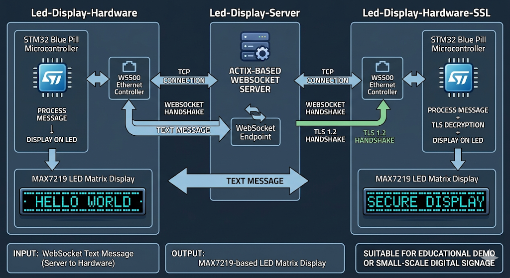
이 저장소는 크게 세 부분으로 구성됩니다. led-display-hardware는 STM32 Blue Pill, W5500, MAX7219 LED 매트릭스를 사용하는 임베디드 펌웨어이며, led-display-server는 Actix 기반의 WebSocket 서버입니다. 여기에 더해 led-display-hardware-ssl은 동일한 하드웨어 구조 위에 TLS 1.2를 추가한 확장 버전입니다.
전체 동작 흐름은 비교적 단순하고 명확합니다. 서버는 WebSocket 엔드포인트를 열고, 임베디드 장치는 W5500을 통해 TCP 연결을 생성한 뒤 WebSocket 핸드셰이크를 수행합니다. 이후 서버에서 전달된 텍스트 메시지를 수신해 LED 패널에 스크롤 형태로 출력합니다. 다시 말해, 입력은 WebSocket 텍스트 메시지이고 출력은 MAX7219 기반 LED 매트릭스 화면입니다.
이미지 출처 : AI 생성
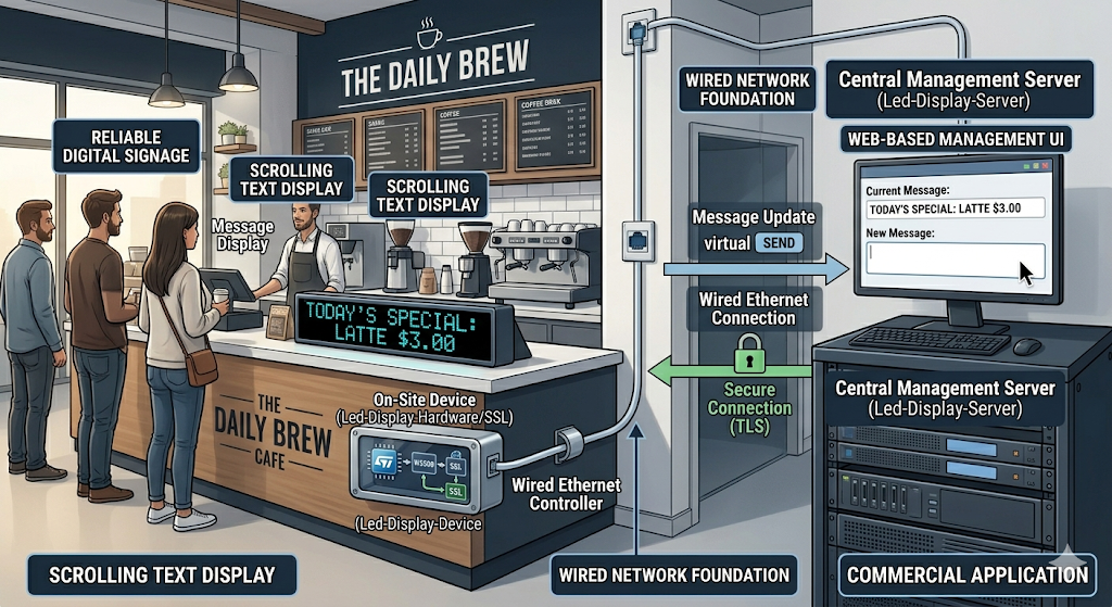
이 구조는 교육용 데모로도 적합하지만, 상업용 관점에서 보면 유선 네트워크 기반 소형 디지털 사이니지의 축소판으로 이해하셔도 무방합니다. 서버에서 문구를 보내고, 현장 장치가 이를 받아 안정적으로 표시하는 구조이기 때문입니다.
이미지 출처 : AI 생성
WIZnet이 들어가는 위치
이 프로젝트에서 사용된 WIZnet 제품은 W5500입니다. W5500은 단순한 이더넷 인터페이스가 아니라, 실제 TCP 연결을 열고 데이터를 송수신하는 네트워크 엔진 역할을 수행합니다. 펌웨어는 SPI를 통해 W5500을 초기화하고, MAC 주소와 IP 주소를 설정한 뒤 TCP 소켓을 열어 서버와 연결합니다. 그리고 그 위에 WebSocket 프레이밍 로직이 올라가면서 최종적으로 LED 표시 애플리케이션이 동작합니다.
이 구조가 실용적인 이유는 작은 MCU가 이더넷 스택 전체를 직접 감당하지 않아도 되기 때문입니다. STM32F103 같은 리소스가 제한된 MCU에서는 문자열 처리, 화면 갱신, 예외 대응만으로도 여유가 크지 않을 수 있습니다. 이때 W5500이 네트워크 계층의 많은 부분을 맡아 주면, 전체 시스템은 더 단순해지고 디버깅도 쉬워집니다.
상업용 환경에서도 이러한 방식은 의미가 있습니다. 무선 환경은 설치 위치, AP 상태, RF 간섭 같은 변수의 영향을 받기 쉽지만, 이 프로젝트처럼 유선 Ethernet 기반으로 설계하면 네트워크 경로를 예측하기 쉽고 장기 운용 시 안정성도 확보하기 수월합니다. 공장, 전시장, 안내 패널, 로비 디스플레이처럼 한 번 설치한 뒤 오래 동작해야 하는 장치에 잘 맞는 접근입니다.
구현 포인트
이 프로젝트에서 W5500 사용 여부는 코드 구조에서도 명확하게 확인됩니다. 먼저 하드웨어 펌웨어는 하나의 SPI 버스를 공유하면서도 W5500과 MAX7219를 서로 다른 CS 핀으로 분리해 제어합니다.
let mut w5500 = W5500::new(cs_ethernet);
let mut max7219 = MAX7219::new(&mut cs_max7219, 20);
이 부분은 하나의 SPI 버스를 공유하면서도 Ethernet 컨트롤러와 LED 드라이버를 각각 독립적으로 제어할 수 있도록 설계했다는 점에서 중요합니다. 배선과 자원 사용을 단순하게 유지하면서도, 두 장치를 동시에 안정적으로 운영할 수 있는 구조이기 때문입니다.
네트워크 초기화 부분에서도 W5500이 실제 TCP 엔드포인트로 사용된다는 점이 분명하게 드러납니다.
w5500.set_ip(spi, &IpAddress::new(192, 168, 1, 33))?;
w5500.open_tcp(spi, self.connection.socket)?;
w5500.connect(spi, Socket::Socket0, host_ip, host_port)?;
이 코드는 정적 IP를 설정하고, TCP 소켓을 열고, 원격 서버에 접속하는 흐름을 보여줍니다. 즉, 애플리케이션은 저수준 이더넷 처리보다 “서버에 연결해 문자열을 받아 화면에 표시하는 일”에 더 집중할 수 있습니다.
WebSocket 처리도 자연스럽게 이어집니다. 펌웨어는 WebSocket 경로를 지정해 핸드셰이크를 수행한 뒤, 수신한 텍스트 메시지를 LED 패널의 스크롤 함수로 전달합니다. 서버 쪽은 특정 룸 기반 경로를 열고, 수신된 메시지를 연결된 클라이언트에 전달합니다. 결과적으로 서버에서 보낸 문자열이 임베디드 디스플레이에 바로 반영되는 구조가 완성됩니다.
또한 저장소에는 TLS 확장 버전도 포함되어 있습니다. 이 버전은 W5500 기반 TCP 연결 위에 BearSSL을 올리고, NTP를 통해 시간을 동기화해 인증서 검증에 필요한 기반을 마련합니다. 다만 이 구조는 보안 확장 방향을 보여주는 데 의미가 있으며, 실제 상업 제품에 적용하려면 엔트로피 처리와 인증서 검증 체계를 더 보강하셔야 합니다.
실무 적용 시 주의할 점
이 프로젝트를 실제 장치 설계 관점에서 보실 때 가장 먼저 확인하셔야 할 부분은 SPI 버스 공유 방식입니다. W5500과 MAX7219가 같은 SPI 라인을 사용할 경우, CS 핀 제어가 명확하지 않으면 화면 이상과 통신 오류가 함께 발생할 수 있습니다. 따라서 회로 설계뿐 아니라 펌웨어 타이밍까지 함께 점검하셔야 합니다.
또한 예제는 정적 IP 기반으로 동작하기 때문에, 실제 상업용 환경에서는 DHCP 예약, 네트워크 설정 저장, 현장 변경 기능 같은 운영 요소를 추가로 고려하시는 것이 좋습니다. 설치 이후 유지보수를 생각하면 이 부분의 차이가 상당히 크게 작용합니다.
버퍼 크기와 메시지 길이도 함께 보셔야 합니다. 짧은 영문 문자열 위주라면 큰 문제가 없겠지만, 긴 문장이나 UTF-8 기반 다국어 문자열을 처리하려면 잘림, 지연, 표시 깨짐 문제가 생길 수 있습니다. 상업용 표시 장치라면 표시 정책과 메시지 길이 제한을 명확히 두는 편이 좋습니다.
마지막으로 네트워크 복구 전략도 중요합니다. 서버 heartbeat, 장치 reconnect, watchdog, 예외 처리 정책이 제대로 설계되지 않으면 현장에서는 일시적인 네트워크 장애만으로도 장치가 멈춘 것처럼 보일 수 있습니다. 데모 단계에서는 보이지 않던 문제가 실제 설치 환경에서는 자주 드러나므로, 이 부분은 반드시 별도 설계 항목으로 보셔야 합니다.
FAQ
Q1. 왜 이 프로젝트에 W5500이 적합한가요?
W5500은 하드웨어 기반 TCP/IP 오프로딩 구조를 제공하기 때문에, MCU가 네트워크 스택 전체를 직접 처리하지 않아도 됩니다. 이 프로젝트처럼 문자열을 받아 LED에 표시하는 장치에서는 애플리케이션 로직을 단순하게 유지하는 것이 중요하므로, W5500의 역할이 매우 실용적입니다.
Q2. W5500은 STM32와 어떻게 연결되나요?
이 예제에서는 SPI1 버스를 사용하며, W5500과 MAX7219가 같은 SPI 라인을 공유합니다. 대신 각 장치는 별도의 CS 핀으로 구분됩니다. 이런 방식은 배선을 단순하게 유지하면서도 여러 SPI 장치를 효율적으로 구성하는 데 적합합니다.
Q3. 이 프로젝트에서 W5500은 실제로 어떤 역할을 하나요?
W5500은 IP 설정, TCP 소켓 오픈, 서버 연결, 데이터 송수신을 담당합니다. 그 위에서 WebSocket 로직이 동작하므로, 전체 시스템에서 W5500은 문자열 표시 장치가 서버와 통신할 수 있게 만드는 핵심 네트워크 계층이라고 보시면 됩니다.
Q4. 초보자도 따라 할 수 있을까요?
완전 초보자에게는 다소 어려울 수 있습니다. 임베디드 Rust, SPI 배선, STM32 플래싱, 네트워크 개념을 어느 정도 알고 계셔야 전체 구조를 편하게 따라가실 수 있습니다. 다만 목표가 분명한 프로젝트이기 때문에, 중급 수준의 임베디드 개발자에게는 좋은 학습 예제가 될 수 있습니다.
Q5. 상업용으로 확장할 때 가장 먼저 보강해야 할 부분은 무엇인가요?
가장 먼저 보셔야 할 부분은 네트워크 설정 관리, 재접속 안정성, watchdog, 문자열 길이 처리, 그리고 TLS 적용 시 보안 강도입니다. 데모는 구조 이해에는 매우 좋지만, 제품화 단계에서는 장애 복구와 운영 편의성까지 함께 설계하셔야 합니다.
Project Overview
This repository is made up of three main parts. led-display-hardware is the embedded firmware that uses an STM32 Blue Pill, a W5500, and a MAX7219 LED matrix. led-display-server is an Actix-based WebSocket server. In addition, led-display-hardware-ssl is an extended version that adds TLS 1.2 on top of the same hardware structure.
The overall operation flow is relatively simple and clear. The server opens a WebSocket endpoint, and the embedded device creates a TCP connection through the W5500 before performing the WebSocket handshake. It then receives text messages sent by the server and displays them as scrolling text on the LED panel. In other words, the input is a WebSocket text message, and the output is a MAX7219-based LED matrix display.
Image source: AI-generated
This structure works well as an educational demo, but from a commercial perspective, it can also be understood as a compact version of a wired network-based digital signage system. The server sends text, and the deployed device receives it and displays it reliably.
Image source: AI-generated
Where WIZnet Fits
The WIZnet product used in this project is the W5500. The W5500 is not just a simple Ethernet interface. It acts as a network engine that actually opens TCP connections and handles data transmission and reception. The firmware initializes the W5500 over SPI, sets the MAC address and IP address, opens a TCP socket, and connects to the server. On top of that, WebSocket framing logic is added, and the final LED display application runs on that foundation.
This structure is practical because a small MCU does not need to handle the entire Ethernet stack directly. On a resource-constrained MCU such as the STM32F103, even string processing, display updates, and exception handling can already consume a meaningful share of the available resources. When the W5500 takes care of much of the network layer, the whole system becomes simpler and easier to debug.
This approach is also meaningful in commercial environments. Wireless systems are easily affected by variables such as installation location, AP condition, and RF interference. By contrast, a wired Ethernet-based design like this makes the network path easier to predict and generally easier to keep stable over long-term operation. It is a good fit for devices that need to be installed once and run for a long time, such as factory displays, exhibition signage, information panels, and lobby displays.
Implementation Points
The use of the W5500 in this project is clearly visible in the code structure as well. First, the hardware firmware shares a single SPI bus while controlling the W5500 and MAX7219 separately through different CS pins.
let mut w5500 = W5500::new(cs_ethernet);
let mut max7219 = MAX7219::new(&mut cs_max7219, 20);
This part is important because it shows that the system is designed to independently control the Ethernet controller and the LED driver while still sharing one SPI bus. It keeps the wiring and resource usage simple while allowing both devices to operate reliably at the same time.
The network initialization section also clearly shows that the W5500 is being used as a real TCP endpoint.
w5500.set_ip(spi, &IpAddress::new(192, 168, 1, 33))?;
w5500.open_tcp(spi, self.connection.socket)?;
w5500.connect(spi, Socket::Socket0, host_ip, host_port)?;
This code shows the flow of setting a static IP, opening a TCP socket, and connecting to a remote server. In other words, the application can focus less on low-level Ethernet processing and more on receiving strings from the server and displaying them on the screen.
The WebSocket processing also follows naturally from there. The firmware specifies the WebSocket path, performs the handshake, and then passes the received text messages to the LED panel’s scrolling function. On the server side, a room-based path is opened, and received messages are forwarded to connected clients. As a result, strings sent by the server are immediately reflected on the embedded display.
The repository also includes a TLS extension version. This version layers BearSSL on top of the W5500-based TCP connection and synchronizes time through NTP to provide the basis for certificate validation. However, this structure is mainly meaningful as an example of the security extension direction. To apply it to an actual commercial product, the entropy handling and certificate validation chain would need to be strengthened further.
Practical Considerations for Real-World Use
When looking at this project from the perspective of a real device design, the first thing to check is the shared SPI bus arrangement. If the W5500 and MAX7219 use the same SPI lines, unclear CS control can lead to both display issues and communication errors at the same time. For that reason, not only the circuit design but also the firmware timing should be reviewed carefully.
The example also operates with a static IP configuration, so in a real commercial environment it would be better to consider operational features such as DHCP reservation, saved network settings, and on-site configuration changes. Once the system is deployed, these details can make a significant difference in maintenance.
You should also review buffer size and message length together. If the system only handles short English strings, there may be little problem. However, longer sentences or UTF-8 based multilingual strings can cause truncation, delay, or broken display output. For a commercial display device, it is better to define a clear display policy and message length limit.
Finally, the network recovery strategy is also important. If server heartbeat handling, device reconnection, watchdog behavior, and exception handling are not designed properly, even a temporary network issue can make the device appear to be frozen in the field. Problems that are not obvious at the demo stage often appear frequently in real installation environments, so this part should be treated as a separate design consideration.
FAQ
Q1. Why is the W5500 a good fit for this project?
The W5500 provides hardware-based TCP/IP offloading, so the MCU does not need to process the entire network stack by itself. In a device like this, which receives strings and displays them on an LED matrix, keeping the application logic simple is important, and that makes the W5500 a very practical choice.
Q2. How is the W5500 connected to the STM32?
In this example, SPI1 is used, and the W5500 and MAX7219 share the same SPI lines. However, each device is separated by its own CS pin. This approach is suitable for keeping the wiring simple while efficiently connecting multiple SPI devices.
Q3. What exactly does the W5500 do in this project?
The W5500 handles IP configuration, TCP socket opening, server connection, and data transmission and reception. Since the WebSocket logic runs on top of that, the W5500 serves as the core network layer that allows the text display device to communicate with the server.
Q4. Can beginners follow this project?
It may be somewhat difficult for complete beginners. You should be reasonably comfortable with embedded Rust, SPI wiring, STM32 flashing, and basic networking concepts to follow the overall structure without difficulty. That said, because the project goal is very clear, it can still be a good learning example for intermediate embedded developers.
Q5. What should be improved first when expanding this into a commercial product?
The first areas to strengthen are network configuration management, reconnection reliability, watchdog behavior, string length handling, and the security strength of the TLS implementation. The demo is very good for understanding the structure, but at the product stage, you also need to design for fault recovery and operational convenience.
-
Github Code
