


IND.I/O switching application with Modbus TCP
controling a set of disinfection lights based on sensor readings

WIZnet - W5500
x 1

프로젝트 개요와 동작
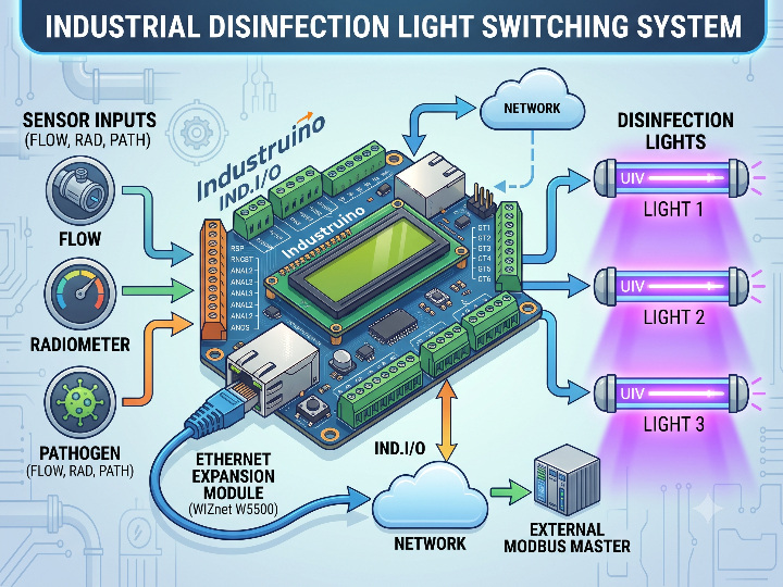
이 프로젝트는 Industruino IND.I/O를 이용해 센서 상태에 따라 세 개의 소독 조명을 자동으로 제어하는 산업용 스위칭 시스템입니다.
IND.I/O는 유속 센서와 방사계에서 전달되는 4–20mA 신호, 병원체 감지기의 0–5V 신호를 읽습니다. 측정된 값에 따라 필요한 조명 수를 결정하고, 세 개의 디지털 출력으로 릴레이를 제어합니다.
WIZnet W5500이 탑재된 Ethernet Expansion Module은 IND.I/O를 Modbus TCP 네트워크에 연결합니다. 외부 Modbus Master는 Ethernet을 통해 센서값, 조명 동작 단계, 누적 운전 시간과 시스템 상태를 확인할 수 있습니다.
전체 동작은 다음 순서로 진행됩니다.
- IND.I/O가 유속 센서와 방사계의 4–20mA 신호를 측정합니다.
- 병원체 감지기의 0–5V 신호를 함께 확인합니다.
- 측정값을 기준으로 필요한 조명 수를 1단계부터 3단계까지 계산합니다.
- 사용 시간이 가장 짧은 조명을 우선 선택합니다.
- 디지털 출력으로 릴레이를 구동합니다.
- 현재 상태를 LCD와 Modbus TCP 입력 레지스터에 기록합니다.
- 외부 Modbus Master가 해당 레지스터를 주기적으로 읽습니다.
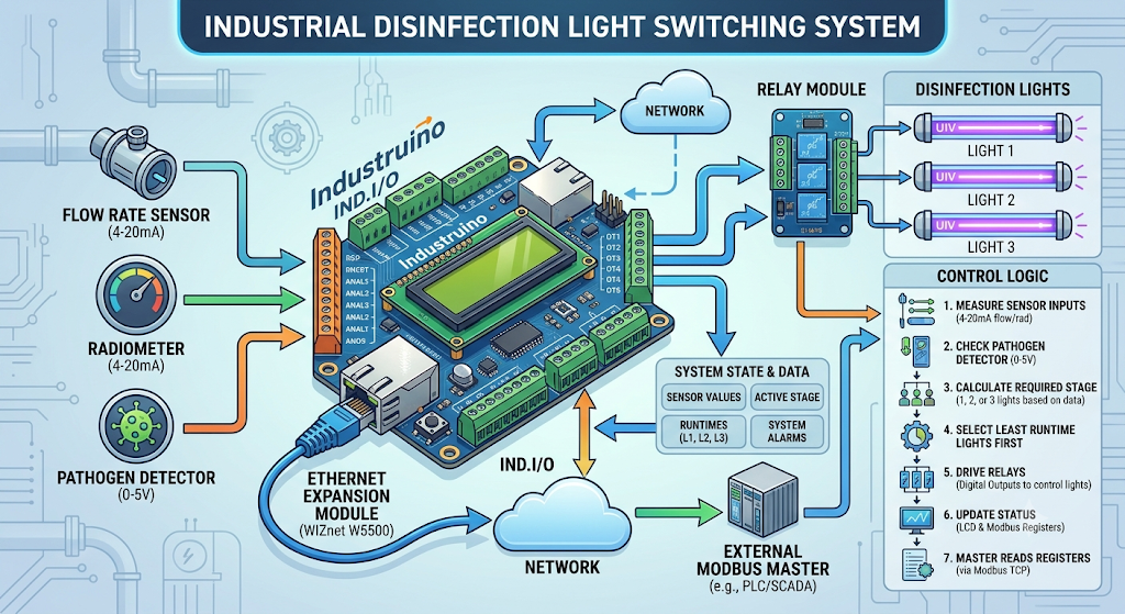
병원체 감지 신호는 일반적인 유속 기반 제어보다 우선하는 조건으로 사용됩니다. 특정 위험 상태가 감지되면 유속 계산 결과와 관계없이 추가 조명을 작동시키는 구조입니다.
또한 조명을 항상 같은 순서로 켜지 않습니다. 각 조명 세트의 누적 운전 시간을 기록하고, 사용 시간이 가장 짧은 조명을 먼저 선택합니다. 일정 시간이 지나면 가동 대상을 교체해 특정 조명과 릴레이에 운전 시간이 집중되는 것을 줄입니다.
센서값과 제어 단계는 IND.I/O의 LCD에서 확인할 수 있습니다. 동일한 정보는 Modbus TCP 입력 레지스터에도 저장됩니다.
외부 Master에서 확인할 수 있는 주요 정보는 다음과 같습니다.
- 유속 센서 측정값
- 방사계 측정값
- 병원체 감지 상태
- 현재 조명 제어 단계
- 각 조명의 누적 운전 시간
- 시스템 운전 상태
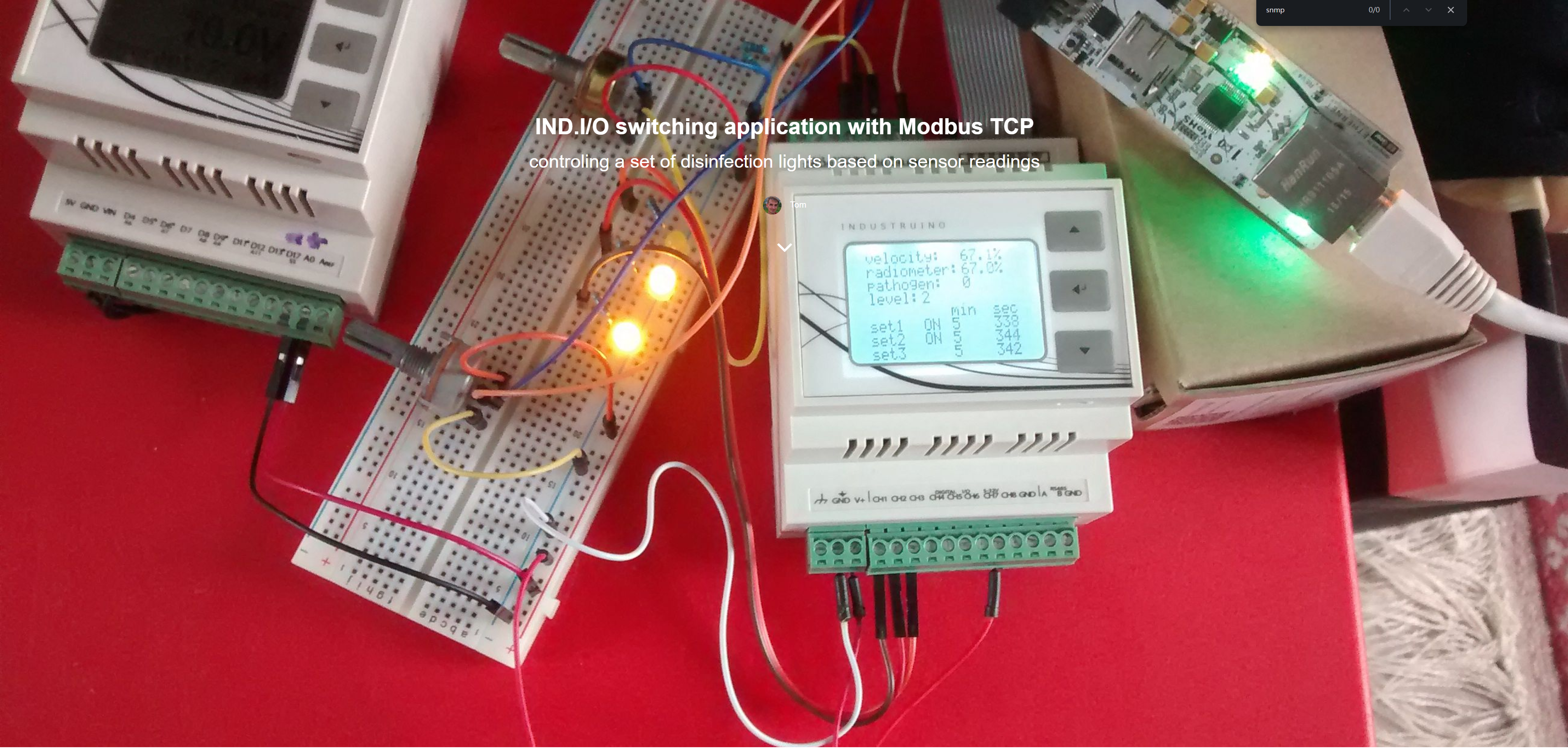
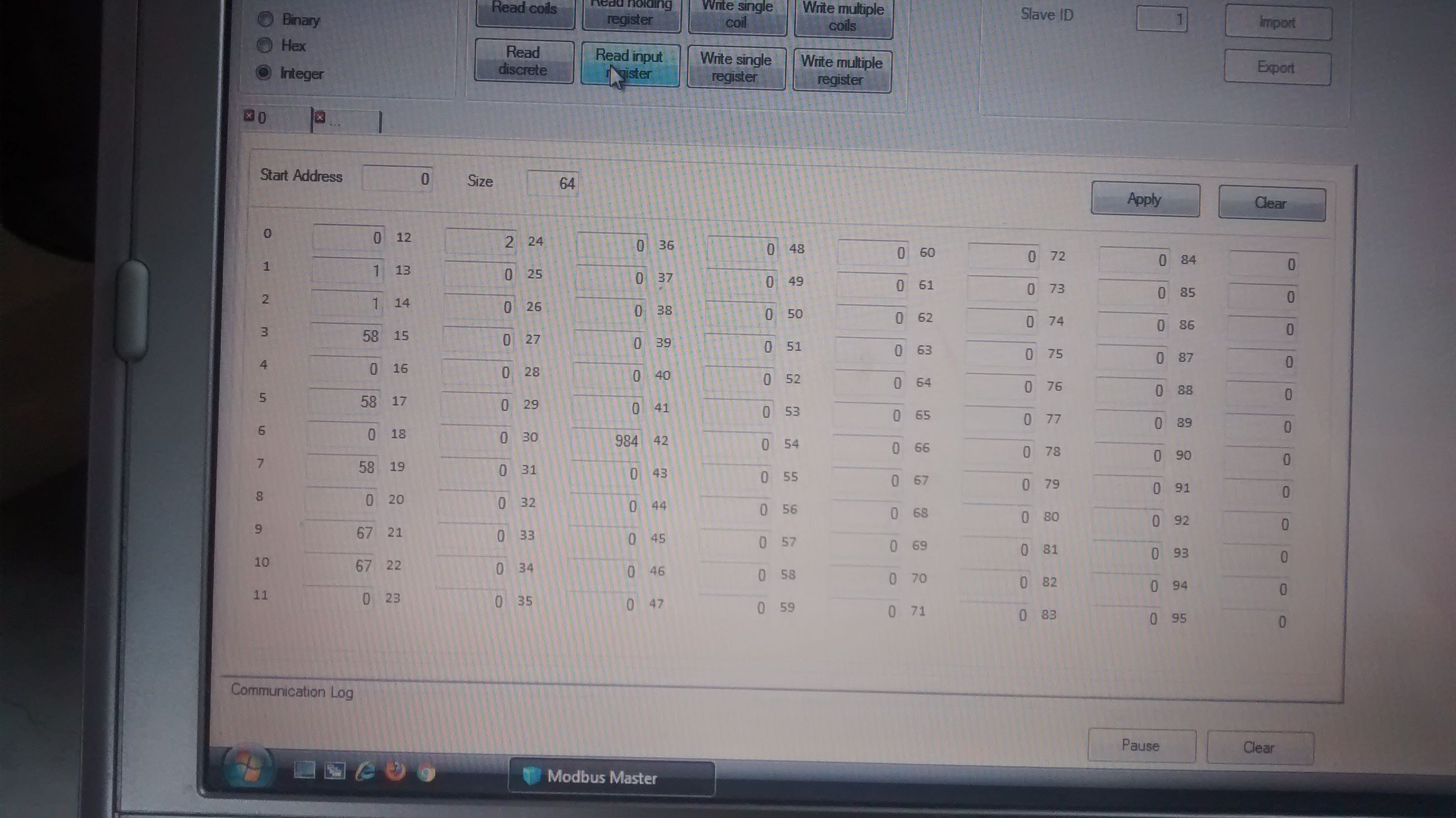
이미지 출처 : IND.I/O switching application with Modbus TCP | Industruino
H/W 구성
이 프로젝트는 IND.I/O 제어기, W5500 기반 Ethernet Expansion Module, 산업용 센서와 릴레이 출력으로 구성됩니다.
4–20mA 유속 센서 ─────┐
4–20mA 방사계 ────────┼──> Industruino IND.I/O ──> 릴레이 3채널 ──> 소독 조명
0–5V 병원체 감지기 ───┘              │
                                      │ 14핀 IDC / SPI
                                      ▼
                         Ethernet Expansion Module
                              WIZnet W5500
                                      │
                                   RJ45
                                      │
                                      ▼
                            Modbus TCP Master
Industruino IND.I/O
IND.I/O는 센서 입력을 측정하고 릴레이 출력을 제어하는 메인 컨트롤러입니다.
구형 IND.I/O 제품군은 다음과 같은 산업용 인터페이스를 제공합니다.
- 4채널 0–10V 또는 4–20mA 아날로그 입력
- 2채널 0–10V 또는 4–20mA 아날로그 출력
- 8채널 24V 디지털 입출력
- 절연 RS485 인터페이스
- MCU, 아날로그 및 디지털 영역의 분리 전원
- LCD와 전면 버튼
- 14핀 IDC 확장 포트
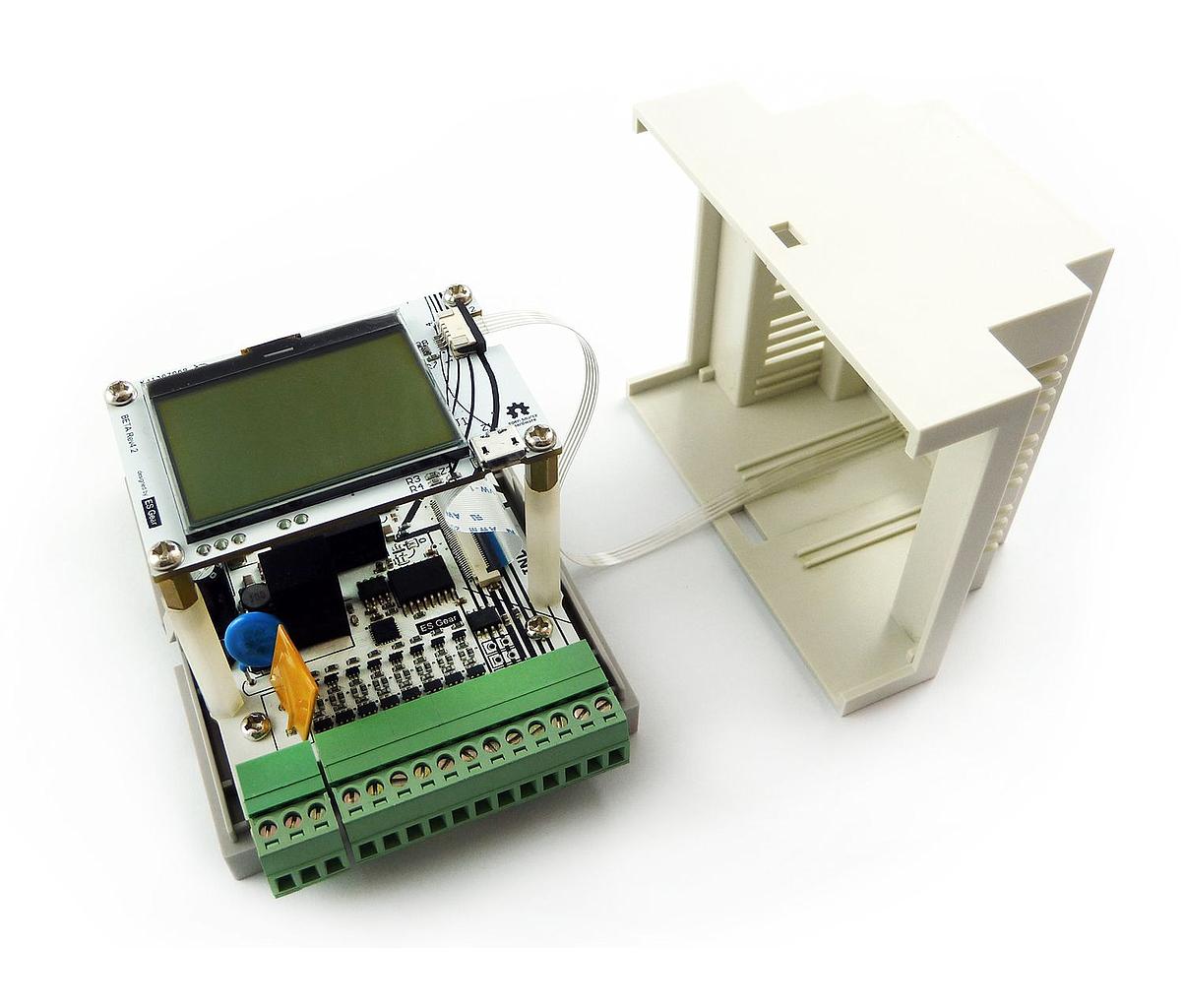
이미지 출처 : Industruino IND.I/O kit | Industruino
Industruino Ethernet Expansion Module
Ethernet Expansion Module은 14핀 IDC 포트를 통해 IND.I/O에 연결되는 DIN 레일형 네트워크 모듈입니다.
주요 구성은 다음과 같습니다.
- WIZnet W5500 Ethernet Controller
- 10Base-T 및 100Base-TX RJ45 인터페이스
- MicroSD 카드 슬롯
- 8KB 비휘발성 FRAM
- 5V 동작
- 14핀 IDC 확장 포트
MicroSD는 로그나 비교적 큰 데이터를 저장하는 데 사용할 수 있습니다. FRAM은 설정값, 운전 시간과 같이 크기는 작지만 자주 변경되는 데이터를 기록하는 용도에 적합합니다.
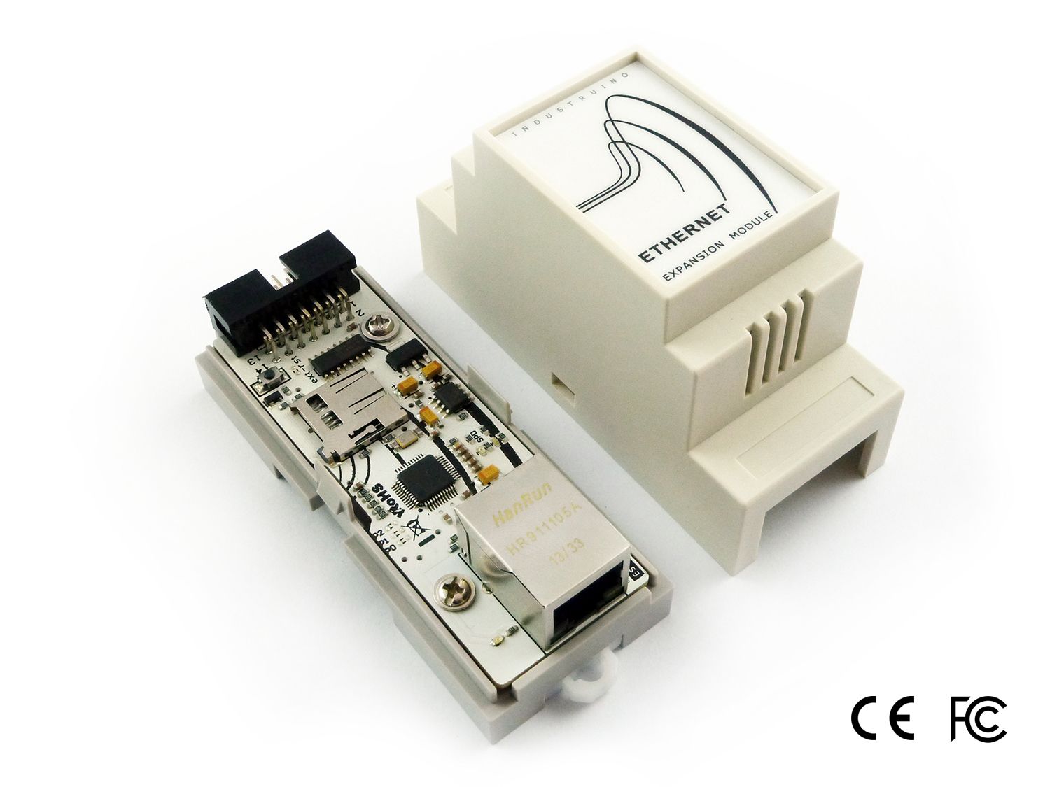
이미지 출처 : Ethernet expansion module | Industruino
센서와 출력 장치
원문에서 확인되는 필드 장치는 다음과 같습니다.
- 4–20mA 유속 센서
- 4–20mA 방사계
- 0–5V 병원체 감지 신호
- 소독 조명용 릴레이 3채널
- 소독 조명 3세트
원문 시연에서는 유속 센서와 방사계 입력을 가변저항으로 대체했습니다. 릴레이 출력 상태는 실제 소독 조명 대신 LED로 표시했습니다.
센서, 릴레이와 조명의 제조사 및 모델명은 공개되지 않았습니다.
WIZnet W5500의 역할
W5500은 센서값을 측정하거나 릴레이를 직접 제어하지 않습니다. IND.I/O와 Modbus TCP Master 사이의 Ethernet 통신을 담당합니다.
주요 기능은 다음과 같습니다.
- TCP 연결 관리
- 소켓 상태 유지
- Ethernet 패킷 송수신
- 송수신 버퍼 관리
- Modbus TCP 데이터 전송
- 10/100Mbps Ethernet PHY 제공
IND.I/O의 MCU는 센서 측정, 조명 단계 계산, 운전 시간 관리, LCD 표시와 Watchdog 처리에 집중합니다. W5500은 네트워크 처리를 별도로 수행해 제어 기능과 통신 기능을 분리합니다.
W5500에는 하드웨어 TCP/IP 스택, 8개의 독립적인 소켓과 32KB 송수신 버퍼가 포함되어 있습니다. MCU와는 SPI로 연결됩니다.
이 구조에서는 MCU가 전체 소프트웨어 TCP/IP 스택을 직접 처리하지 않아도 됩니다. 따라서 애플리케이션 코드에서 네트워크 구현 범위를 줄이고 센서와 출력 제어에 더 많은 자원을 사용할 수 있습니다.
다만 공개된 프로젝트 자료에는 CPU 사용률, Modbus 응답 시간 또는 장시간 패킷 손실률에 대한 시험 결과가 없습니다. 따라서 이 프로젝트의 장점은 정량적인 성능 수치보다 제어 로직과 네트워크 처리 기능을 분리한 구조에서 확인할 수 있습니다.
산업 환경에서의 안정성
이 시스템의 안정성은 W5500 하나만으로 확보되는 것이 아닙니다. IND.I/O의 전원 구조, 입출력 보호 회로, 유선 Ethernet과 Watchdog이 함께 작동합니다.
IND.I/O의 아날로그 입력에는 ESD와 과도 신호 보호 기능이 적용되어 있습니다. 디지털 출력은 단락, 과전류, 과열, ESD와 과도전압에 대응하도록 설계되어 있습니다.
MCU 영역과 필드 입출력 영역도 분리되어 있습니다. 이러한 구조는 센서 배선이나 출력 부하에서 발생한 전기적 노이즈가 제어 회로에 직접 영향을 주는 위험을 줄여줍니다.
유선 Ethernet은 무선 신호 세기, 채널 혼잡과 액세스 포인트 상태의 영향을 받지 않습니다. 고정된 제어반과 상위 시스템 사이에서 일정한 주기로 Modbus 데이터를 읽는 환경에서는 연결 상태와 장애 원인을 비교적 명확하게 관리할 수 있습니다.
Watchdog은 펌웨어가 정지했을 때 MCU를 재시작하는 복구 수단입니다. 그러나 안전회로나 비상 정지 장치를 대신하지는 않습니다.
재시작 직후 릴레이 출력이 어떤 상태가 되는지 정의해야 합니다. 위험 부하는 외부 인터록과 독립적인 차단 회로로 보호해야 합니다.
성능을 결정하는 요소
전체 시스템의 응답 속도는 Ethernet 전송 속도만으로 결정되지 않습니다. 이 프로젝트에서는 아날로그 입력의 변환 속도가 실제 제어 주기에 더 큰 영향을 줄 수 있습니다.
IND.I/O의 ADC 변환 속도는 설정한 분해능에 따라 달라집니다.
18비트: 초당 3.75회
16비트: 초당 15회
14비트: 초당 60회
12비트: 초당 240회
높은 분해능을 선택하면 더 세밀한 측정값을 얻을 수 있지만 새로운 데이터가 생성되는 속도는 느려집니다. 반대로 낮은 분해능은 빠른 갱신에 유리하지만 측정 정밀도는 낮아집니다.
Modbus Master의 Polling 주기를 ADC 변환 주기보다 지나치게 빠르게 설정하면 동일한 측정값을 반복해서 읽을 가능성이 높습니다.
Polling 주기는 다음 조건을 기준으로 설정하는 것이 적절합니다.
센서 자체의 응답 속도
입력 신호의 노이즈 수준
조명 제어에 필요한 반응 시간
필요한 측정 분해능
네트워크에 연결된 Modbus 장치 수
소독 조명처럼 물리적 변화가 비교적 느린 장치를 제어한다면 매우 짧은 통신 주기보다 안정적인 센서 측정과 적절한 필터링이 더 중요할 수 있습니다.
구현 노트
공개된 자료에는 전체 애플리케이션 스케치가 포함되어 있지 않습니다. 원문에서는 MgsModbus의 Slave 예제를 기반으로 구현했다고 설명하며, 네트워크 주소와 라이브러리 설정에 필요한 변경 사항만 제시합니다.
따라서 아래 코드는 전체 프로젝트 코드가 아니라 Industruino Ethernet Module 문서에서 확인할 수 있는 W5500 설정 일부입니다.
Ethernet2 라이브러리 구성
Industruino Ethernet Module 예제에서는 SPI와 Ethernet2 라이브러리를 사용합니다.
#include <SPI.h>
#include <Ethernet2.h>
문서에서는 Ethernet2 라이브러리 내부의 w5500.cpp 파일에서 W5500의 SPI 주파수를 4MHz로 설정하도록 안내합니다.
이 값은 W5500의 최대 SPI 속도가 아니라 Industruino 모듈에서 제시하는 기준 설정입니다. 먼저 4MHz에서 장시간 통신 안정성을 확인한 뒤, 필요한 경우에만 속도 변경을 검토하는 것이 안전합니다.
공유 SPI 장치 선택
Ethernet Expansion Module의 W5500, MicroSD와 FRAM은 하나의 SPI 버스를 공유합니다. 각 장치는 별도의 Chip Select 신호로 구분합니다.
void setup() {
    pinMode(4, OUTPUT);   // MicroSD CS
    pinMode(6, OUTPUT);   // FRAM CS
    pinMode(10, OUTPUT);  // W5500 CS

    digitalWrite(4, HIGH);
    digitalWrite(6, HIGH);
    digitalWrite(10, HIGH);
}

// W5500 선택
digitalWrite(4, HIGH);
digitalWrite(6, HIGH);
digitalWrite(10, LOW);
Chip Select는 Active-Low 방식입니다. W5500을 선택할 때 MicroSD와 FRAM의 CS를 HIGH로 유지하지 않으면 두 개 이상의 장치가 동시에 SPI 버스를 구동할 수 있습니다.
기본 연결은 다음과 같습니다.
W5500 CS: D10
W5500 외부 Reset: D5
W5500 IRQ: D7
MicroSD CS: D4
FRAM CS: D6
SPI MISO: D14
SPI SCLK: D15
SPI MOSI: D16
Modbus TCP 설정
원문 예제에서는 다음 네트워크 값을 사용합니다.
Slave IP: 192.168.1.99
Gateway: 192.168.1.1
Subnet Mask: 255.255.255.0
Modbus TCP Port: 502
Slave 스케치에 설정된 IP 주소와 MgsModbus.cpp의 ServerIp는 같아야 합니다. 두 값이 다르면 Master가 Slave에 정상적으로 연결되지 않습니다.
고정 IP는 DHCP 자동 할당 범위와 겹치지 않도록 관리해야 합니다. 현장에서는 MAC 주소, IP 주소와 Modbus 레지스터 맵을 제어반 문서에 함께 기록하는 것이 좋습니다.
Modbus 레지스터 설계
Master와 Slave는 각 레지스터의 주소와 데이터 형식을 동일하게 정의해야 합니다.
레지스터 맵에는 다음 정보를 포함하는 것이 좋습니다.
레지스터 시작 주소
측정값의 단위
정수 또는 부호 있는 값의 구분
소수점 위치
32비트 데이터의 워드 순서
오류 또는 미측정 상태를 나타내는 값
통신 연결이 정상이어도 데이터 형식이 일치하지 않으면 Master에서 잘못된 센서값이나 운전 시간으로 해석할 수 있습니다.
실무 적용 시 주의사항
전원을 끈 상태에서 14핀 IDC 모듈을 연결하거나 분리해야 합니다.
부팅 직후 W5500, MicroSD와 FRAM의 Chip Select를 초기화해야 합니다.
공식 기준인 4MHz SPI 설정으로 장시간 통신을 먼저 검증해야 합니다.
고정 IP는 DHCP 주소 범위와 분리해 관리해야 합니다.
32비트 레지스터의 워드 순서를 Master와 Slave에서 통일해야 합니다.
Watchdog 재시작 전후의 릴레이 출력 상태를 정의해야 합니다.
안전 관련 부하는 외부 인터록과 독립 차단 회로를 사용해야 합니다.
유사 프로젝트: PLC_PRS10
https://maker.wiznet.io/lawrence/projects/plc%2Dprs10/
PLC_PRS10은 Arduino와 WIZnet W5100 또는 W5500을 이용해 구성한 소형 PLC형 Modbus TCP 컨트롤러입니다.
Arduino ATmega328P가 두 개의 릴레이, 네 개의 디지털 입력과 DS18B20 온도 센서를 처리합니다. WIZnet Ethernet Controller는 TCP 502번 포트에서 Modbus TCP Slave를 실행하며, SCADA가 릴레이와 입력 상태를 읽거나 제어할 수 있도록 합니다.
PLC_PRS10에는 Ethernet 케이블이 분리되었다가 다시 연결될 때 네트워크와 Modbus Server를 재초기화하는 Ethernet Watchdog도 포함되어 있습니다.
유사점
| 항목 | 공통 내용 |
|---|---|
| 네트워크 방식 | 두 프로젝트 모두 WIZnet Ethernet Controller를 이용한 유선 Ethernet을 사용합니다. |
| 산업 프로토콜 | Modbus TCP Slave로 동작하며 TCP 502번 포트를 사용합니다. |
| MCU 연결 | WIZnet Controller와 MCU가 SPI로 연결됩니다. |
| 현장 입출력 | 센서 또는 접점 입력을 읽고 릴레이 출력을 제어합니다. |
| 상위 시스템 | 외부 Modbus Master 또는 SCADA에서 상태를 확인할 수 있습니다. |
| 주소 설정 | 고정 IP를 기준으로 네트워크에 연결합니다. |
| 복구 기능 | 무인 운전을 고려한 Watchdog 또는 통신 복구 기능을 포함합니다. |
두 프로젝트 모두 소형 MCU가 현장 입출력을 처리하고, WIZnet Controller가 Modbus TCP 통신을 담당하는 동일한 기본 구조를 사용합니다.
차이점
| 항목 | Industruino 프로젝트 | PLC_PRS10 |
| 주요 목적 | 공기 흐름과 병원체 상태에 따른 소독 조명 제어 | 범용 SCADA용 소형 PLC 및 Remote I/O |
| 메인 컨트롤러 | ATmega 기반 Industruino IND.I/O | ATmega328P 기반 Arduino |
| Ethernet 장치 | W5500이 탑재된 전용 Expansion Module | W5100 또는 W5500을 선택해 사용 |
| 입력 구성 | 4–20mA 센서 2개와 0–5V 감지 신호 | 디지털 입력 4개와 DS18B20 온도 센서 |
| 출력 구성 | 소독 조명용 릴레이 3개 | 범용 릴레이 2개 |
| 제어 로직 | 센서값에 따라 조명 수를 계산하고 누적 운전 시간을 균등화 | SCADA의 Coil 명령에 따라 릴레이를 직접 제어 |
| Modbus 데이터 | 센서값과 운전 시간을 주로 Input Register로 제공합니다. | Coil, Discrete Input, Input Register를 분리해 사용합니다. |
| Watchdog 역할 | MCU가 정지하면 하드웨어 Watchdog으로 재시작합니다. | Ethernet 링크 복구 후 네트워크와 Modbus Server를 재초기화합니다. |
| 출력 보호 | 조명별 누적 운전 시간을 분산합니다. | 릴레이 1에 60초 자동 해제 타이머가 적용됩니다. |
| 적용 형태 | 특정 소독 장치를 위한 목적형 제어 시스템 | 다양한 SCADA 환경에 연결할 수 있는 범용 PLC형 노드 |
FAQ
Q: 이 프로젝트에서 W5500을 사용하는 이유는 무엇인가요?
W5500은 TCP/IP 처리, 소켓 상태와 송수신 버퍼를 하드웨어에서 관리합니다. IND.I/O의 MCU는 센서 측정과 릴레이 제어에 집중할 수 있으며, 전체 TCP/IP 스택을 MCU 소프트웨어로 직접 구현할 필요가 없습니다.
Q: W5500은 어떤 하드웨어에 탑재되어 있나요?
W5500은 Industruino Ethernet Expansion Module에 탑재되어 있습니다. 이 모듈에는 RJ45 포트, MicroSD 슬롯과 8KB FRAM도 포함되어 있으며, IND.I/O와는 14핀 IDC 포트로 연결됩니다.
Q: W5500은 IND.I/O와 어떻게 통신하나요?
SPI를 사용합니다. MISO, MOSI와 SCLK 신호를 공유하고, W5500 전용 Chip Select 신호로 장치를 선택합니다. 외부 Reset과 IRQ 신호도 제공됩니다.
Q: 초보자도 구현할 수 있나요?
기본 Ethernet 예제와 Modbus Slave 예제를 실행하는 단계는 비교적 단순합니다. 실제 설비에 적용하려면 4–20mA 신호, 릴레이 정격, 고정 IP, Modbus 레지스터, SPI 공유 버스와 Watchdog 동작을 이해해야 합니다.
Q: Wi-Fi 기반 Modbus TCP와 비교하면 어떤 차이가 있나요?
유선 Ethernet은 케이블과 네트워크 스위치가 필요하지만 무선 간섭과 신호 세기의 영향을 받지 않습니다. 고정된 제어반과 설비 사이에서 지속적으로 상태를 읽는 환경에는 W5500 기반 Ethernet이 적합합니다. 이동 장비나 배선이 어려운 장소에서는 Wi-Fi가 더 실용적일 수 있습니다.
Project Overview and Operation
This project is an industrial switching system that uses an Industruino IND.I/O to automatically control three disinfection lamps according to sensor conditions.
The IND.I/O reads 4–20 mA signals from an airflow sensor and a radiometer, as well as a 0–5 V signal from a pathogen detector. Based on the measured values, it determines how many lamps are required and controls the relays through three digital outputs.
An Ethernet Expansion Module equipped with the WIZnet W5500 connects the IND.I/O to a Modbus TCP network. An external Modbus Master can monitor sensor values, the current lamp operating stage, accumulated operating time, and overall system status over Ethernet.
The system operates in the following sequence:
- The IND.I/O measures the 4–20 mA signals from the airflow sensor and radiometer.
- It also checks the 0–5 V signal from the pathogen detector.
- It calculates the required number of lamps, from Stage 1 to Stage 3, based on the measured values.
- It gives priority to the lamp with the shortest accumulated operating time.
- It drives the corresponding relay through a digital output.
- It records the current status on the LCD and in the Modbus TCP input registers.
- An external Modbus Master periodically reads those registers.
Image Source : AI Generated
The pathogen detection signal is used as a higher-priority condition than normal airflow-based control. When a specific hazardous condition is detected, additional lamps can be activated regardless of the airflow calculation result.
The lamps are not always switched on in the same order. The system records the accumulated operating time of each lamp set and selects the lamp with the shortest operating time first. After a defined period, the active lamps are rotated to prevent operating time from being concentrated on specific lamps and relays.
Sensor values and the current control stage can be checked on the IND.I/O LCD. The same information is also stored in the Modbus TCP input registers.
The external Master can monitor the following information:
- Airflow sensor measurement
- Radiometer measurement
- Pathogen detection status
- Current lamp control stage
- Accumulated operating time of each lamp
- Overall system operating status
Image source: IND.I/O Switching Application with Modbus TCP | Industruino
H/W Configuration
This project consists of an IND.I/O controller, a W5500-based Ethernet Expansion Module, industrial sensors, and relay outputs.
4–20 mA airflow sensor ──────┐
4–20 mA radiometer ──────────┼──> Industruino IND.I/O ──> 3-channel relay ──> Disinfection lamps
0–5 V pathogen detector ─────┘              │
                                            │ 14-pin IDC / SPI
                                            ▼
                               Ethernet Expansion Module
                                     WIZnet W5500
                                            │
                                          RJ45
                                            │
                                            ▼
                                  Modbus TCP Master
Industruino IND.I/O
The IND.I/O is the main controller that measures sensor inputs and controls relay outputs.
The earlier IND.I/O product line provides the following industrial interfaces:
Four 0–10 V or 4–20 mA analog inputs
Two 0–10 V or 4–20 mA analog outputs
Eight 24 V digital inputs and outputs
Isolated RS485 interface
Separate power domains for the MCU, analog section, and digital section
LCD and front-panel buttons
14-pin IDC expansion port
Image source: Industruino IND.I/O kit | Industruino
Industruino Ethernet Expansion Module
The Ethernet Expansion Module is a DIN-rail network module connected to the IND.I/O through a 14-pin IDC port.
Its main components are:
WIZnet W5500 Ethernet Controller
10Base-T and 100Base-TX RJ45 interface
MicroSD card slot
8 KB nonvolatile FRAM
5 V operation
14-pin IDC expansion port
The MicroSD card can be used to store logs or relatively large amounts of data. The FRAM is suitable for storing small values that change frequently, such as configuration parameters and accumulated operating times.
Image source: Ethernet expansion module | Industruino
Sensors and Output Devices
The following field devices can be identified from the original project:
4–20 mA airflow sensor
4–20 mA radiometer
0–5 V pathogen detection signal
Three relay channels for the disinfection lamps
Three disinfection lamp sets
In the original demonstration, potentiometers were used in place of the airflow sensor and radiometer inputs. LEDs were used instead of the actual disinfection lamps to indicate relay output states.
The manufacturers and model numbers of the sensors, relays, and lamps were not disclosed.
Role of the WIZnet W5500
The W5500 does not measure sensor values or directly control the relays. It handles Ethernet communication between the IND.I/O and the Modbus TCP Master.
Its main functions are:
TCP connection management
Socket state maintenance
Ethernet packet transmission and reception
Transmit and receive buffer management
Modbus TCP data transfer
10/100 Mbps Ethernet PHY support
The IND.I/O MCU focuses on sensor measurement, lamp-stage calculation, operating-time management, LCD updates, and Watchdog handling. The W5500 performs network processing separately, dividing the control and communication functions.
The W5500 includes a hardware TCP/IP stack, eight independent sockets, and 32 KB of transmit and receive buffer memory. It connects to the MCU through SPI.
With this architecture, the MCU does not need to process the entire software TCP/IP stack directly. This reduces the networking implementation required in the application and leaves more MCU resources available for sensor and output control.
However, the publicly available project materials do not include test results for CPU utilization, Modbus response time, or long-term packet loss. The main advantage demonstrated by this project is therefore the architectural separation between control logic and network processing rather than a quantified performance improvement.
Reliability in Industrial Environments
The reliability of this system is not provided by the W5500 alone. The IND.I/O power architecture, input and output protection circuits, wired Ethernet connection, and Watchdog all contribute to overall system reliability.
The IND.I/O analog inputs include ESD and transient-signal protection. The digital outputs are designed to handle short circuits, overcurrent, overheating, ESD, and overvoltage conditions.
The MCU section and the field I/O section also use separate power domains. This architecture reduces the risk that electrical noise from sensor wiring or output loads will directly affect the control circuitry.
Wired Ethernet is not affected by wireless signal strength, channel congestion, or access-point status. In systems that periodically read Modbus data between a fixed control panel and an upstream system, the connection state and possible failure causes can be managed more clearly.
The Watchdog is a recovery mechanism that restarts the MCU if the firmware stops operating. However, it does not replace a safety circuit or emergency-stop system.
The expected relay-output state immediately after a restart must be defined. Hazardous loads should be protected using external interlocks and independent shutdown circuits.
Factors That Determine Performance
The response speed of the complete system is not determined by Ethernet transmission speed alone. In this project, the analog-input conversion rate may have a greater effect on the actual control cycle.
The IND.I/O ADC conversion rate depends on the selected resolution:
18-bit: 3.75 samples per second
16-bit: 15 samples per second
14-bit: 60 samples per second
12-bit: 240 samples per second
A higher resolution provides more detailed measurements but reduces the rate at which new data is generated. A lower resolution supports faster updates but provides lower measurement precision.
If the Modbus Master polling interval is significantly shorter than the ADC conversion cycle, the Master may repeatedly read the same measurement value.
The polling interval should be selected according to the following conditions:
Response speed of the sensor
Noise level of the input signal
Required lamp-control response time
Required measurement resolution
Number of Modbus devices connected to the network
For equipment such as disinfection lamps, where physical conditions change relatively slowly, stable sensor measurements and appropriate filtering may be more important than an extremely short communication interval.
Implementation Notes
The publicly available materials do not include the complete application sketch. The original article explains that the implementation is based on the MgsModbus Slave example and provides only the required changes to the network address and library configuration.
Therefore, the following code is not the complete project source. It is part of the W5500 configuration described in the Industruino Ethernet Expansion Module documentation.
Ethernet2 Library Configuration
The Industruino Ethernet Module example uses the SPI and Ethernet2 libraries.
#include <SPI.h>
#include <Ethernet2.h>
The documentation instructs the user to configure the W5500 SPI frequency to 4 MHz in the w5500.cpp file inside the Ethernet2 library.
This value is not the maximum SPI speed supported by the W5500. It is the reference setting specified for the Industruino module. It is safer to verify long-term communication reliability at 4 MHz before considering a higher SPI frequency.
Selecting Shared SPI Devices
The W5500, MicroSD card, and FRAM on the Ethernet Expansion Module share a single SPI bus. Each device is selected using a separate Chip Select signal.
void setup() {
    pinMode(4, OUTPUT);   // MicroSD CS
    pinMode(6, OUTPUT);   // FRAM CS
    pinMode(10, OUTPUT);  // W5500 CS

    digitalWrite(4, HIGH);
    digitalWrite(6, HIGH);
    digitalWrite(10, HIGH);
}

// Select the W5500
digitalWrite(4, HIGH);
digitalWrite(6, HIGH);
digitalWrite(10, LOW);
The Chip Select signals are active-low. When the W5500 is selected, the MicroSD and FRAM Chip Select signals must remain HIGH. Otherwise, two or more devices may drive the SPI bus at the same time.
The default signal assignments are:
W5500 CS: D10
W5500 external Reset: D5
W5500 IRQ: D7
MicroSD CS: D4
FRAM CS: D6
SPI MISO: D14
SPI SCLK: D15
SPI MOSI: D16
Modbus TCP Configuration
The original project example uses the following network settings:
Slave IP: 192.168.1.99
Gateway: 192.168.1.1
Subnet Mask: 255.255.255.0
Modbus TCP Port: 502
The IP address configured in the Slave sketch must match the ServerIp value in MgsModbus.cpp. If the two values are different, the Master will not be able to connect to the Slave correctly.
A static IP address should be managed so that it does not overlap with the DHCP allocation range. In an industrial installation, it is also recommended to document the MAC address, IP address, and Modbus register map in the control-panel documentation.
Modbus Register Design
The Master and Slave must use the same register addresses and data formats.
The register map should include the following information:
Starting register address
Measurement unit
Integer or signed-value format
Decimal-point position
Word order for 32-bit data
Values used to represent errors or unavailable measurements
Even when the communication connection is operating correctly, a mismatch in data format can cause the Master to interpret sensor values or operating times incorrectly.
Practical Considerations
Connect or disconnect the 14-pin IDC module only while power is turned off.
Initialize the W5500, MicroSD, and FRAM Chip Select signals immediately after startup.
Verify long-term communication using the official 4 MHz SPI setting before changing the speed.
Keep the static IP address outside the DHCP allocation range.
Use the same 32-bit register word order in both the Master and Slave.
Define the relay-output state before and after a Watchdog restart.
Use external interlocks and independent shutdown circuits for safety-related loads.
Similar Project: PLC_PRS10
https://maker.wiznet.io/lawrence/projects/plc%2Dprs10/
PLC_PRS10 is a compact PLC-style Modbus TCP controller built with an Arduino and a WIZnet W5100 or W5500.
An Arduino ATmega328P handles two relays, four digital inputs, and a DS18B20 temperature sensor. The WIZnet Ethernet Controller runs a Modbus TCP Slave on TCP port 502, allowing a SCADA system to read or control the relay and input states.
PLC_PRS10 also includes an Ethernet Watchdog that reinitializes the network and Modbus Server after an Ethernet cable is disconnected and reconnected.
Similarities
| Item | Shared Characteristics |
|---|---|
| Network method | Both projects use wired Ethernet through a WIZnet Ethernet Controller. |
| Industrial protocol | Both operate as Modbus TCP Slaves using TCP port 502. |
| MCU connection | The WIZnet Controller connects to the MCU through SPI. |
| Field I/O | Both read sensor or contact inputs and control relay outputs. |
| Upstream system | An external Modbus Master or SCADA system can monitor device status. |
| Address configuration | Both connect to the network using a static IP address. |
| Recovery function | Both include a Watchdog or communication-recovery mechanism for unattended operation. |
Both projects use the same basic architecture: a compact MCU handles field inputs and outputs, while the WIZnet Controller manages Modbus TCP communication.
Differences
| Item | Industruino Project | PLC_PRS10 |
|---|---|---|
| Main purpose | Controls disinfection lamps based on airflow and pathogen conditions | Compact PLC and Remote I/O for general-purpose SCADA applications |
| Main controller | ATmega-based Industruino IND.I/O | ATmega328P-based Arduino |
| Ethernet device | Dedicated Expansion Module equipped with the W5500 | Uses either the W5100 or W5500 |
| Input configuration | Two 4–20 mA sensors and one 0–5 V detection signal | Four digital inputs and one DS18B20 temperature sensor |
| Output configuration | Three relays for disinfection lamps | Two general-purpose relays |
| Control logic | Calculates the required number of lamps and balances accumulated operating time | Directly controls relays through SCADA Coil commands |
| Modbus data | Primarily provides sensor values and operating times through Input Registers | Separates data into Coils, Discrete Inputs, and Input Registers |
| Watchdog role | Restarts the MCU when the firmware stops | Reinitializes the network and Modbus Server after Ethernet-link recovery |
| Output protection | Distributes accumulated operating time among the lamps | Applies a 60-second automatic release timer to Relay 1 |
| Application type | Purpose-built control system for a specific disinfection device | General-purpose PLC-style node for various SCADA systems |
FAQ
Q: Why is the W5500 used in this project?
The W5500 manages TCP/IP processing, socket states, and transmit and receive buffers in hardware. This allows the IND.I/O MCU to focus on sensor measurement and relay control without implementing the complete TCP/IP stack in MCU software.
Q: Which hardware contains the W5500?
The W5500 is installed on the Industruino Ethernet Expansion Module. The module also includes an RJ45 connector, a MicroSD slot, and 8 KB of FRAM, and connects to the IND.I/O through a 14-pin IDC port.
Q: How does the W5500 communicate with the IND.I/O?
It uses SPI. The MISO, MOSI, and SCLK signals are shared, while a dedicated Chip Select signal selects the W5500. External Reset and IRQ signals are also provided.
Q: Can beginners implement this project?
Running the basic Ethernet and Modbus Slave examples is relatively straightforward. Applying the design to actual equipment requires an understanding of 4–20 mA signals, relay ratings, static IP configuration, Modbus registers, shared SPI buses, and Watchdog behavior.
Q: How does it compare with Wi-Fi-based Modbus TCP?
Wired Ethernet requires cabling and a network switch, but it is not affected by wireless interference or signal strength. A W5500-based Ethernet connection is suitable for fixed control panels and equipment that require continuous status monitoring. Wi-Fi may be more practical for mobile equipment or locations where cabling is difficult.


