
esphome-smartevse-sensorbox-linky
esphome-smartevse-sensorbox-linky
Espressif - ESP32
x 1

WIZnet - W5500
x 1
프로젝트가 하는 일
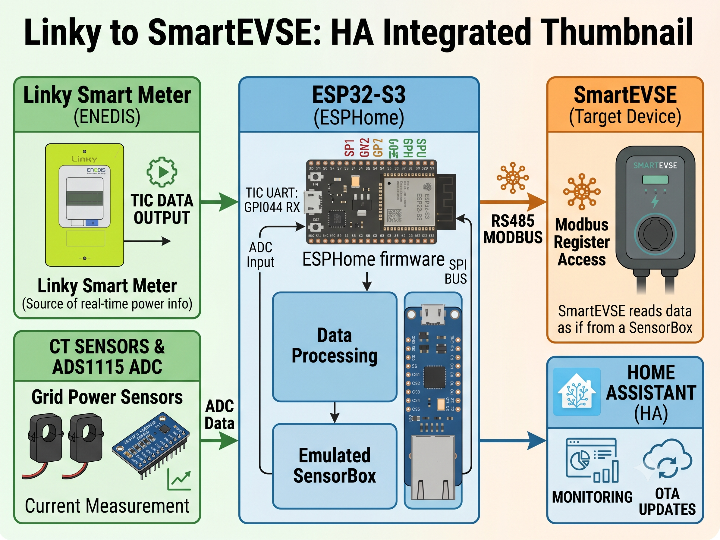
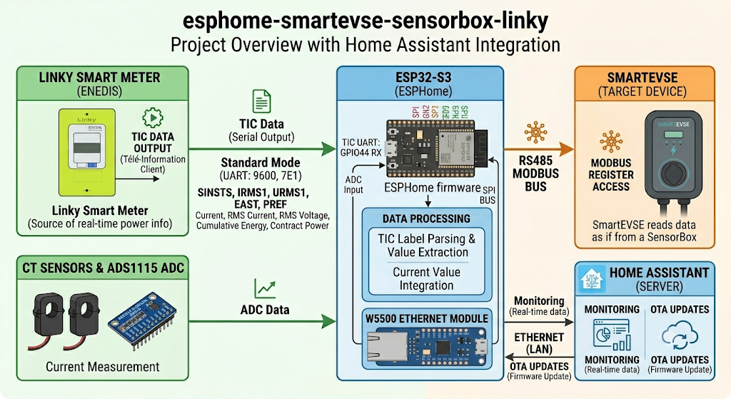
이 프로젝트는 ESPHome 기반으로 동작하는 SmartEVSE SensorBox 호환 프로젝트입니다. 입력 데이터는 크게 두 가지입니다. 첫 번째는 Linky 전력 계량기에서 나오는 TIC 데이터이고, 두 번째는 CT 센서와 ADS1115 ADC로 측정한 전류 데이터입니다. 프로젝트는 이 값을 읽어 SmartEVSE가 SensorBox-2에서 기대하는 register 주소에 맞춰 제공합니다.
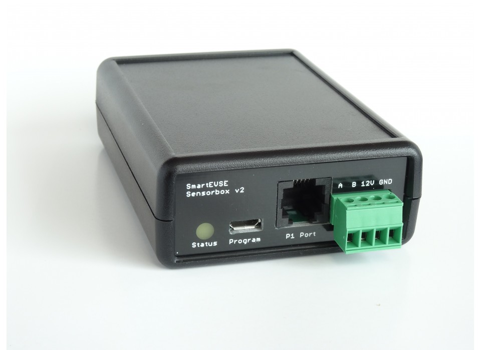
이미지 출처 : https://www.stegen.com/en/ev-products/129-smart-evse-sensorbox-v2.html
여기서 Linky는 프랑스 전력 배전망 운영사 Enedis가 사용하는 스마트 전력 계량기입니다. 일반적인 전력량계처럼 누적 전력량만 표시하는 장치가 아니라, 현재 전류, 전압, 피상전력, 계약 전력, 요금 구간 같은 데이터를 외부 장치가 읽을 수 있도록 디지털 출력 인터페이스를 제공합니다. 이 프로젝트에서는 Linky를 “전기차 충전 제어에 필요한 실시간 전력 정보의 원천”으로 사용합니다.
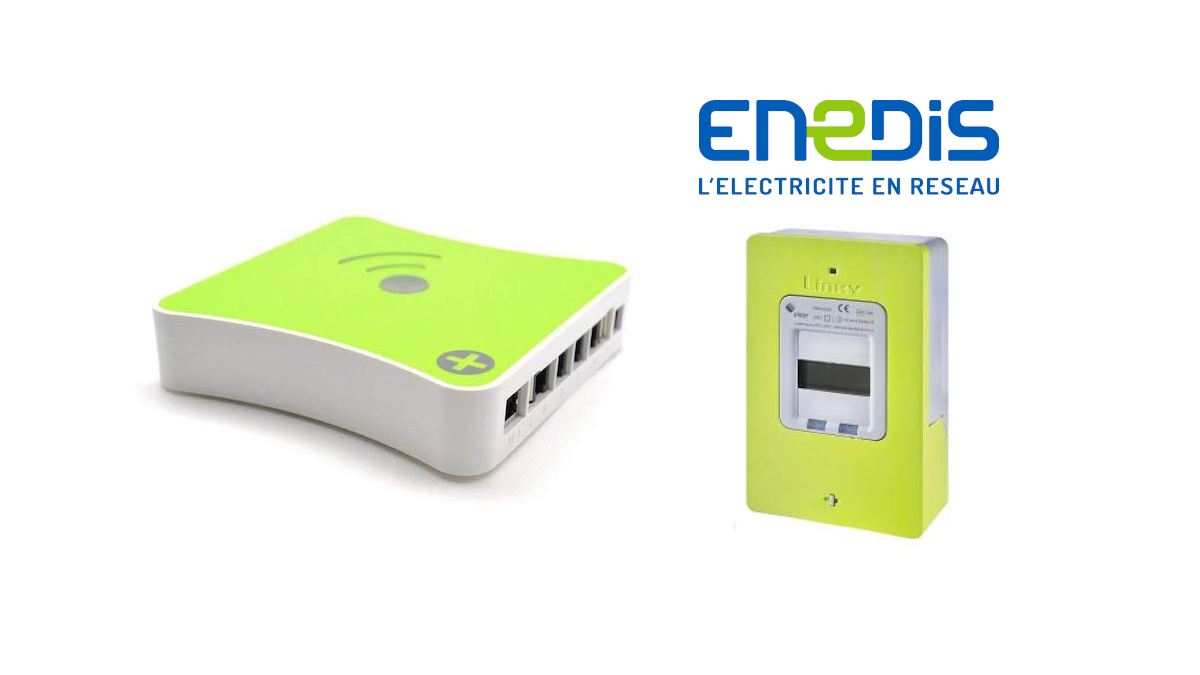
이미지 출처 : https://blog.domadoo.fr/83517-mise-a-jour-eedomus-support-du-compteur-linky-via-lapi-denedis/
TIC는 Télé-Information Client의 약자로, 한국어로 옮기면 “고객용 원격 정보 출력”에 가깝습니다. Linky 계량기 내부에서 측정된 전기 정보를 외부 장치가 읽을 수 있도록 주기적으로 내보내는 직렬 데이터 출력입니다. Enedis 문서는 TIC가 실시간 전기량, 요금 정보, 순간 전력 같은 데이터를 포함하며, 데이터가 라벨과 함께 순환적으로 전송된다고 설명합니다.
이 프로젝트에서 TIC 데이터는 ESP32-S3의 UART로 들어옵니다. README 예제에서는 Linky TIC를 GPIO44 RX, 9600 baud, 7 data bits, even parity, 1 stop bit의 standard mode로 설정합니다. 코드에서는 SINSTS, IRMS1, URMS1, EAST, PREF 같은 TIC 라벨을 읽어 전력, 전류, 전압, 누적 에너지, 계약 전력 값으로 사용합니다.
전기차 충전기 연동에서 중요한 부분은 단순히 값을 읽는 것이 아니라, SmartEVSE가 이해할 수 있는 SensorBox 형식으로 다시 제공하는 것입니다. SmartEVSE는 RS485 Modbus bus를 통해 SensorBox 값을 읽습니다. 이 프로젝트는 Linky TIC와 CT 측정값을 SmartEVSE SensorBox-2 주소 영역에 기록하므로, SmartEVSE 입장에서는 ESP32-S3 장치가 SensorBox처럼 동작합니다.
이미지 출처 : AI 생성
WIZnet이 들어가는 위치
이 프로젝트에서 사용되는 WIZnet 제품은 W5500입니다.
W5500은 SmartEVSE와 직접 통신하는 부품이 아닙니다. SmartEVSE와의 SensorBox 호환 데이터 교환은 RS485/UART 기반 Modbus slave bus가 담당합니다. W5500은 ESP32-S3-ETH 보드에서 Wi-Fi를 대체하는 유선 Ethernet 인터페이스로 사용됩니다. README에서도 ESP32-S3-Zero는 Wi-Fi를 사용하고, ESP32-S3-ETH는 Wi-Fi를 끄고 Ethernet W5500을 활성화하는 구성으로 구분합니다.
역할을 나누면 구조가 명확해집니다.
- Linky TIC: 계량기에서 실시간 전력 데이터를 가져오는 입력
- ADS1115 + CT 센서: 각 상의 전류를 보완 측정하는 아날로그 입력
- ESP32-S3: TIC 데이터와 CT 값을 읽고 SensorBox register로 변환
- RS485 Modbus: SmartEVSE가 SensorBox 데이터를 읽는 통신 경로
- W5500 Ethernet: ESPHome 장치의 OTA, 웹 서버, 상태 확인용 관리 네트워크
전기차 충전기 주변은 전력선, CT 배선, RS485 배선, 금속 enclosure가 함께 배치되는 경우가 많습니다. 이런 환경에서는 Wi-Fi보다 유선 Ethernet이 유지보수와 접근성 측면에서 유리합니다. W5500은 하드웨어 TCP/IP stack, SPI 인터페이스, 8개 socket, 32KB 내부 buffer를 제공하므로 ESP32-S3가 계측과 Modbus 처리에 집중하는 구조를 만들 수 있습니다.
구현 메모
이 저장소에서 확인되는 W5500 사용은 커스텀 W5500 드라이버 코드가 아니라 ESPHome YAML 설정입니다. C++ 컴포넌트는 W5500 socket을 직접 제어하지 않고, Linky/CT 값을 SensorBox 호환 Modbus register에 기록하는 역할을 담당합니다.
README.md의 ESP32-S3-ETH 예제에는 W5500 Ethernet 설정이 다음과 같이 포함되어 있습니다.
# ethernet:
#   type: W5500
#   clk_pin: GPIO13
#   mosi_pin: GPIO11
#   miso_pin: GPIO12
#   cs_pin: GPIO14
#   reset_pin: GPIO9
#   interrupt_pin: GPIO10
이 설정은 ESPHome의 Ethernet component에 W5500을 연결하는 부분입니다. ESPHome 문서에서도 SPI Ethernet 구성에는 clk_pin, mosi_pin, miso_pin, cs_pin, interrupt_pin, reset_pin 같은 항목이 사용된다고 설명합니다. 또한 SPI Ethernet 칩은 SPI 핀을 다른 장치와 공유하지 않는 것이 중요합니다.
SmartEVSE 호환성은 Ethernet 설정이 아니라 esphome/components/smartevse_sensorbox/smartevse_sensorbox.cpp의 Modbus publish 로직에서 만들어집니다.
write_u16(this->mb_smartevse_, 0x0100, static_cast<uint16_t>(this->ct_a_curr_a_)); // CT1
write_u16(this->mb_smartevse_, 0x0101, static_cast<uint16_t>(this->ct_b_curr_a_)); // CT2
write_u16(this->mb_smartevse_, 0x0102, static_cast<uint16_t>(this->ct_c_curr_a_)); // CT3

write_u16(this->mb_smartevse_, 0x0110, this->urms1_v_);
write_u16(this->mb_smartevse_, 0x0111, this->urms2_v_);
write_u16(this->mb_smartevse_, 0x0112, this->urms3_v_);
이 코드는 CT1, CT2, CT3 전류와 3상 전압값을 SmartEVSE가 읽을 수 있는 SensorBox-2 register 영역에 배치합니다. 따라서 충전기는 별도의 데이터 변환 없이 SensorBox와 유사한 방식으로 값을 읽을 수 있습니다.
총 피상전력은 Linky TIC 값을 우선 사용할지, CT 계산값을 사용할지 선택할 수 있습니다.
write_u32(this->mb_smartevse_, 0x0120,
          this->prefer_linky_power_ && this->sinsts_va_
          ? this->sinsts_va_
          : this->ct_total_va_);
이 부분은 전기차 충전 제어에서 중요합니다. prefer_linky_power가 활성화되어 있고 Linky의 SINSTS 값이 유효하면, CT 계산값 대신 계량기 기반 피상전력을 SmartEVSE에 제공합니다. CT 설치 방향이나 보정값이 아직 완전히 맞지 않은 현장에서는 Linky 값을 기준으로 운용하는 방식이 더 일관적일 수 있습니다.
실전 팁 / 주의점
- W5500 Ethernet이 정상이어도 SmartEVSE 연동이 자동으로 보장되지는 않습니다. SmartEVSE가 읽는 경로는 RS485 Modbus이므로 UART 핀, RS485 enable pin, slave address 설정을 별도로 확인해야 합니다.
- Linky TIC는 단순 UART 로그가 아니라 라벨이 붙은 계량기 데이터 스트림입니다.
SINSTS,IRMS,URMS,EAST같은 라벨이 어떤 전기량을 의미하는지 먼저 이해해야 합니다. - ESP32-S3-ETH 구성에서는 Wi-Fi를 끄고 Ethernet을 사용하는 설정을 명확히 해야 합니다. Wi-Fi와 Ethernet을 동시에 의심해야 하는 상태가 되면 문제 원인 추적이 어려워집니다.
- W5500은 SPI 기반 Ethernet 컨트롤러입니다.
CLK,MOSI,MISO,CS,RESET,INT핀을 보드 문서와 ESPHome 설정에서 동일하게 맞춰야 합니다. - CT 보정값은 CT 비율, burden resistor, 설치 방향에 따라 달라집니다. 예제값을 그대로 쓰기보다 실제 계량기 값과 비교해 보정하는 것이 안전합니다.
- RS485 배선은 A/B 극성, termination, GND 기준, 케이블 길이에 민감합니다. Ethernet 링크보다 Modbus 배선 문제가 먼저 나타날 수 있습니다.
- EVSE 주변 배선 작업은 전력 계통과 연결되므로 안전 기준을 지켜야 합니다. 계측 회로, 통신 회로, 충전 제어 회로를 분리해 검증하는 방식이 좋습니다.
FAQ
Q: 왜 이 프로젝트에서 W5500을 사용하나요?
A: W5500은 ESP32-S3-ETH 구성에서 Wi-Fi 대신 유선 Ethernet을 제공합니다. 전기차 충전기 주변처럼 금속 enclosure, 전력선, RS485 배선이 가까운 환경에서는 유선 링크가 OTA와 상태 확인에 더 안정적입니다.
Q: ESP32-S3에는 W5500을 어떻게 연결하나요?
A: ESPHome의 ethernet: 블록에서 type: W5500을 지정하고 SPI 핀을 설정합니다. 이 프로젝트의 예제는 GPIO13 CLK, GPIO11 MOSI, GPIO12 MISO, GPIO14 CS, GPIO9 RESET, GPIO10 INTERRUPT 구성을 사용합니다.
Q: W5500은 SmartEVSE와 직접 통신하나요?
A: 아닙니다. SmartEVSE와의 SensorBox 호환 통신은 RS485 Modbus slave bus가 담당합니다. W5500은 ESPHome 노드의 관리 네트워크를 담당하고, SmartEVSE 호환성은 C++ 코드의 Modbus register 변환 로직에서 만들어집니다.
Q: Linky와 TIC는 이 프로젝트에서 어떤 역할을 하나요?
A: Linky는 전력 데이터를 제공하는 계량기이고, TIC는 그 데이터를 외부 장치로 내보내는 직렬 정보 출력입니다. 이 프로젝트는 TIC에서 순간 피상전력, 전류, 전압, 누적 전력량 같은 값을 읽어 SmartEVSE가 사용할 수 있는 SensorBox register로 변환합니다.
Q: Wi-Fi 구성과 비교하면 W5500 구성의 장점은 무엇인가요?
A: Wi-Fi 구성도 기능 구현은 가능하지만, EVSE처럼 고정 설치되는 장비에서는 유선 Ethernet이 유지보수에 유리합니다. W5500을 사용하면 ESPHome OTA, 웹 서버, 상태 확인을 더 예측 가능한 네트워크 경로로 운영할 수 있습니다.
What the Project Does
This project is an ESPHome-based project compatible with the SmartEVSE SensorBox. It uses two main types of input data. The first is TIC data from the Linky electricity meter, and the second is current data measured using CT sensors and an ADS1115 ADC. The project reads these values and provides them at the register addresses expected by SmartEVSE SensorBox-2.
Image source: https://www.stegen.com/en/ev-products/129-smart-evse-sensorbox-v2.html
In this context, Linky is a smart electricity meter used by Enedis, the French electricity distribution network operator. Unlike a conventional electricity meter that only displays accumulated energy consumption, Linky provides a digital output interface that allows external devices to read data such as current, voltage, apparent power, subscribed power, and tariff information. In this project, Linky is used as the source of real-time power information needed for EV charging control.
Image source: https://blog.domadoo.fr/83517-mise-a-jour-eedomus-support-du-compteur-linky-via-lapi-denedis/
TIC stands for Télé-Information Client, which can be roughly translated as “customer tele-information output.” It is a serial data output that periodically sends electrical information measured inside the Linky meter so that external devices can read it. Enedis documentation explains that TIC includes data such as real-time electrical measurements, tariff information, and instantaneous power, and that the data is transmitted cyclically with labels.
In this project, TIC data enters the ESP32-S3 through UART. In the README example, Linky TIC is configured in standard mode using GPIO44 as RX, 9600 baud, 7 data bits, even parity, and 1 stop bit. In the code, TIC labels such as SINSTS, IRMS1, URMS1, EAST, and PREF are read and used as values for power, current, voltage, accumulated energy, and subscribed power.
The important point in EV charger integration is not just reading these values, but providing them again in a SensorBox format that SmartEVSE can understand. SmartEVSE reads SensorBox values through an RS485 Modbus bus. This project writes Linky TIC data and CT measurement values into the SmartEVSE SensorBox-2 address range, so from the SmartEVSE perspective, the ESP32-S3 device behaves like a SensorBox.
Image source: AI-generated
Similar Project
https://maker.wiznet.io/Benjamin/projects/esp32%2Djsy%2Denergy%2Dmeter%2Dgateway%2Dwith%2Dw5500%2Dsupport/
Both projects are similar in that they apply W5500 Ethernet to an ESP32-based power data processing device. However, SmartEVSE SensorBox Linky is a SensorBox-compatible device for EV charging control, while JSY Energy Meter Gateway is a general-purpose energy gateway that provides power data over the network.
Similarities
| Item | Similarity |
|---|---|
| Platform | Both projects use ESP32-family boards. |
| Power data | Both handle measured data such as voltage, current, power, and energy. |
| W5500 | Both support W5500 Ethernet configurations in an ESP32-S3 environment. |
| Installation environment | Both are close to fixed-installation power or energy monitoring devices. |
| Wi-Fi replacement | Using W5500 enables a more stable wired network configuration than Wi-Fi. |
| Single-phase / three-phase support | Both projects are structured to handle single-phase or three-phase power data. |
Differences
| Item | SmartEVSE SensorBox Linky Project | ESP32 JSY Energy Meter Gateway |
|---|---|---|
| Main purpose | SensorBox replacement device read by SmartEVSE | Exposes JSY power meter data through network APIs |
| End user | SmartEVSE-based EV charging system | Home automation, dashboard, Shelly-compatible integration |
| Input data | Linky TIC + ADS1115 CT measurements | JSY power meter UART data |
| Output method | RS485 Modbus slave bus | Web dashboard, REST API, Shelly API, UDP |
| W5500 role | Ethernet for ESPHome management network | Provides the energy data service over wired Ethernet |
| SmartEVSE integration | Directly related | Not intended as a direct SmartEVSE SensorBox-compatible device |
| Development method | ESPHome external component + YAML configuration | Arduino/PlatformIO-based firmware |
| Main protocols | TIC UART, I2C ADS1115, RS485 Modbus | UART, HTTP REST, Shelly-compatible API, UDP |
| Data consumer | SmartEVSE controller | Browser, home automation system, UDP listener, Shelly-compatible client |
Where WIZnet Fits
The WIZnet product used in this project is the W5500.
The W5500 does not communicate directly with SmartEVSE. SensorBox-compatible data exchange with SmartEVSE is handled by the RS485/UART-based Modbus slave bus. The W5500 is used as a wired Ethernet interface that replaces Wi-Fi on the ESP32-S3-ETH board. The README also distinguishes between the ESP32-S3-Zero configuration, which uses Wi-Fi, and the ESP32-S3-ETH configuration, which disables Wi-Fi and enables W5500 Ethernet.
The system structure becomes clearer when the roles are separated:
- Linky TIC: Input that retrieves real-time power data from the electricity meter
- ADS1115 + CT sensors: Analog input that supplements current measurement for each phase
- ESP32-S3: Reads TIC data and CT values, then converts them into SensorBox registers
- RS485 Modbus: Communication path through which SmartEVSE reads SensorBox data
- W5500 Ethernet: Management network for ESPHome OTA, web server access, and status checking
EV charger environments often include power lines, CT wiring, RS485 wiring, and metal enclosures in close proximity. In this kind of environment, wired Ethernet is often better than Wi-Fi in terms of maintainability and accessibility. Since the W5500 provides a hardware TCP/IP stack, SPI interface, eight sockets, and a 32 KB internal buffer, it allows the ESP32-S3 to focus on measurement and Modbus processing.
Implementation Notes
The W5500 usage confirmed in this repository is not a custom W5500 driver implementation, but an ESPHome YAML configuration. The C++ component does not directly control W5500 sockets. Instead, it records Linky and CT values into SensorBox-compatible Modbus registers.
The ESP32-S3-ETH example in README.md includes the following W5500 Ethernet configuration:
# ethernet:
#   type: W5500
#   clk_pin: GPIO13
#   mosi_pin: GPIO11
#   miso_pin: GPIO12
#   cs_pin: GPIO14
#   reset_pin: GPIO9
#   interrupt_pin: GPIO10
This setting connects the W5500 to ESPHome’s Ethernet component. ESPHome documentation also explains that SPI Ethernet configurations use fields such as clk_pin, mosi_pin, miso_pin, cs_pin, interrupt_pin, and reset_pin. It is also important not to share the SPI pins used by the SPI Ethernet chip with other devices.
SmartEVSE compatibility is created not by the Ethernet configuration, but by the Modbus publish logic in esphome/components/smartevse_sensorbox/smartevse_sensorbox.cpp.
write_u16(this->mb_smartevse_, 0x0100, static_cast<uint16_t>(this->ct_a_curr_a_)); // CT1
write_u16(this->mb_smartevse_, 0x0101, static_cast<uint16_t>(this->ct_b_curr_a_)); // CT2
write_u16(this->mb_smartevse_, 0x0102, static_cast<uint16_t>(this->ct_c_curr_a_)); // CT3

write_u16(this->mb_smartevse_, 0x0110, this->urms1_v_);
write_u16(this->mb_smartevse_, 0x0111, this->urms2_v_);
write_u16(this->mb_smartevse_, 0x0112, this->urms3_v_);
This code places CT1, CT2, and CT3 current values, as well as three-phase voltage values, into the SensorBox-2 register area that SmartEVSE can read. As a result, the charger can read the values in a SensorBox-like way without requiring separate data conversion.
For total apparent power, the project can choose whether to prioritize the Linky TIC value or the CT-calculated value.
write_u32(this->mb_smartevse_, 0x0120,
          this->prefer_linky_power_ && this->sinsts_va_
          ? this->sinsts_va_
          : this->ct_total_va_);
This part is important for EV charging control. If prefer_linky_power is enabled and the Linky SINSTS value is valid, the project provides SmartEVSE with meter-based apparent power instead of the CT-calculated value. In installations where CT direction or calibration values are not yet fully tuned, using the Linky value as the reference can provide more consistent operation.
Practical Tips / Pitfalls
- Even if W5500 Ethernet is working correctly, SmartEVSE integration is not automatically guaranteed. The path read by SmartEVSE is RS485 Modbus, so UART pins, the RS485 enable pin, and the slave address must be checked separately.
- Linky TIC is not just a simple UART log. It is a labeled meter data stream. Labels such as
SINSTS,IRMS,URMS, andEASTshould be understood before using the data. - In the ESP32-S3-ETH configuration, it should be clear that Wi-Fi is disabled and Ethernet is used. If both Wi-Fi and Ethernet are considered at the same time during debugging, root cause analysis becomes harder.
- The W5500 is an SPI-based Ethernet controller.
CLK,MOSI,MISO,CS,RESET, andINTpins must match between the board documentation and the ESPHome configuration. - CT calibration values vary depending on the CT ratio, burden resistor, and installation direction. It is safer to calibrate against actual meter readings rather than using the example values as-is.
- RS485 wiring is sensitive to A/B polarity, termination, ground reference, and cable length. Modbus wiring issues may appear before Ethernet link issues.
- EVSE wiring work is connected to the power system, so safety requirements must be followed. It is better to verify the measurement circuit, communication circuit, and charging control circuit separately.
FAQ
Q: Why does this project use the W5500?
A: The W5500 provides wired Ethernet instead of Wi-Fi in the ESP32-S3-ETH configuration. In an EV charger environment where metal enclosures, power lines, and RS485 wiring are close together, a wired link is more stable for OTA updates and status monitoring.
Q: How is the W5500 connected to the ESP32-S3?
A: In ESPHome, type: W5500 is specified in the ethernet: block, and the SPI pins are configured. The example in this project uses GPIO13 for CLK, GPIO11 for MOSI, GPIO12 for MISO, GPIO14 for CS, GPIO9 for RESET, and GPIO10 for INTERRUPT.
Q: Does the W5500 communicate directly with SmartEVSE?
A: No. SensorBox-compatible communication with SmartEVSE is handled by the RS485 Modbus slave bus. The W5500 handles the ESPHome node’s management network, while SmartEVSE compatibility is created by the Modbus register conversion logic in the C++ code.
Q: What roles do Linky and TIC play in this project?
A: Linky is the meter that provides power data, and TIC is the serial information output that sends that data to external devices. This project reads values such as instantaneous apparent power, current, voltage, and accumulated energy from TIC, then converts them into SensorBox registers that SmartEVSE can use.
Q: What is the advantage of the W5500 configuration compared with Wi-Fi?
A: Wi-Fi can also implement the function, but wired Ethernet is more suitable for maintenance in fixed EVSE installations. With the W5500, ESPHome OTA, web server access, and status monitoring can run over a more predictable network path.
-
Github Code
