


ESP32-Watchman
ESP32-Watchman
Espressif - ESP32
x 1


WIZnet - W5500
x 1
프로젝트 개요
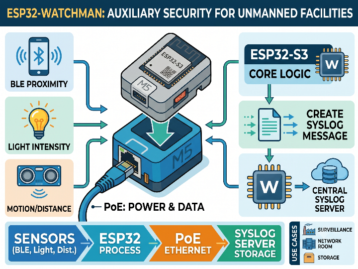
ESP32-Watchman은 ESP32-S3 기반의 M5Stack Atom S3 Lite와 WIZnet W5500이 탑재된 Atomic PoE Base를 사용해 무인 시설 주변의 이상 징후를 감지하는 프로젝트입니다. 카메라를 대체하기보다는 Bluetooth 기기의 접근, 조도 변화, 물체의 움직임을 탐지해 중앙 Syslog 서버로 전달하는 보조 보안 장치에 가깝습니다.
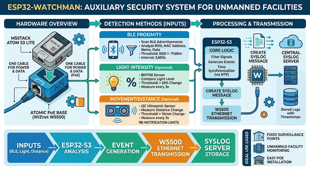
이미지 출처 : AI 생성
ESP32-S3는 일정한 주기로 주변 BLE 광고 패킷을 검색합니다. 감지된 장치의 신호 세기가 설정된 RSSI 기준보다 강한 경우에만 MAC 주소, 제조사 데이터, 서비스 UUID, 장치 이름 등을 분석합니다. 같은 장치가 짧은 시간 안에 반복해서 탐지되면 로그가 과도하게 쌓이지 않도록 재감지 제한 시간도 적용합니다. 기본 설정은 RSSI -71dBm, 재감지 간격 3,600초이며 필요에 따라 시리얼 콘솔에서 변경할 수 있습니다.
선택적으로 BH1750 기반 조도 센서 또는 I2C 초음파 거리 센서를 연결할 수 있습니다. 조도 센서는 이전 측정값과 비교해 밝기가 일정 비율 이상 변했을 때 이벤트를 생성합니다. 초음파 센서는 거리 변화가 설정된 범위를 넘으면 움직임으로 판단합니다. 기본값은 조도 변화 20%, 거리 변화 10mm이며, 두 센서 모두 3초 간격으로 측정합니다. 센서 노이즈에 따른 반복 경보를 줄이기 위한 재알림 제한도 포함되어 있습니다.
감지 결과는 ESP32-S3에서 Syslog 메시지로 작성되며, W5500을 통해 중앙 서버로 전송됩니다. NTP 서버에서 받은 시간을 메시지에 포함하므로 여러 감시 노드의 이벤트를 동일한 시간 기준으로 비교할 수 있습니다.
전체 데이터 흐름은 다음과 같습니다.
BLE·조도·거리 입력 → ESP32-S3 분석 → 이벤트 생성 → W5500 Ethernet 전송 → Syslog 서버 저장
Atomic PoE Base를 사용하면 하나의 Ethernet 케이블로 네트워크와 전원을 함께 공급할 수 있습니다. 따라서 별도의 전원 어댑터를 설치하기 어려운 출입구, 창고, 통신실, 서버실 등의 고정형 감시 지점에 배치하기 좋습니다.
WIZnet W5500의 역할
이 프로젝트에서 사용되는 WIZnet 제품은 W5500입니다. W5500은 SPI로 ESP32-S3와 연결되며, Ethernet MAC·PHY와 하드웨어 TCP/IP 스택을 제공합니다. 최대 80MHz SPI, 8개의 하드웨어 소켓, 32KB 송수신 버퍼를 지원하므로 외부 MCU가 모든 TCP/IP 처리를 소프트웨어로 수행하지 않아도 됩니다.
프로젝트에서 W5500이 담당하는 기능은 다음과 같습니다.
NTP 서버와 통신해 이벤트 기록에 사용할 시간을 동기화합니다.
BLE 및 센서 감지 결과를 UDP Syslog 메시지로 전송합니다.
Ethernet 링크 상태를 확인해 네트워크 연결 여부를 장치 상태 LED로 표시합니다.
ESP32-S3는 BLE 검색, 장치 분류, 센서 데이터 분석에 집중하고 W5500은 유선 네트워크 전송을 담당합니다. 이러한 구조는 감지 로직과 통신 처리를 분리해 펌웨어 구성을 단순하게 만듭니다. 또한 Wi-Fi 연결이나 무선 채널 상태에 의존하지 않으므로 설치 위치가 고정된 감시 노드에 적합합니다.
PoE 전원 변환은 W5500 자체 기능이 아닙니다. W5500은 Ethernet 통신을 처리하며, Atomic PoE Base의 별도 전원 회로가 케이블에서 전력을 공급합니다.
구현 메모
W5500 SPI 및 네트워크 초기화
파일: ESP32-Watchman.ino
핀 설정: Config.h
SPI.begin(ETH_SPI_SCK, ETH_SPI_MISO, ETH_SPI_MOSI, -1);
Ethernet.init(ETH_PHY_CS);
Ethernet.begin(mac, configIp, configDns, configGateway, configSubnet);
이 코드는 ESP32-S3의 SPI 버스를 시작하고 W5500의 CS 핀을 Arduino Ethernet 라이브러리에 등록합니다. 이후 저장된 IP 주소, DNS, 게이트웨이, 서브넷 정보를 적용합니다.
기본 SPI 핀은 다음과 같습니다.
SCK: GPIO 5
MISO: GPIO 7
MOSI: GPIO 8
CS: GPIO 6
현재 코드는 DHCP가 아닌 정적 IP 구성을 사용합니다. 설정값은 최초 부팅 시 시리얼 콘솔에서 입력하며 비휘발성 메모리에 저장됩니다. 부팅 후에는 Ethernet.hardwareStatus()와 Ethernet.linkStatus()를 검사해 W5500 하드웨어와 케이블 연결 상태를 확인합니다.
UDP Syslog 이벤트 전송
파일: ESP32-Watchman.ino
syslogUdp.beginPacket(configSyslog, SYSLOG_PORT);
syslogUdp.print(syslogMessage);
syslogUdp.endPacket();
감지 이벤트는 NTP 시간과 장치 호스트 이름이 포함된 Syslog 메시지로 구성된 뒤 UDP 514번 포트로 전송됩니다. 메시지 버퍼는 1,420바이트로 제한되며, 이 범위를 넘는 내용은 잘라서 처리합니다.
UDP 방식은 연결 과정이 간단하지만 전송 성공 확인, 재전송, 암호화, 서버 인증을 제공하지 않습니다. 코드에서도 이러한 보완 기능은 확인되지 않습니다. 따라서 실제 보안 시설에서는 장치와 Syslog 서버를 별도 VLAN에 배치하고, 방화벽이나 ACL로 허용 목적지와 포트를 제한하는 구성이 필요합니다. 이는 원본 구현을 운영 환경에 적용할 때 고려해야 할 보완 사항입니다.
실용적인 팁과 주의사항
SPI 핀을 먼저 확인하셔야 합니다. 다른 ESP32-S3 보드나 별도 W5500 모듈을 사용할 경우 Config.h의 핀 번호를 실제 배선에 맞게 변경해야 합니다.
장치별로 고유한 네트워크 설정을 사용하셔야 합니다. 여러 노드를 설치할 때 IP 주소와 호스트 이름이 중복되면 로그 출처를 구분하기 어렵습니다.
BLE 감도는 설치 장소에서 조정하시는 것이 좋습니다. RSSI 기준이 너무 낮으면 인접 공간의 장치까지 탐지하고, 너무 높으면 실제 접근 장치를 놓칠 수 있습니다.
수동 BLE 검색을 기본으로 사용하시는 편이 안전합니다. 능동 검색을 활성화하면 새 장치에 직접 연결해 서비스 정보를 요청하므로 불필요한 무선 상호작용이 늘어날 수 있습니다. 원본 설정에서는 능동 검색이 비활성화되어 있습니다.
링크 장애 복구 기능을 추가하는 것이 좋습니다. 현재 코드는 Ethernet 하드웨어나 링크를 찾지 못하면 대기 상태에 머뭅니다. 장기 무인 운용에는 Watchdog, 링크 재초기화, 이벤트 임시 저장 기능이 필요합니다.
Syslog 통신망을 분리하시는 것이 좋습니다. UDP 514번 포트를 전체 사내망에 개방하기보다 전용 VLAN과 ACL을 사용해 감시 노드에서 지정된 서버로만 접근하도록 구성하는 편이 안전합니다.
USB와 PoE를 동시에 연결할 때 주의하셔야 합니다. 원본 README는 펌웨어 업로드와 설정을 마친 뒤 USB를 분리하고 PoE Ethernet을 연결하도록 안내합니다.
유사 프로젝트
https://maker.wiznet.io/Lihan__/projects/securitysensor4tomqtt/?page=3&serob=rd&serterm=year
유사점
| 항목 | 공통점 |
|---|---|
| 목적 | 두 프로젝트 모두 현장의 보안 상태를 감지하고, 이벤트를 네트워크를 통해 중앙 시스템으로 전달합니다. |
| 네트워크 | WIZnet Ethernet 칩의 하드웨어 TCP/IP 기능을 사용해 유선 네트워크를 구성합니다. |
| 동작 방식 | 센서 또는 주변 장치의 상태를 MCU에서 판단한 뒤, 필요한 이벤트만 서버로 전송합니다. |
| 운용 형태 | 장시간 상시 작동하는 원격 보안 감시 노드를 목표로 합니다. |
| 확장성 | 여러 장치를 중앙 서버에서 구분하고 통합 관리할 수 있는 구조입니다. |
차이점
| 항목 | ESP32-Watchman | SecuritySensor4ToMQTT |
|---|---|---|
| MCU | ESP32-S3 | ATmega2560급 Arduino |
| WIZnet 칩 | W5500 | W5100 |
| 감지 대상 | BLE 기기, 조도 변화, 거리 변화 | 유선 보안 센서 4개 |
| 감지 방식 | 무선 검색 및 환경 센서 측정 | EOL 저항의 아날로그 값을 측정 |
| 상태 구분 | 새 BLE 장치, 반복 접근, 밝기·거리 변화 | 정상, 변조, 경보, 경보+변조, 단락, 단선의 6가지 상태 |
| 전송 방식 | UDP 기반 Syslog | TCP 기반 MQTT |
| 서버 연동 | Syslog 수집·보안 관제 시스템 | Home Assistant, Node-RED, MQTT 브로커 |
| 전원 구성 | Atomic PoE Base로 Ethernet과 전원 통합 | Arduino와 Ethernet 하드웨어에 별도 전원 필요 |
| 주요 강점 | 비접촉 방식으로 사람이나 전자기기의 접근 징후 감지 | 센서 배선의 절단·단락·변조까지 감지 가능 |
FAQ
Q: 이 프로젝트에서 W5500을 사용하는 이유는 무엇인가요?
A: ESP32-S3가 BLE 검색과 센서 분석을 수행하는 동안 W5500이 Ethernet 통신을 처리할 수 있기 때문입니다. 하드웨어 TCP/IP 스택과 전용 송수신 버퍼를 사용하므로 네트워크 처리 구조를 단순하게 구성할 수 있습니다. Atomic PoE Base와 결합하면 전원과 통신도 하나의 케이블로 공급할 수 있습니다.
Q: W5500은 ESP32-S3와 어떻게 연결되나요?
A: SPI 인터페이스로 연결됩니다. 이 프로젝트에서는 GPIO 5, 7, 8, 6을 각각 SCK, MISO, MOSI, CS로 사용하며, SPI.begin()과 Ethernet.init()으로 초기화합니다.
Q: W5500은 감시 시스템에서 어떤 기능을 담당하나요?
A: NTP 시간 동기화와 UDP Syslog 전송을 담당합니다. BLE 기기 탐지, 장치 분류, 조도 및 거리 변화 분석은 ESP32-S3에서 수행합니다.
Q: 초보자도 구현할 수 있나요?
A: Arduino IDE에서 ESP32 보드를 사용해 본 경험이 있다면 기본 펌웨어는 따라 하실 수 있습니다. 다만 정적 IP, NTP, UDP, Syslog, PoE에 대한 기초 지식이 필요하므로 전체 시스템 구성은 중급 수준에 가깝습니다. 원본 프로젝트는 Arduino 환경 설정과 시리얼 콘솔 기반 초기 설정 절차를 제공합니다.
Q: Wi-Fi와 비교했을 때 W5500 Ethernet은 어떤 차이가 있나요?
A: Wi-Fi는 케이블 없이 설치할 수 있지만 무선 간섭, AP 재연결, 인증 정보 관리가 필요합니다. W5500 기반 Ethernet은 배선이 필요하지만 통신 경로를 고정하고 스위치 포트, VLAN, ACL을 이용해 접근 범위를 제어하기 쉽습니다. 따라서 이동형 장치에는 Wi-Fi가 편리하고, 고정된 무인 시설의 감시 노드에는 PoE Ethernet 구성이 관리하기 수월합니다.
Project Overview
ESP32-Watchman is a project designed to detect unusual activity around unattended facilities using an ESP32-S3-based M5Stack Atom S3 Lite and an Atomic PoE Base equipped with the WIZnet W5500. Rather than replacing a camera surveillance system, it serves as a supplementary security device that detects nearby Bluetooth devices, changes in ambient light, and object movement, then forwards the resulting events to a central Syslog server.
Image source : AI Generated
The ESP32-S3 periodically scans for nearby BLE advertising packets. It analyzes information such as the MAC address, manufacturer data, service UUIDs, and device name only when the detected device’s signal strength exceeds the configured RSSI threshold. A rediscovery interval is also applied to prevent excessive log generation when the same device is detected repeatedly within a short period. The default settings are an RSSI threshold of -71 dBm and a rediscovery interval of 3,600 seconds, both of which can be changed through the serial console.
An optional BH1750-based ambient light sensor or I2C ultrasonic distance sensor can also be connected. The light sensor generates an event when the brightness changes by more than a specified percentage compared with the previous reading. The ultrasonic sensor interprets movement when the distance changes beyond a configured threshold. The default thresholds are a 20% change in brightness and a 10 mm change in distance. Both sensors are sampled every three seconds. A notification suppression interval is also included to reduce repeated alerts caused by sensor noise.
Detection results are formatted as Syslog messages by the ESP32-S3 and transmitted to the central server through the W5500. Because each message includes a timestamp obtained from an NTP server, events from multiple monitoring nodes can be compared using the same time reference.
The overall data flow is as follows:
BLE, light, and distance input → ESP32-S3 analysis → Event generation → W5500 Ethernet transmission → Syslog server storage
The Atomic PoE Base allows both network connectivity and power to be delivered through a single Ethernet cable. This makes the device suitable for fixed monitoring points such as entrances, warehouses, telecommunications rooms, and server rooms where installing a separate power adapter may be difficult.
Role of the WIZnet W5500
The WIZnet product used in this project is the W5500. It connects to the ESP32-S3 over SPI and provides an Ethernet MAC, PHY, and hardware TCP/IP stack. With support for SPI speeds of up to 80 MHz, eight hardware sockets, and 32 KB of transmit and receive buffer memory, it allows the external MCU to avoid handling the entire TCP/IP stack in software.
The W5500 performs the following functions in this project:
It communicates with an NTP server to synchronize the time used for event logging.
It transmits BLE and sensor detection results as UDP Syslog messages.
It checks the Ethernet link status and indicates the network connection state through the device status LED.
The ESP32-S3 focuses on BLE scanning, device classification, and sensor data analysis, while the W5500 handles wired network communication. This division separates detection logic from network processing and simplifies the firmware architecture. It also avoids dependence on Wi-Fi connectivity or wireless channel conditions, making the system suitable for monitoring nodes installed in fixed locations.
PoE power conversion is not a function of the W5500 itself. The W5500 handles Ethernet communication, while a separate power circuit on the Atomic PoE Base extracts power from the Ethernet cable.
Implementation Notes
W5500 SPI and Network Initialization
File: ESP32-Watchman.ino
Pin configuration: Config.h
SPI.begin(ETH_SPI_SCK, ETH_SPI_MISO, ETH_SPI_MOSI, -1);
Ethernet.init(ETH_PHY_CS);
Ethernet.begin(mac, configIp, configDns, configGateway, configSubnet);
This code starts the ESP32-S3 SPI bus and registers the W5500 chip-select pin with the Arduino Ethernet library. It then applies the stored IP address, DNS server, gateway, and subnet mask.
The default SPI pins are:
SCK: GPIO 5
MISO: GPIO 7
MOSI: GPIO 8
CS: GPIO 6
The current implementation uses a static IP configuration rather than DHCP. The network settings are entered through the serial console during the initial boot and stored in non-volatile memory. After startup, the firmware checks Ethernet.hardwareStatus() and Ethernet.linkStatus() to verify the W5500 hardware and Ethernet cable connection.
UDP Syslog Event Transmission
File: ESP32-Watchman.ino
syslogUdp.beginPacket(configSyslog, SYSLOG_PORT);
syslogUdp.print(syslogMessage);
syslogUdp.endPacket();
Each detection event is formatted as a Syslog message containing the NTP timestamp and device hostname, then transmitted over UDP port 514. The message buffer is limited to 1,420 bytes, and content exceeding this size is truncated.
UDP is simple to use because it does not require a connection-establishment process. However, it does not provide delivery confirmation, retransmission, encryption, or server authentication. The source code does not include additional mechanisms to compensate for these limitations.
For deployment in an actual security facility, the device and Syslog server should therefore be placed on a separate VLAN. A firewall or ACL should restrict traffic to the required destination and port. These are important operational improvements when adapting the original implementation for a production environment.
Practical Tips and Considerations
Check the SPI pins before deployment. When using a different ESP32-S3 board or a separate W5500 module, update the pin definitions in Config.h to match the actual wiring.
Assign unique network settings to each device. When deploying multiple nodes, duplicated IP addresses or hostnames will make it difficult to identify the source of each log message.
Adjust BLE sensitivity at the installation site. If the RSSI threshold is too low, devices in adjacent areas may be detected. If it is too high, nearby devices that should be monitored may be missed.
Use passive BLE scanning by default. Active scanning directly connects to newly detected devices to request service information, which can create unnecessary wireless interaction. Active scanning is disabled in the original configuration.
Add Ethernet link recovery mechanisms. The current code remains in a waiting state when the Ethernet hardware or link is unavailable. A watchdog, link reinitialization routine, and temporary local event storage are recommended for long-term unattended operation.
Separate the Syslog network. Instead of exposing UDP port 514 across the entire internal network, use a dedicated VLAN and ACLs so that monitoring nodes can communicate only with the designated server.
Use caution when connecting USB and PoE at the same time. The original README instructs users to disconnect USB after firmware upload and configuration, then connect the PoE Ethernet cable.
Similar Project
https://maker.wiznet.io/Lihan__/projects/securitysensor4tomqtt/?page=3&serob=rd&serterm=year
Similarities
| Category | Shared Characteristics |
|---|---|
| Purpose | Both projects detect security-related conditions at a site and transmit events to a central system over a network. |
| Network | Both use the hardware TCP/IP capabilities of a WIZnet Ethernet chip to provide wired network connectivity. |
| Operating method | An MCU evaluates the status of sensors or nearby devices and sends only relevant events to the server. |
| Deployment model | Both are designed as remote security monitoring nodes intended for continuous, long-term operation. |
| Scalability | Both support architectures in which multiple devices can be identified and centrally managed by a server. |
Differences
| Category | ESP32-Watchman | SecuritySensor4ToMQTT |
|---|---|---|
| MCU | ESP32-S3 | ATmega2560-class Arduino |
| WIZnet chip | W5500 | W5100 |
| Detection targets | BLE devices, changes in ambient light, and distance changes | Four wired security sensors |
| Detection method | Wireless scanning and environmental sensor measurements | Analog measurement of EOL resistance |
| State classification | New BLE device, repeated approach, and changes in brightness or distance | Six states: normal, tamper, alarm, alarm with tamper, short circuit, and open circuit |
| Transport protocol | UDP-based Syslog | TCP-based MQTT |
| Server integration | Syslog collection and security monitoring systems | Home Assistant, Node-RED, and MQTT brokers |
| Power configuration | Ethernet and power are integrated through the Atomic PoE Base | Separate power is required for the Arduino and Ethernet hardware |
| Main strength | Contactless detection of people or electronic devices approaching the monitored area | Detection of sensor wire cuts, short circuits, and tampering |
FAQ
Q: Why is the W5500 used in this project?
A: The W5500 handles Ethernet communication while the ESP32-S3 performs BLE scanning and sensor analysis. Its hardware TCP/IP stack and dedicated transmit and receive buffers simplify the network architecture. When combined with the Atomic PoE Base, it also allows both power and communication to be delivered through a single cable.
Q: How is the W5500 connected to the ESP32-S3?
A: It is connected through the SPI interface. This project uses GPIO 5, 7, 8, and 6 for SCK, MISO, MOSI, and CS, respectively. The interface is initialized using SPI.begin() and Ethernet.init().
Q: What does the W5500 do in the monitoring system?
A: It handles NTP time synchronization and UDP Syslog transmission. BLE device detection, device classification, and analysis of light and distance changes are performed by the ESP32-S3.
Q: Can beginners build this project?
A: Users with previous experience using ESP32 boards in the Arduino IDE should be able to follow the basic firmware setup. However, knowledge of static IP configuration, NTP, UDP, Syslog, and PoE is required, so configuring the complete system is closer to an intermediate-level task. The original project provides Arduino environment setup instructions and an initial configuration procedure through the serial console.
Q: How does W5500 Ethernet compare with Wi-Fi?
A: Wi-Fi allows installation without network cabling, but it requires management of wireless interference, access point reconnection, and authentication credentials. W5500-based Ethernet requires cabling, but it provides a fixed communication path and makes it easier to control access through switch ports, VLANs, and ACLs. Wi-Fi is convenient for mobile devices, while PoE Ethernet is generally easier to manage for fixed monitoring nodes in unattended facilities.
-
Github Code


