


ESP32-S3-OSC-8Relay
ESP32-S3-OSC-8Relay
Espressif - ESP32
x 1


WIZnet - W5500
x 1
Project Overview
Waveshare ESP32-S3-ETH-8DI-8RO 보드에서 OSC UDP 메시지로 8개 릴레이를 제어하는 Industrial IoT용 펌웨어입니다. OSC는 오디오, 미디어, 자동화 장비에서 제어 명령을 주소 기반 메시지로 주고받기 위한 프로토콜이며, 이 프로젝트에서는 릴레이 번호와 ON/OFF 상태를 전달하는 명령 형식으로 사용됩니다.
WIZnet W5500은 릴레이 제어 명령을 받는 유선 Ethernet 인터페이스로 사용되고, Wi-Fi는 설정용 Web UI에 분리됩니다. 외부 제어 장비는 Ethernet을 통해 OSC UDP 패킷을 전송하고, 펌웨어는 /relay/1부터 /relay/8까지의 개별 릴레이 주소와 /relay/all 전체 제어 주소를 해석해 릴레이 상태를 반영합니다.
실제 릴레이 출력은 PCA9554 I2C expander를 통해 처리됩니다. 이 구조의 핵심은 제어 경로와 설정 경로를 분리한 점입니다. 릴레이 동작에 직접 영향을 주는 OSC 트래픽은 W5500 유선 Ethernet으로 고정하고, 장치 설정은 Wi-Fi AP 기반 Web UI에서 수행합니다. 원본 README도 W5500 Ethernet 기반 OSC 제어와 Wi-Fi Web UI 구성을 함께 설명합니다.
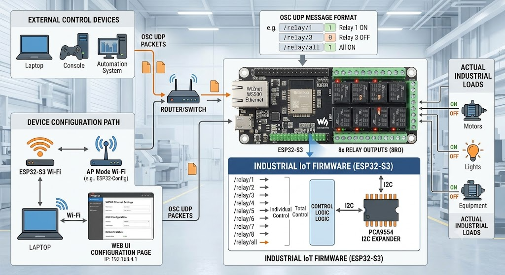
이미지 출처 : AI 생성
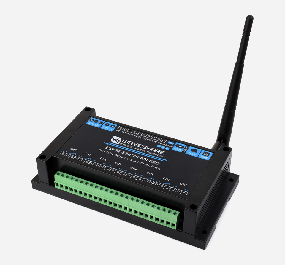
이미지 출처 : https://www.waveshare.com/esp32-s3-eth-8di-8ro.htm
Where WIZnet Fits
이 프로젝트에서 사용된 WIZnet 제품은 W5500입니다. W5500은 ESP32-S3와 SPI로 연결되며, OSC UDP 명령을 수신하는 Ethernet 컨트롤러 역할을 합니다.
릴레이 제어는 짧은 명령을 빠르게 받아 물리 출력으로 반영해야 합니다. W5500은 하드웨어 TCP/IP 오프로드, 내부 버퍼, 다중 소켓 구조를 제공하므로 ESP32-S3가 네트워크 처리에 과도하게 묶이지 않고 OSC 파싱, 릴레이 상태 관리, Web UI, watchdog, 설정 저장 로직을 함께 수행할 수 있습니다.
이 프로젝트에서 W5500은 단순한 네트워크 연결 장치가 아닙니다. 릴레이 제어용 실시간 명령 경로를 담당하는 전용 유선 인터페이스입니다. 그래서 Wi-Fi보다 예측 가능한 통신 경로가 필요한 Industrial IoT 릴레이 컨트롤러에 잘 맞습니다.
Implementation Notes
src/network_mgr.cpp — W5500 SPI 및 Ethernet 초기화
#define PIN_ETH_MISO 14
#define PIN_ETH_MOSI 13
#define PIN_ETH_SCK 15
#define PIN_ETH_CS 16

SPI.begin(PIN_ETH_SCK, PIN_ETH_MISO, PIN_ETH_MOSI, PIN_ETH_CS);
Ethernet.init(PIN_ETH_CS);
이 코드는 ESP32-S3에서 W5500을 SPI Ethernet 장치로 초기화합니다. SPI.begin()으로 버스를 열고, Ethernet.init()으로 W5500의 chip select 핀을 지정합니다. 실제 코드에는 CS=16, SCK=15, MISO=14, MOSI=13 핀 정의와 DHCP 실패 시 APIPA fallback을 사용하는 Ethernet 시작 로직이 포함되어 있습니다.
산업용 장비에서는 네트워크 구성이 고정 IP로 운영되는 경우가 많습니다. DHCP와 fallback 처리를 함께 두면 설치 현장에서 IP 할당 문제가 생겨도 장치를 찾고 복구하기 쉽습니다.
src/osc_router.cpp — OSC UDP 수신 및 처리
for (;;) {
  int packetSize = _udp.parsePacket();
  if (packetSize <= 0) break;
  int bytesRead = _udp.read(_rxBuffer, packetSize);
  parseOscMessage(_rxBuffer, bytesRead);
}
OSC 라우터는 UDP 패킷을 읽고 parseOscMessage()로 넘깁니다. 루프는 수신 대기 중인 패킷을 한 번에 비우도록 작성되어 있습니다. 코드 주석도 이 처리를 낮은 지연을 위한 pending packet drain 구조로 설명합니다.
OSC 메시지는 주소와 값을 기준으로 해석됩니다. /relay/1 같은 개별 주소는 해당 릴레이 하나만 제어하고, /relay/all은 8개 릴레이 전체에 같은 상태를 적용합니다. 값은 integer, float, true, false 형태를 처리할 수 있어 다양한 OSC 클라이언트와 연결하기 쉽습니다.
src/main.cpp — 릴레이 상태 관리
LockGuard lock(gRelayMutex, 100);

if (cfg.mode == RelayMode::Toggle) {
  if (newState) gRelayLogical[relayIdx] = !gRelayLogical[relayIdx];
} else {
  gRelayLogical[relayIdx] = newState;
}

updatePhysicalRelay(relayIdx);
릴레이 상태 변경은 mutex로 보호됩니다. Web UI와 OSC 명령이 동시에 릴레이에 접근할 수 있기 때문입니다.
동작 모드는 두 가지입니다. Latch 모드는 수신 값을 그대로 릴레이 상태에 반영합니다. Toggle 모드는 true 명령이 들어올 때마다 현재 상태를 반전합니다. 이후 updatePhysicalRelay()가 논리 상태와 invert 설정을 반영해 실제 릴레이 출력으로 전달합니다. 코드에는 flash write가 OSC hot path를 막지 않도록 NVS 저장을 지연 처리하는 로직도 포함되어 있습니다.
src/pca9554.cpp — PCA9554 출력 제어
if (on) {
  _out |= (1 << ch);
} else {
  _out &= ~(1 << ch);
}

return writeReg(0x01, _out);
릴레이 출력은 PCA9554의 output register에 bit mask를 쓰는 방식으로 처리됩니다. 개별 릴레이 제어는 특정 bit만 변경하고, 전체 릴레이 제어는 8개 bit를 한 번에 갱신할 수 있습니다. writeChannel()과 writeAll() 모두 output register 0x01을 갱신하는 구조입니다.
Practical Tips / Pitfalls
- W5500은 SPI 장치이므로 CS, SCK, MISO, MOSI 핀 매핑을 먼저 확인해야 합니다.
- OSC 기본 포트를 방화벽, VLAN, UDP 필터링 정책에서 허용해야 합니다.
- 산업용 네트워크에서는 DHCP보다 정적 IP 운용이 더 예측 가능할 수 있습니다.
- Ethernet 지연만 확인하지 말고 PCA9554 I2C 처리 시간과 릴레이 기계적 동작 시간도 함께 봐야 합니다.
- Web UI와 OSC가 같은 릴레이 상태를 바꿀 수 있으므로 mutex 보호 로직을 유지하는 것이 안전합니다.
- 실제 부하를 연결할 때는 릴레이 접점 정격, 역기전력, 전원 분리, 접지, 케이블 노이즈를 반드시 검토해야 합니다.
Similar Projects
https://maker.wiznet.io/mason/projects/step%2Dseries%2Duniversal%2Dfirmware/
step-series-universal-firmware는 OSC over UDP와 WIZnet Ethernet을 이용해 외부 제어기에서 임베디드 장치를 실시간으로 제어한다는 점에서 ESP32-S3-OSC-8Relay와 유사합니다. 두 프로젝트 모두 상위 시스템이 OSC 메시지를 보내고, WIZnet Ethernet 컨트롤러가 이를 수신한 뒤, MCU가 물리 장치를 제어하는 구조입니다.
유사점
| 항목 | 공통점 |
|---|---|
| 통신 방식 | 두 프로젝트 모두 OSC 메시지를 UDP 기반 Ethernet으로 수신합니다. |
| WIZnet 역할 | WIZnet Ethernet 컨트롤러가 외부 제어 명령을 받는 유선 네트워크 인터페이스로 사용됩니다. |
| 제어 구조 | 상위 제어기에서 OSC 명령을 보내고, MCU가 이를 해석해 물리 장치를 제어합니다. |
| 실시간성 | 네트워크 수신 지연이 실제 장치 동작에 직접 영향을 주므로 안정적인 유선 통신이 중요합니다. |
| MCU 역할 | MCU는 OSC 파싱, 상태 관리, 장치 제어를 동시에 수행합니다. |
| 적용 분야 | 자동화, 설치형 장치, 미디어 제어, 산업용 제어 시스템에 응용할 수 있습니다. |
차이점
| 항목 | ESP32-S3-OSC-8Relay | step-series-universal-firmware |
|---|---|---|
| 주요 목적 | OSC 명령으로 8채널 릴레이를 ON/OFF 제어합니다. | OSC 명령으로 스텝 모터의 위치, 속도, 가속도 등을 제어합니다. |
| 제어 대상 | 릴레이, 전원 회로, 조명, 펌프, 밸브 같은 ON/OFF 장치입니다. | STEP400/STEP800, STEP100/200 계열 모터 제어 장치입니다. |
| 데이터 성격 | Boolean 상태값이 중심입니다. | 위치, 속도, 가속도 같은 모션 파라미터가 중심입니다. |
| 출력 방식 | PCA9554 I2C expander를 통해 릴레이 출력을 갱신합니다. | L6470 또는 PowerSTEP01 드라이버를 통해 모터를 구동합니다. |
| WIZnet 제품 | W5500 기반 Ethernet 경로가 OSC 릴레이 제어에 사용됩니다. | W5100/W5500 기반 Ethernet 경로가 OSC 모터 제어에 사용됩니다. |
| 네트워크 분리 | Wi-Fi는 설정용 Web UI, W5500 Ethernet은 OSC 제어용으로 분리됩니다. | 여러 STEP 계열 하드웨어를 하나의 공통 펌웨어로 지원하는 데 초점이 있습니다. |
| 실시간성의 의미 | 명령 수신 후 릴레이 상태가 빠르게 반영되는 것이 중요합니다. | 네트워크 처리가 모션 제어 타이밍을 방해하지 않는 것이 중요합니다. |
| Industrial IoT 관점 | 설비의 디지털 출력 제어에 적합합니다. | 다축 모션, 로봇, 키네틱 장치 제어에 적합합니다. |
step-series-universal-firmware는 PC 또는 상위 제어기가 UDP로 OSC 메시지를 보내고, W5100/W5500이 UDP 페이로드를 수신한 뒤, SAMD MCU가 OSC를 파싱해 축별 목표값을 갱신하는 구조로 설명됩니다. 이 프로젝트의 핵심 목표는 네트워크 스택 부담을 MCU에서 덜어 모션 루프에 시간과 메모리를 남기는 것입니다.
두 프로젝트는 모두 “상위 제어기 → OSC over UDP → WIZnet Ethernet → MCU → 물리 출력”이라는 구조를 공유합니다. 차이는 최종 출력 장치입니다. ESP32-S3-OSC-8Relay는 릴레이 기반 디지털 출력 제어에 초점을 두고, step-series-universal-firmware는 모터 기반 연속 동작 제어에 초점을 둡니다.
FAQ
Q: 왜 이 프로젝트에서 W5500을 사용하나요?
A: OSC UDP 릴레이 제어는 짧은 명령을 낮은 지연으로 받아야 합니다. W5500은 유선 Ethernet 기반 하드웨어 TCP/IP 오프로드를 제공하므로, Wi-Fi보다 예측 가능한 제어 경로를 만들 수 있습니다.
Q: W5500은 ESP32-S3에 어떻게 연결되나요?
A: SPI로 연결됩니다. 이 프로젝트에서는 W5500을 ESP32-S3의 SPI 핀에 연결하고, firmware에서 SPI 버스와 chip select를 초기화합니다.
Q: W5500은 이 프로젝트에서 어떤 역할을 하나요?
A: 릴레이 제어용 OSC UDP 패킷을 수신하는 Ethernet 인터페이스입니다. Wi-Fi는 설정용 Web UI에 사용되고, 실제 제어 명령은 W5500 유선 네트워크로 들어옵니다.
Q: 초보자도 따라 할 수 있나요?
A: 기본 릴레이 예제보다는 난이도가 높습니다. PlatformIO, ESP32-S3, SPI Ethernet, UDP/OSC, I2C expander, 릴레이 부하 제어에 대한 이해가 필요합니다.
Q: Wi-Fi OSC 제어와 비교하면 어떤 차이가 있나요?
A: Wi-Fi는 전파 간섭, AP 상태, 거리, 채널 혼잡에 따라 지연이 흔들릴 수 있습니다. W5500 기반 Ethernet은 케이블과 스위치 구성이 고정되므로 릴레이 명령 경로를 더 안정적으로 설계할 수 있습니다.
Project Overview
This is firmware for Industrial IoT that controls eight relays using OSC UDP messages on the Waveshare ESP32-S3-ETH-8DI-8RO board. OSC is a protocol used in audio, media, and automation equipment to exchange control commands as address-based messages. In this project, it is used as a command format for transmitting the relay number and ON/OFF state.
The WIZnet W5500 is used as the wired Ethernet interface for receiving relay control commands, while Wi-Fi is separated for the configuration Web UI. External control equipment sends OSC UDP packets over Ethernet, and the firmware interprets individual relay addresses from /relay/1 to /relay/8, as well as the /relay/all address for full relay control, then applies the relay state accordingly.
The actual relay outputs are handled through a PCA9554 I2C expander. The key point of this architecture is the separation of the control path and the configuration path. OSC traffic that directly affects relay operation is fixed to the W5500 wired Ethernet interface, while device configuration is performed through a Wi-Fi AP-based Web UI. The original README also describes this combination of W5500 Ethernet-based OSC control and Wi-Fi Web UI configuration.
Image source: AI-generated
Image source: https://www.waveshare.com/esp32-s3-eth-8di-8ro.htm
Where WIZnet Fits
The WIZnet product used in this project is the W5500. The W5500 is connected to the ESP32-S3 over SPI and acts as the Ethernet controller that receives OSC UDP commands.
Relay control requires short commands to be received quickly and reflected in physical outputs. The W5500 provides hardware TCP/IP offload, internal buffering, and a multi-socket architecture, allowing the ESP32-S3 to handle OSC parsing, relay state management, Web UI, watchdog, and configuration storage logic without being overloaded by network processing.
In this project, the W5500 is not just a simple network connection device. It is a dedicated wired interface responsible for the real-time command path used for relay control. This makes it well suited for Industrial IoT relay controllers that require a more predictable communication path than Wi-Fi.
Implementation Notes
src/network_mgr.cpp — W5500 SPI and Ethernet Initialization
#define PIN_ETH_MISO 14
#define PIN_ETH_MOSI 13
#define PIN_ETH_SCK 15
#define PIN_ETH_CS 16

SPI.begin(PIN_ETH_SCK, PIN_ETH_MISO, PIN_ETH_MOSI, PIN_ETH_CS);
Ethernet.init(PIN_ETH_CS);
This code initializes the W5500 as an SPI Ethernet device on the ESP32-S3. SPI.begin() opens the SPI bus, and Ethernet.init() assigns the chip select pin for the W5500. The actual code includes the pin definitions CS=16, SCK=15, MISO=14, and MOSI=13, along with Ethernet startup logic that uses APIPA fallback when DHCP fails.
Industrial equipment is often operated with fixed IP network configurations. Keeping DHCP and fallback handling together makes it easier to locate and recover the device when IP assignment problems occur during installation.
src/osc_router.cpp — OSC UDP Reception and Processing
for (;;) {
  int packetSize = _udp.parsePacket();
  if (packetSize <= 0) break;
  int bytesRead = _udp.read(_rxBuffer, packetSize);
  parseOscMessage(_rxBuffer, bytesRead);
}
The OSC router reads UDP packets and passes them to parseOscMessage(). The loop is written to drain all pending packets at once. The code comments also describe this as a pending packet drain structure for low-latency operation.
OSC messages are interpreted based on their address and value. An individual address such as /relay/1 controls only the corresponding relay, while /relay/all applies the same state to all eight relays. Values can be handled as integer, float, true, or false, making the firmware easier to connect with various OSC clients.
src/main.cpp — Relay State Management
LockGuard lock(gRelayMutex, 100);

if (cfg.mode == RelayMode::Toggle) {
  if (newState) gRelayLogical[relayIdx] = !gRelayLogical[relayIdx];
} else {
  gRelayLogical[relayIdx] = newState;
}

updatePhysicalRelay(relayIdx);
Relay state changes are protected by a mutex because both the Web UI and OSC commands can access the relays at the same time.
There are two operation modes. In Latch mode, the received value is directly reflected in the relay state. In Toggle mode, the current state is inverted whenever a true command is received. After that, updatePhysicalRelay() applies the logical state and invert setting to the actual relay output. The code also includes delayed NVS storage logic so that flash writes do not block the OSC hot path.
src/pca9554.cpp — PCA9554 Output Control
if (on) {
  _out |= (1 << ch);
} else {
  _out &= ~(1 << ch);
}

return writeReg(0x01, _out);
Relay outputs are handled by writing a bit mask to the PCA9554 output register. Individual relay control changes only a specific bit, while full relay control can update all eight bits at once. Both writeChannel() and writeAll() update output register 0x01.
Practical Tips / Pitfalls
- Since the W5500 is an SPI device, check the CS, SCK, MISO, and MOSI pin mapping first.
- The default OSC port must be allowed by firewall, VLAN, and UDP filtering policies.
- In industrial networks, static IP operation may be more predictable than DHCP.
- Do not check Ethernet latency alone. PCA9554 I2C processing time and mechanical relay switching time also matter.
- Since the Web UI and OSC can change the same relay state, it is safer to keep the mutex protection logic.
- When connecting real loads, always review relay contact ratings, back EMF, power isolation, grounding, and cable noise.
Similar Projects
https://maker.wiznet.io/mason/projects/step%2Dseries%2Duniversal%2Dfirmware/
step-series-universal-firmware is similar to ESP32-S3-OSC-8Relay because both projects use OSC over UDP and WIZnet Ethernet to control embedded devices in real time from an external controller. In both cases, an upper-level system sends OSC messages, the WIZnet Ethernet controller receives them, and the MCU controls the physical device.
Similarities
| Item | Common Point |
|---|---|
| Communication method | Both projects receive OSC messages over UDP-based Ethernet. |
| WIZnet role | The WIZnet Ethernet controller is used as a wired network interface for receiving external control commands. |
| Control structure | An upper-level controller sends OSC commands, and the MCU interprets them to control a physical device. |
| Real-time requirement | Network reception latency directly affects device behavior, so stable wired communication is important. |
| MCU role | The MCU performs OSC parsing, state management, and device control at the same time. |
| Application areas | Both can be applied to automation, installed devices, media control, and industrial control systems. |
Differences
| Item | ESP32-S3-OSC-8Relay | step-series-universal-firmware |
|---|---|---|
| Main purpose | Controls eight relay channels ON/OFF using OSC commands. | Controls stepper motor position, speed, acceleration, and related parameters using OSC commands. |
| Control target | ON/OFF devices such as relays, power circuits, lights, pumps, and valves. | STEP400/STEP800 and STEP100/200 series motor control devices. |
| Data type | Boolean state values are the main data. | Motion parameters such as position, speed, and acceleration are the main data. |
| Output method | Updates relay outputs through a PCA9554 I2C expander. | Drives stepper motors through L6470 or PowerSTEP01 drivers. |
| WIZnet product | A W5500-based Ethernet path is used for OSC relay control. | A W5100/W5500-based Ethernet path is used for OSC motor control. |
| Network separation | Wi-Fi is used for the Web UI, while W5500 Ethernet is separated for OSC control. | The focus is on supporting multiple STEP-series hardware platforms with one common firmware codebase. |
| Meaning of real-time behavior | Relay state must be reflected quickly after receiving a command. | Network processing must not interfere with motion control timing. |
| Industrial IoT perspective | Suitable for digital output control in facilities. | Suitable for multi-axis motion, robotics, and kinetic device control. |
step-series-universal-firmware is described as a structure where a PC or upper-level controller sends OSC messages over UDP, the W5100/W5500 receives the UDP payload, and the SAMD MCU parses the OSC message to update target values for each axis. The core goal of that project is to reduce the network stack burden on the MCU, leaving more time and memory for the motion loop.
Both projects share the same structure: “upper-level controller → OSC over UDP → WIZnet Ethernet → MCU → physical output.” The difference is the final output device. ESP32-S3-OSC-8Relay focuses on relay-based digital output control, while step-series-universal-firmware focuses on motor-based continuous motion control.
FAQ
Q: Why is the W5500 used in this project?
A: OSC UDP relay control requires short commands to be received with low latency. The W5500 provides wired Ethernet with hardware TCP/IP offload, making it possible to build a more predictable control path than Wi-Fi.
Q: How is the W5500 connected to the ESP32-S3?
A: It is connected over SPI. In this project, the W5500 is connected to the ESP32-S3 SPI pins, and the firmware initializes the SPI bus and chip select.
Q: What role does the W5500 play in this project?
A: It acts as the Ethernet interface that receives OSC UDP packets for relay control. Wi-Fi is used for the configuration Web UI, while the actual control commands enter through the W5500 wired network.
Q: Can beginners follow this project?
A: This is more difficult than a basic relay example. It requires understanding of PlatformIO, ESP32-S3, SPI Ethernet, UDP/OSC, I2C expanders, and relay load control.
Q: How is this different from Wi-Fi-based OSC control?
A: Wi-Fi latency can vary depending on interference, AP condition, distance, and channel congestion. W5500-based Ethernet uses a fixed cable and switch path, making the relay command path easier to design for stable behavior.
-
Github Code


