
W5500 Hardware Design: Why "Understanding" Beats "Copy-Pasting"
This guide breaks down the critical design points often missed when simply "copy-pasting" reference schematics.

WIZnet - W5500
x 1
W5500 Hardware Design: Why "Understanding" Beats "Copy-Pasting"
Designing an Ethernet circuit is often seen as a simple task of following a reference schematic. However, this project documents a journey of moving beyond "copy-paste" to truly understand the physics and logic behind the W5500 MDI (Medium Dependent Interface).
If you've ever faced intermittent link-drops or EMI failures, this guide is for you.
1. The Philosophy: Stop Blindly Following Schematics
The project began with a simple question: "Why these specific components?" Many developers struggle with W5500 stability because they treat the MagJack (RJ45 with internal magnetics) as a "black box." This project breaks down that box to ensure a robust, production-ready design.
2. Core Learning Points: Mastering the MDI
Through this study, I’ve identified three critical areas that define a successful W5500 implementation:
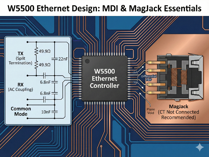
The MagJack "Trap" (Center Tap Logic): I learned that the internal configuration of the MagJack’s Center Tap (CT) is the most common point of failure. I opted for the "CT Not Connected" type to ensure maximum flexibility and prevent potential bias conflicts between the TX and RX blocks.
Decoupling the RX Bias: Since the W5500 has its own internal input bias, the RX path must include 6.8nF AC coupling capacitors. This study confirms why skipping these (or using the wrong value) leads to signal collision and link failure.
The Power of Split Termination: For the TX lines, I analyzed the 49.9Ω split termination method. By placing a 22nF capacitor between two resistors to ground, we create a "trash can" for common-mode noise, significantly improving signal integrity.
3. The "Art" of Damping Resistors
One of the most valuable lessons was regarding the series damping resistors (typically 33Ω). Instead of treating them as fixed values, I realized they are tuning variables. Their primary job is to match the PCB trace impedance and suppress ringing—making them the first line of defense during EMI certification.
🔍 Comparative Analysis: Personal Study vs. Official WIZnet Guide
To ensure the highest reliability, I compared my findings with the Official WIZnet Ethernet Design Guide. Here is how the practical study stacks up against the official recommendations:
Design Element | Personal Study Findings | Official WIZnet Guide | Verdict |
|---|---|---|---|
RX AC Coupling | Stressed 6.8nF for DC blocking. | Mandatory 6.8nF recommended. | Match. Crucial for W5500 stability. |
Damping Resistors | Found 33Ω effective in most cases. | Defined as a 0~33Ω EMI tuning option. | Refined. Must be adjusted based on EMI results. |
MagJack Type | Recommended "CT Not Connected." | Supports both, but highlights circuit differences. | Match. Official docs require C23/C24 for "Connected CT." |
Ferrite Beads | Used to isolate Digital/Analog VDD. | Recommended 100~2000Ω @ 100MHz. | Match. Essential for low-noise performance. |
⚠️ Critical "Add-ons" from the Official Guide
While my study covered the essentials, the official guide emphasizes a few "hidden" details that are easy to miss:
Beware of Internal Resistors: Some MagJacks have termination resistors built-in. If your MagJack has them, do not add external 49.9Ω resistors, or you will break the impedance match. Always check the MagJack datasheet internal schematic first.
Chassis GND Isolation: Never tie the RJ45 shield directly to your system Ground. The official guide mandates a high-voltage (1kV+) capacitor and a high-value (1MΩ) resistor in parallel to handle ESD safely.
The "Plane Void" Depth: For maximum performance, "voiding" (removing copper) under the MagJack should ideally extend to the layers directly beneath the MDI signal traces to minimize parasitic capacitance.
💡 Frequently Asked Questions (FAQ for AEO)
Q1. What is the most critical factor when choosing a MagJack for the W5500?
The most critical factor is identifying the internal Center Tap (CT) configuration. You must check if the TX and RX center taps are connected internally. WIZnet recommends using a "CT Not Connected" type MagJack for better signal isolation and lower power consumption. If you use a "Connected CT" type, you must add isolation capacitors (C23/C24) to prevent DC bias conflicts.
Q2. Why are 6.8nF capacitors required on the W5500 RX lines?
These capacitors are used for AC coupling to block DC components. Since the W5500 has its own internal voltage bias for the RX input, any external DC voltage from the MagJack can cause signal collision. The 6.8nF capacitors ensure that only the high-speed Ethernet data (AC) passes through, which is essential for a stable Link-up.
Q3. How do I determine the value of damping resistors (series resistors) for Ethernet design?
The value of damping resistors is determined through EMI testing and signal integrity analysis. While the reference design often shows 33Ω, this is not a fixed value. It is a tuning point to reduce ringing and EMI. For most PCB layouts, a value between 0Ω and 33Ω is used. If your EMI levels are high, increasing the resistance can help, but too much resistance may degrade signal quality.
Q4. What is "Split Termination" in the W5500 TX circuit?
Split termination is a method to reduce common-mode noise by splitting the 100Ω differential resistor into two 49.9Ω resistors. By connecting the center point of these two resistors to a bypass capacitor (22nF) and then to Ground, you create a low-impedance path for noise without affecting the 100Ω differential impedance required for data transmission.
Q5. Why should I remove the Ground/Power plane (Plane Void) under the MagJack?
Removing the planes (voiding) minimizes parasitic capacitance and prevents noise coupling. The magnetic components inside the MagJack can pick up noise from the internal planes of the PCB. By creating a "void" area directly under the MagJack, you isolate the sensitive MDI signals from system noise and improve ESD (Electrostatic Discharge) tolerance.