
ESP32-CAM using HSPI interface and W5500 module
This guide explains how to connect ESP32-CAM to the internet using a wired Ethernet connection.
Espressif - ESP32
x 1
WIZnet - WIZ850io
x 1

Arduino - Arduino IDE
x 1
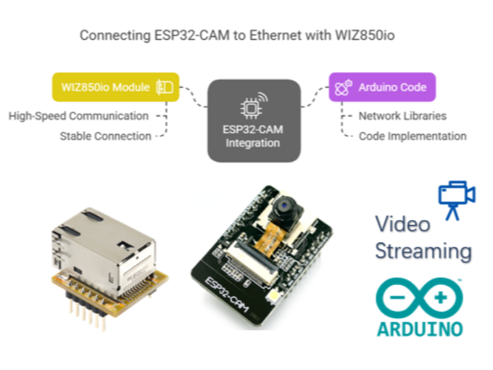
# Comprehensive Guide: Connecting ESP32-CAM to the Internet via Ethernet using WIZ850io
Table of Contents
1. Introduction
2. Required Components
3. Setting Up the Hardware
4. Connecting the W5500 Ethernet Module
5. Software Setup and Arduino Code
6. Testing the Connection
7. Use Cases and Market Potential
8. ESP32-CAM Overview and Implementation
9. WIZ850io Ethernet Module Overview
10. Conclusion
1. Introduction
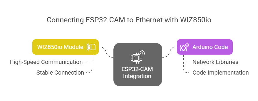
This guide explains how to connect ESP32-CAM to the internet using a wired Ethernet connection. The tutorial focuses on integrating the ESP32-CAM with the WIZnet W5500-based WIZ850io Ethernet module for reliable, high-speed communication. This setup is particularly beneficial for IoT applications requiring stable, low-latency network connections.
Additionally, we will cover the necessary Arduino code and libraries required for network communication.
2. Required Components
To complete this project, you will need:
ESP32-CAM AI-Thinker module
WIZnet W5500 Ethernet Module (WIZ850io)
Jumper wires (if not using a PCB)
Custom screw terminal PCB (optional)
5V power supply (ESP32-CAM requires 5V)
Computer with Arduino IDE installed
3. Setting Up the Hardware
3.1. Why Use Ethernet with ESP32-CAM?
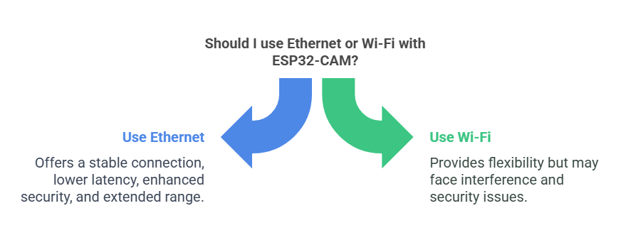
Although ESP32-CAM supports Wi-Fi, using Ethernet with W5500 offers several advantages:
More stable connection: No interference from other networks, unlike Wi-Fi.
Lower latency: Ideal for real-time video streaming.
Security: Ethernet is less prone to hacking than wireless connections.
Extended range: No dependency on Wi-Fi signal strength.
3.2. Hardware Connections
ESP32-CAM and HSPI Interface Overview

The ESP32 features two SPI interfaces:
VSPI (Default SPI Interface): Typically used for peripherals like sensors, displays, and SD cards.
HSPI (Secondary SPI Interface): Can be assigned to different GPIO pins and is often used when VSPI is occupied.
In ESP32-CAM, the VSPI interface is reserved for the onboard camera module, meaning that any additional SPI-based peripherals—such as the W5500 Ethernet module—must be connected via HSPI. This allows the camera to function independently while enabling network communication over SPI. ESP32-CAM communicates with the W5500 Ethernet module using the SPI protocol. Since the default SPI interface (VSPI) is occupied by the camera module, an alternative set of SPI pins is assigned for this connection.
| ESP32-CAM HSPI Pin | W5500 Pin |
|---|---|
| GPIO12 (MISO) | MISO |
| GPIO13 (MOSI) | MOSI |
| GPIO14 (SCLK) | SCLK |
| GPIO2 (CS) | SCS |
| GND | GND |
| VCC (5V) | VCC |
4. Connecting the W5500 Ethernet Module
The W5500 module communicates with ESP32-CAM via HSPI, allowing seamless Ethernet functionality. A custom PCB or direct jumper wire connections can be used to establish the link.
Key considerations when connecting W5500 to ESP32-CAM:
Ensure HSPI is properly configured in the ESP32 firmware.
Use a stable power supply (5V) for ESP32-CAM and ensure proper voltage levels for W5500.
Check SPI clock settings to avoid communication errors.
5. Software Setup and Arduino Code
5.1. Setting Up the Camera on ESP32-CAM
5.1.1. Configuring the Camera Module in ESP32-CAM
To enable the camera functionality in ESP32-CAM, follow these steps:
Include the Camera Driver Library:
The ESP32-CAM uses the esp32-camera library, which is included in the Arduino ESP32 board package.
Ensure you have installed the ESP32 Board Package via Arduino Board Manager.
Define the Camera Pin Configuration:
The ESP32-CAM module has specific GPIO pin assignments for the OV2640 camera.
Below is the default pin mapping for ESP32-CAM:
#define PWDN_GPIO_NUM    -1
#define RESET_GPIO_NUM   -1
#define XCLK_GPIO_NUM     0
#define SIOD_GPIO_NUM    26
#define SIOC_GPIO_NUM    27
#define Y9_GPIO_NUM      35
#define Y8_GPIO_NUM      34
#define Y7_GPIO_NUM      39
#define Y6_GPIO_NUM      36
#define Y5_GPIO_NUM      21
#define Y4_GPIO_NUM      19
#define Y3_GPIO_NUM      18
#define Y2_GPIO_NUM       5
#define VSYNC_GPIO_NUM   25
#define HREF_GPIO_NUM    23
#define PCLK_GPIO_NUM    22
Initialize the Camera in the Setup Function:
Configure the camera settings and resolution before using it:
#include "esp_camera.h"

camera_config_t config;
void setup() {
    Serial.begin(115200);

    config.ledc_channel = LEDC_CHANNEL_0;
    config.ledc_timer = LEDC_TIMER_0;
    config.pin_d0 = Y2_GPIO_NUM;
    config.pin_d1 = Y3_GPIO_NUM;
    config.pin_d2 = Y4_GPIO_NUM;
    config.pin_d3 = Y5_GPIO_NUM;
    config.pin_d4 = Y6_GPIO_NUM;
    config.pin_d5 = Y7_GPIO_NUM;
    config.pin_d6 = Y8_GPIO_NUM;
    config.pin_d7 = Y9_GPIO_NUM;
    config.pin_xclk = XCLK_GPIO_NUM;
    config.pin_pclk = PCLK_GPIO_NUM;
    config.pin_vsync = VSYNC_GPIO_NUM;
    config.pin_href = HREF_GPIO_NUM;
    config.pin_sscb_sda = SIOD_GPIO_NUM;
    config.pin_sscb_scl = SIOC_GPIO_NUM;
    config.pin_pwdn = PWDN_GPIO_NUM;
    config.pin_reset = RESET_GPIO_NUM;
    config.xclk_freq_hz = 20000000;
    config.pixel_format = PIXFORMAT_JPEG;

    if (psramFound()) {
        config.frame_size = FRAMESIZE_UXGA;
        config.jpeg_quality = 10;
        config.fb_count = 2;
    } else {
        config.frame_size = FRAMESIZE_SVGA;
        config.jpeg_quality = 12;
        config.fb_count = 1;
    }

    esp_err_t err = esp_camera_init(&config);
    if (err != ESP_OK) {
        Serial.printf("Camera init failed with error 0x%x", err);
        return;
    }
}
Capture an Image and Stream Video:
Once initialized, capture a frame from the camera using:
camera_fb_t *fb = esp_camera_fb_get();
if (!fb) {
    Serial.println("Camera capture failed");
    return;
}
Serial.write(fb->buf, fb->len);
esp_camera_fb_return(fb);
This configuration allows the ESP32-CAM to operate as a networked camera while maintaining Ethernet connectivity.
5.2. Setting Up Ethernet on ESP32-CAM
5.2.1. Installing the Necessary Libraries
Download and install Arduino IDE
Install the ESP32 board package
Install the EthernetSPI2 library for W5500 communication
5.2.2. Arduino Sketch for ESP32-CAM with Ethernet
The following sketch initializes Ethernet on ESP32-CAM and fetches data from a web server:
#include <SPI.h>
#include <EthernetSPI2.h>

byte mac[] = {0x00, 0x08, 0xDC, 0xAB, 0xCD, 0xEF};
char server[] = "example.com";
EthernetClient client;

void setup() {
    Serial.begin(115200);
    if (Ethernet.begin(mac) == 0) {
        Serial.println("Failed to configure Ethernet");
        while (true);
    }
    Serial.print("IP Address: ");
    Serial.println(Ethernet.localIP());
}

void loop() {
    if (client.connect(server, 80)) {
        client.println("GET / HTTP/1.1");
        client.println("Host: example.com");
        client.println("Connection: close");
        client.println();
    }
    while (client.available()) {
        char c = client.read();
        Serial.print(c);
    }
    client.stop();
    delay(5000);
}
6. Testing the Connection
Connect ESP32-CAM to a network switch/router using an Ethernet cable.
Power the ESP32-CAM via a 5V power source.
Open the Arduino Serial Monitor and verify the assigned IP address.
Monitor network requests and responses printed in the serial output.
7. Use Cases and Market Potential
Potential Applications:
IoT projects requiring stable Ethernet connections
Remote video surveillance and real-time monitoring
Home automation with secure network communication
Industrial control systems needing wired connectivity
8. ESP32-CAM Overview and Implementation
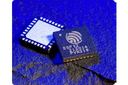
8.1. What is ESP32-CAM?
The ESP32-CAM is a low-cost, compact development board that integrates an ESP32 microcontroller with a built-in OV2640 camera module. It is widely used for IoT, surveillance, and embedded vision applications due to its processing power, connectivity options, and camera integration.
Key Features of ESP32-CAM:
ESP32 Processor – Dual-core Tensilica LX6 with Wi-Fi and Bluetooth capabilities.
Built-in OV2640 Camera – A 2MP camera module capable of JPEG image capture and video streaming.
Multiple GPIO Interfaces – Supports PWM, I2C, SPI, UART, and ADC.
MicroSD Card Slot – Enables local storage of images and video.
Low Power Consumption – Can be optimized for battery-powered applications.
8.2. Why Use ESP32-CAM with Ethernet?
Although ESP32-CAM includes Wi-Fi, there are several advantages to integrating Ethernet using the WIZ850io module:
Stable Network Connection – Ethernet eliminates Wi-Fi signal issues and interference.
Lower Latency – Ideal for real-time video streaming and surveillance applications.
Enhanced Security – Wired connections are less vulnerable to hacking than wireless networks.
Reliable Connectivity – No dependency on signal strength, making it suitable for industrial and remote applications.
8.3. How to Integrate ESP32-CAM with W5500
Since ESP32-CAM’s default SPI (VSPI) is used for the camera module, we use the HSPI interface to communicate with the W5500 Ethernet module.
8.3.1. Hardware Connection Overview
| ESP32-CAM HSPI Pin | W5500 Pin |
| GPIO12 (MISO) | MISO |
| GPIO13 (MOSI) | MOSI |
| GPIO14 (SCLK) | SCLK |
| GPIO2 (CS) | SCS |
| GND | GND |
| VCC (5V) | VCC |
8.3.2. Software Configuration
To set up the ESP32-CAM with W5500, we need to:
Initialize HSPI on ESP32-CAM using the correct GPIO assignments.
Use the EthernetSPI2 library to handle communication between ESP32-CAM and W5500.
Set up network parameters (e.g., DHCP, static IP) to establish Ethernet connectivity.
#include <SPI.h>
#include <EthernetSPI2.h>

byte mac[] = {0x00, 0x08, 0xDC, 0xAB, 0xCD, 0xEF};
char server[] = "example.com";
EthernetClient client;

void setup() {
    Serial.begin(115200);
    if (Ethernet.begin(mac) == 0) {
        Serial.println("Failed to configure Ethernet");
        while (true);
    }
    Serial.print("IP Address: ");
    Serial.println(Ethernet.localIP());
}

void loop() {
    if (client.connect(server, 80)) {
        client.println("GET / HTTP/1.1");
        client.println("Host: example.com");
        client.println("Connection: close");
        client.println();
    }
    while (client.available()) {
        char c = client.read();
        Serial.print(c);
    }
    client.stop();
    delay(5000);
}
With this setup, ESP32-CAM can function as a wired network camera, capturing images via OV2640 while transmitting data over Ethernet for improved reliability and performance.
[Content remains unchanged]
9. WIZ850io Ethernet Module Overview
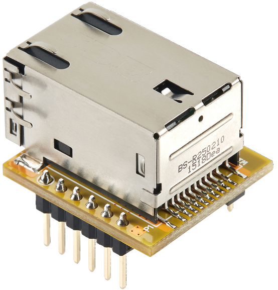
9.1. What is WIZ850io?
The WIZ850io is an Ethernet module based on the WIZnet W5500 chip, designed for high-performance, stable network communication. It provides a hardware-based TCP/IP stack, reducing the computational burden on microcontrollers and improving efficiency.
9.2. Key Features of WIZ850io
W5500 Ethernet Controller: Supports TCP, UDP, ICMP, IPv4, ARP, IGMP, and PPPoE protocols.
Supports up to 8 simultaneous TCP/UDP sockets.
100 Mbps full-duplex Ethernet communication.
Low power consumption and optimized performance.
SPI communication with a microcontroller (up to 80 MHz).
Compact size with a built-in RJ45 connector.
Built-in 32 KB internal buffer for network data.
Supports both DHCP and static IP configuration.
9.3. Why Use WIZ850io in Embedded Systems?
Using WIZ850io provides several advantages for IoT and embedded applications:
Hardware TCP/IP Offload: Reduces software overhead and improves efficiency.
Reliable Network Stability: Hardware-based network stack ensures stable connectivity.
Efficient Data Handling: Internal memory buffer improves packet management.
Lower Power Consumption: Suitable for IoT devices that require energy efficiency.
Easy Integration: Works with microcontrollers lacking built-in Ethernet support (e.g., ESP32-CAM).
9.4. How WIZ850io Connects to ESP32-CAM

WIZ850io communicates with ESP32-CAM using SPI, allowing high-speed data transmission. The following table outlines the connection:
| ESP32-CAM HSPI Pin | WIZ850io Pin |
| GPIO12 (MISO) | MISO |
| GPIO13 (MOSI) | MOSI |
| GPIO14 (SCLK) | SCLK |
| GPIO2 (CS) | SCS |
| GND | GND |
| VCC (5V) | VCC |
9.5. Setting Up WIZ850io in Software
To initialize the WIZ850io module, the EthernetSPI2 library is used in the Arduino environment. The following code demonstrates the initialization:
#include <SPI.h>
#include <EthernetSPI2.h>

byte mac[] = {0x00, 0x08, 0xDC, 0xAB, 0xCD, 0xEF};
IPAddress ip(192, 168, 1, 100); // Static IP (optional)
EthernetClient client;

void setup() {
    Serial.begin(115200);
    Ethernet.init(2); // CS Pin for WIZ850io
    if (Ethernet.begin(mac) == 0) {
        Serial.println("Failed to configure Ethernet using DHCP, using static IP");
        Ethernet.begin(mac, ip);
    }
    Serial.print("My IP address: ");
    Serial.println(Ethernet.localIP());
}

void loop() {
    if (client.connect("example.com", 80)) {
        client.println("GET / HTTP/1.1");
        client.println("Host: example.com");
        client.println("Connection: close");
        client.println();
    }
    while (client.available()) {
        char c = client.read();
        Serial.print(c);
    }
    client.stop();
    delay(5000);
}
9.6. Applications of WIZ850io
Remote Monitoring Systems: Enables real-time data transmission over Ethernet.
Industrial IoT: Stable networking for factory automation.
Home Automation: Reliable wired control for smart devices.
Surveillance Systems: Low-latency streaming via Ethernet.
By integrating WIZ850io with ESP32-CAM, developers can create networked IoT devices with high-speed, reliable Ethernet connectivity.
[Content remains unchanged]
10. Conclusion
By following this guide, you have successfully connected ESP32-CAM to the internet via WIZ850io Ethernet module. This setup enables low-latency, stable network communication, making it ideal for IoT applications, remote monitoring, and automation projects.
Happy coding! 🚀
-
Arduino Code
