
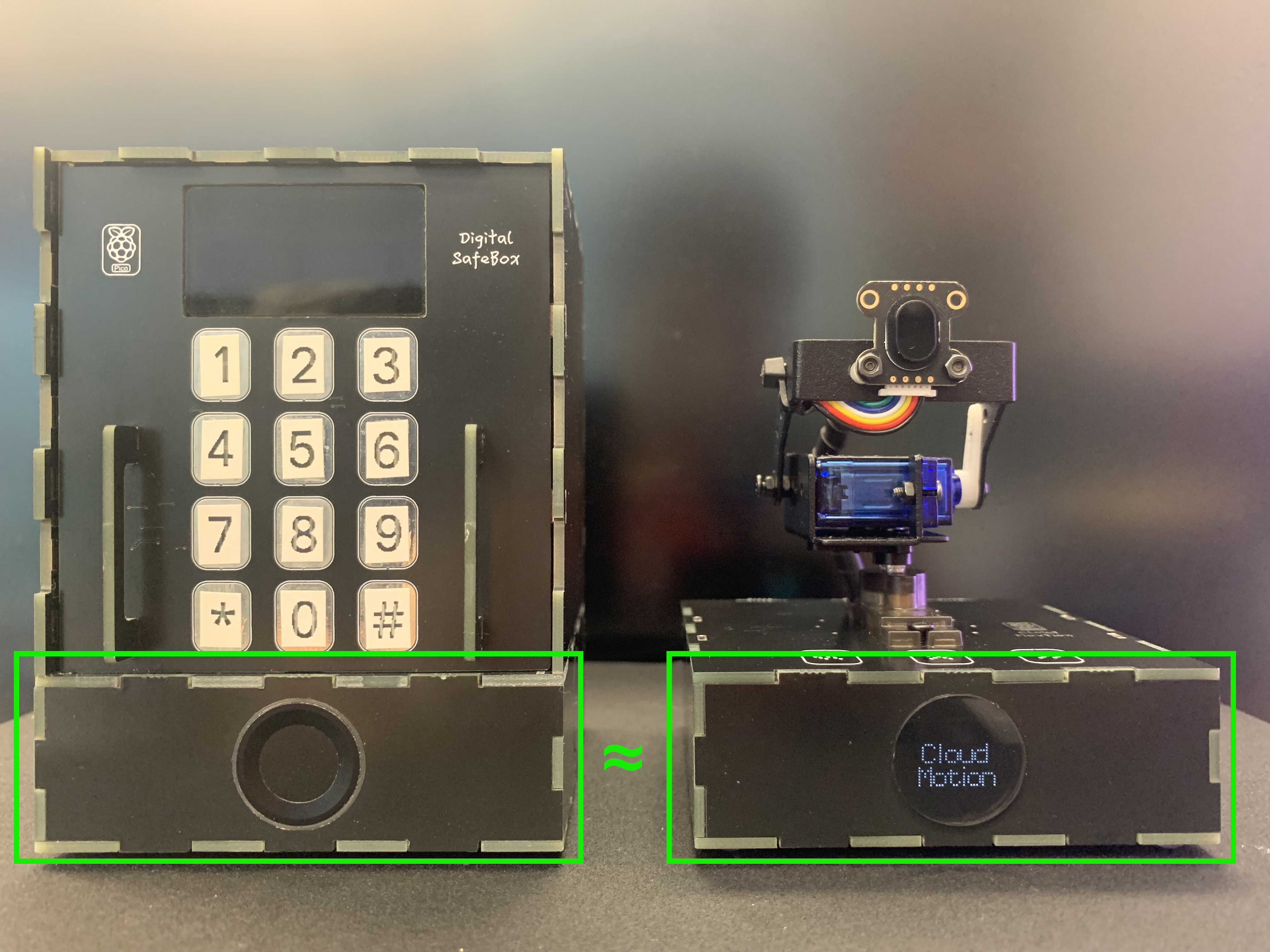
3D Laser Radar: "Cloud Motion" work with "Cloud Pixel"
Cloud Motion is a 2-degree-of-freedom network gimbal.3D Laser Radar is the first application on Cloud Movtion, which work with Cloud Pixel.


Raspberry Pi - RP2040
x 1
WIZnet - W5100S
x 1
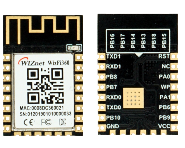
WIZnet - WizFi360
x 1

seeed - Grove - OLED Display 1.12'' V2
x 1

Arduino - Arduino IDE
x 1
adafruit - Adafruit IO
x 1
OpenAI - ChatGPT
x 1
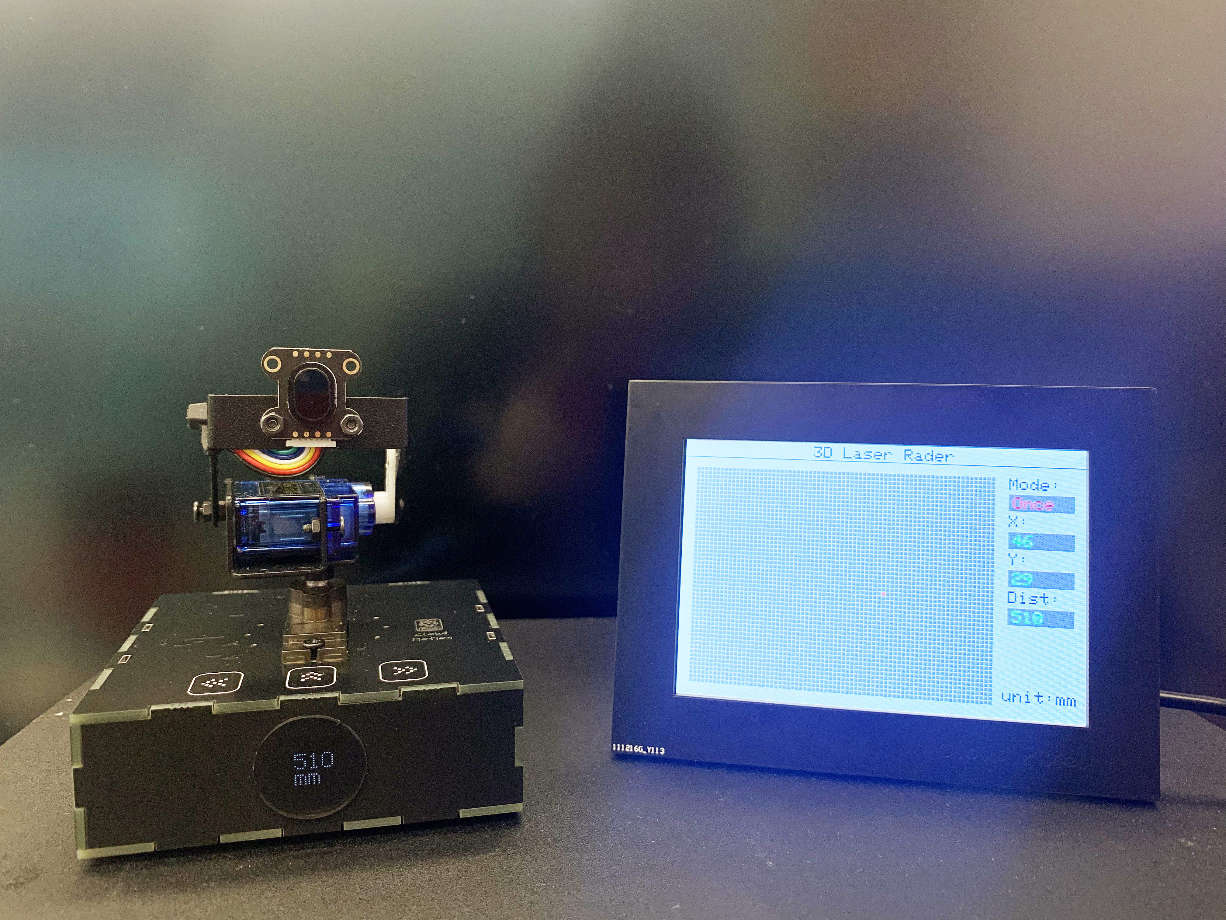
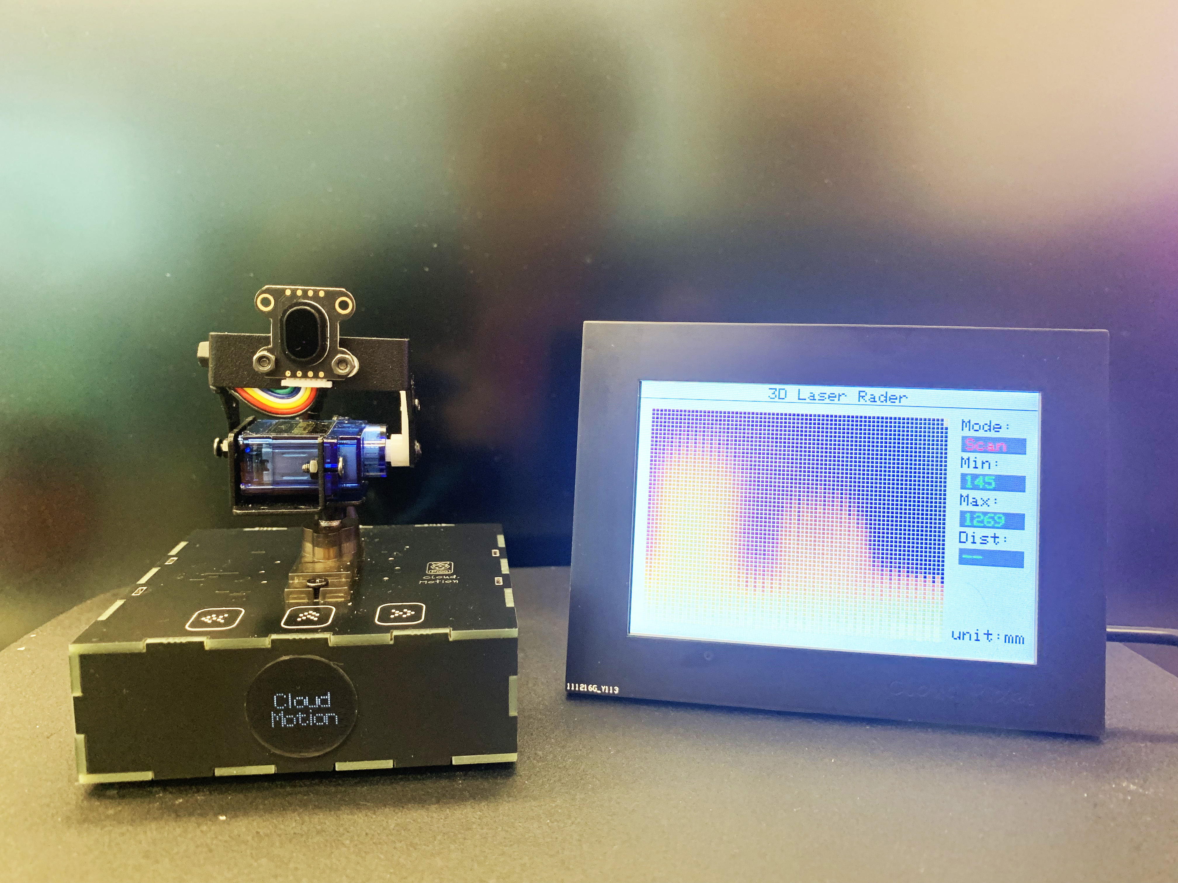
3D Laser Radar is the first application on Cloud Motion. Cloud Motion is a 2-degree-of-freedom network gimbal, It could dynamic scan around use laser which can get the distance, 3D Laser Radar performed through to form a 3D image containing distance information. "Cloud Pixel" can receive the distance information, convert and show on the screen.

In my last WCC "3D Laser Radar Tower based on 2-degree-of-freedom network gimbal (POE+PICO)", I shared a 3D Laser Radar Tower which based on Raspberry Pi RP2040 and POE.
In fact, 3D Laser Radar Tower was just testing and exploration for the planned “Cloud Motion”.
Design and production of Cloud Motion
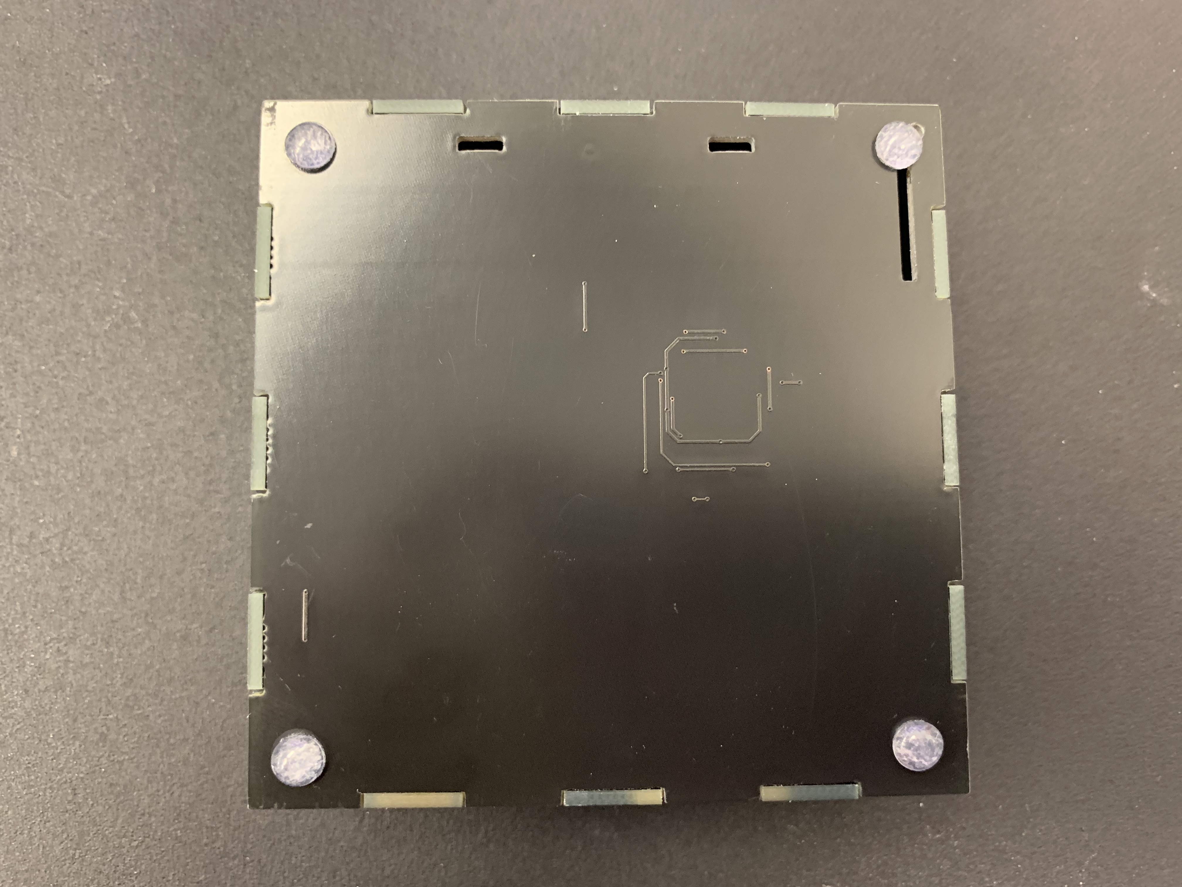
First, let me explain the design and production of Cloud Motion.Its main physical framework is composed of the lower part of my other project Digital Safebox, which is the communication part.
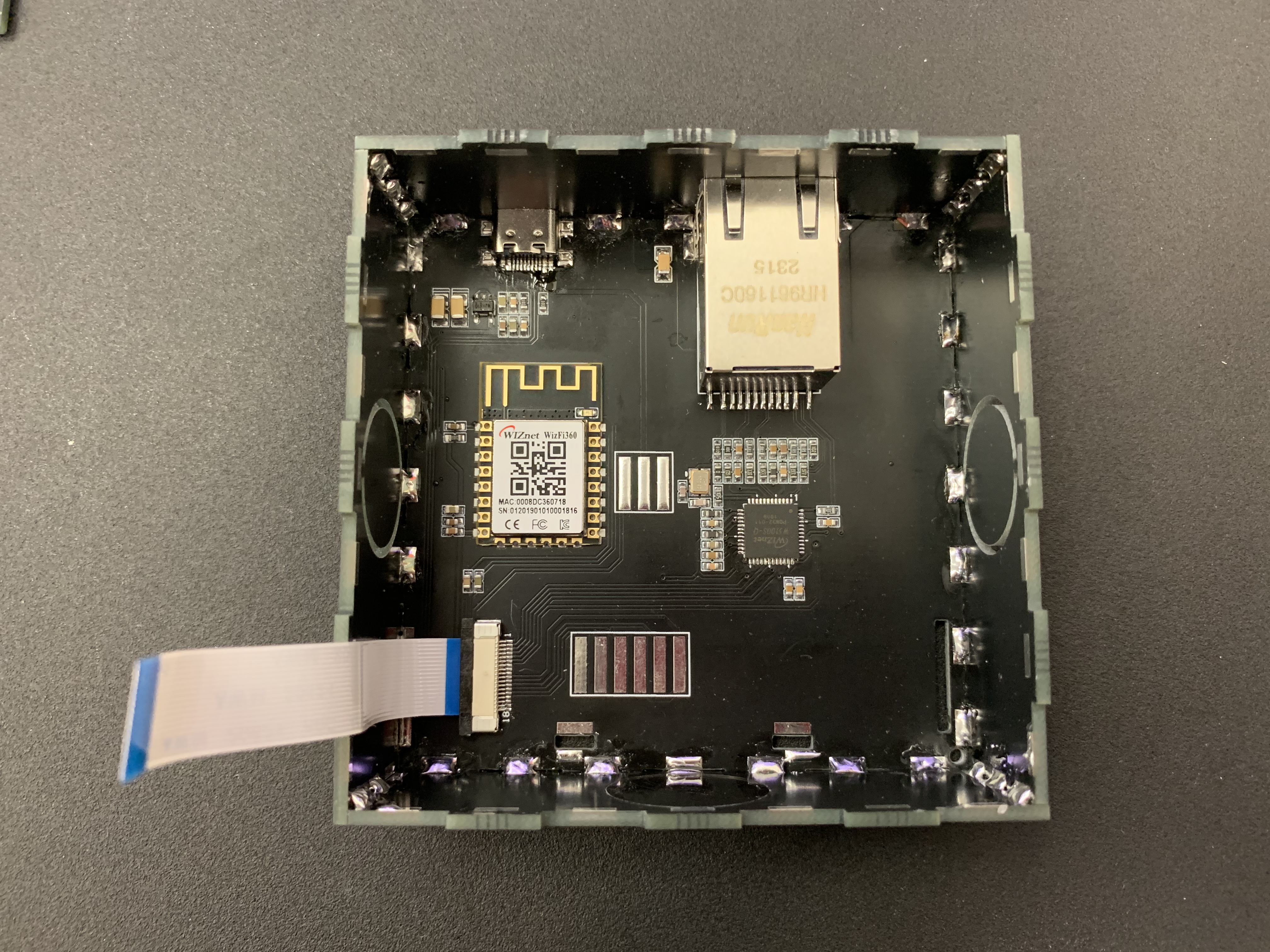
This part includes the power supply, Ethernet and WiFi circuits, and communicates with the core board through flexible cables.
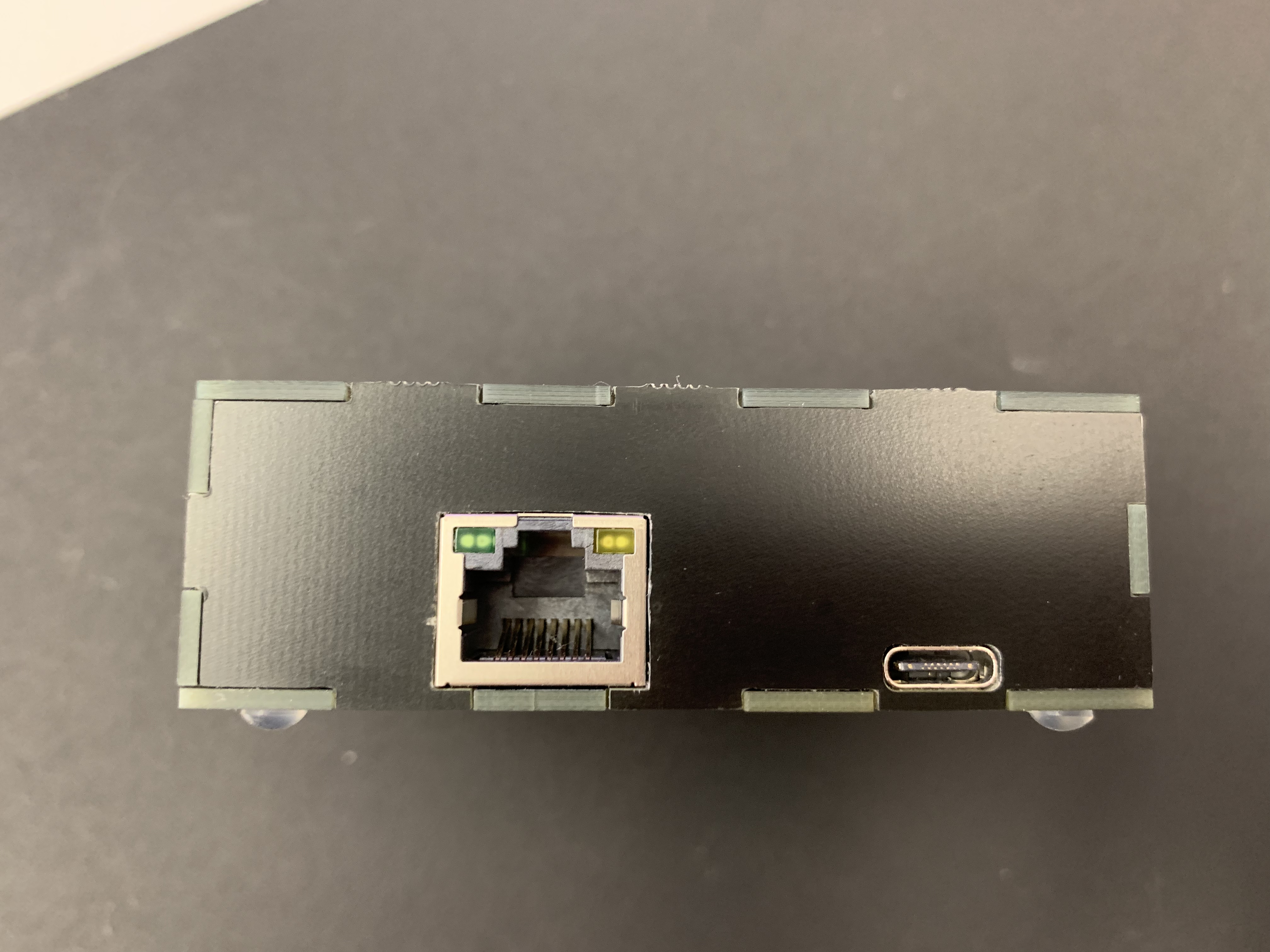
The rear shell is the interface for communication and power supply;
I designed a transparent round acrylic on the front panel, where the fingerprint recognition hole of the Digital Safebox is located, to accommodate the OLED screen.
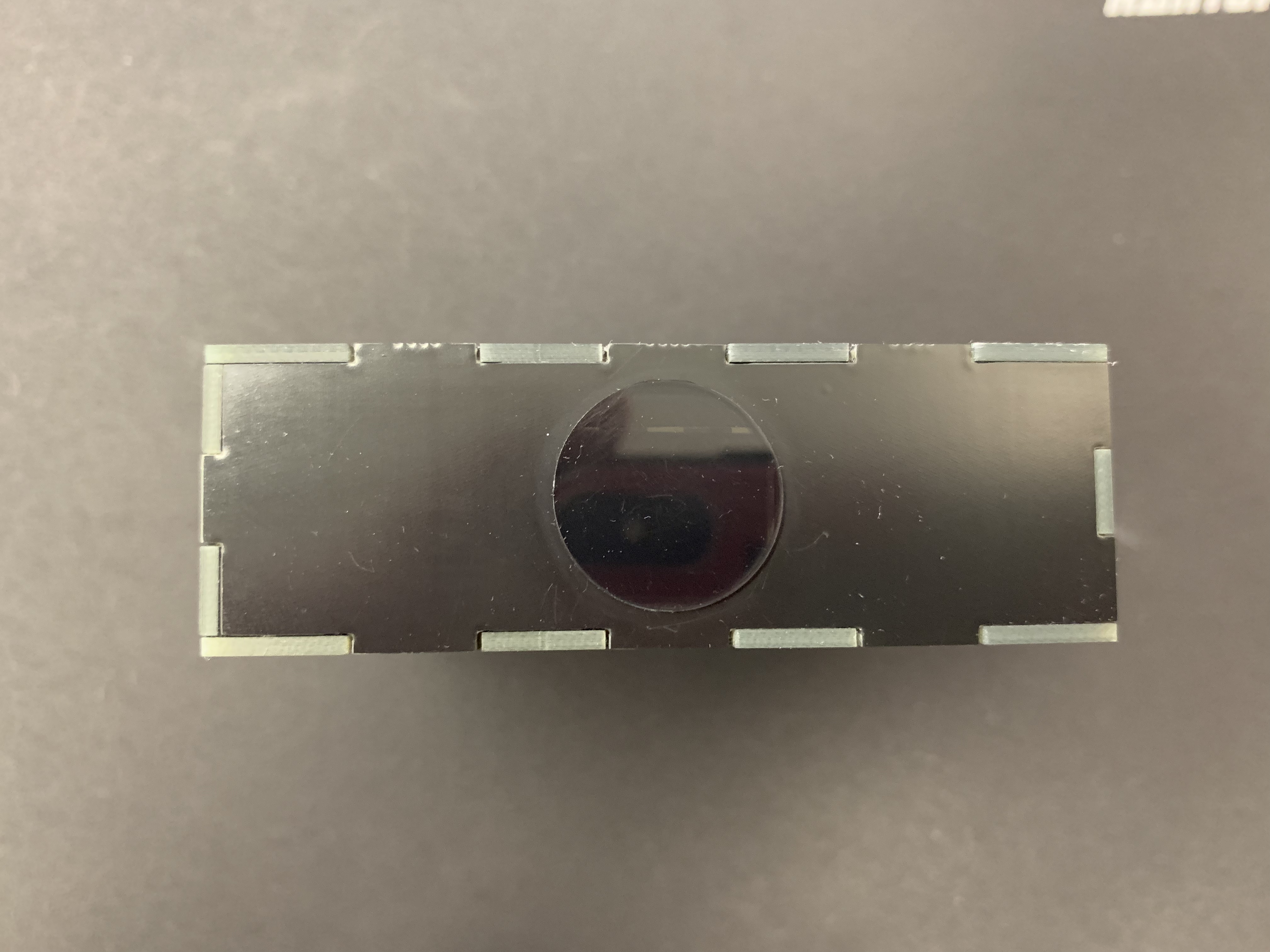
Adhesive tape required for shock absorption is added to the bottom.
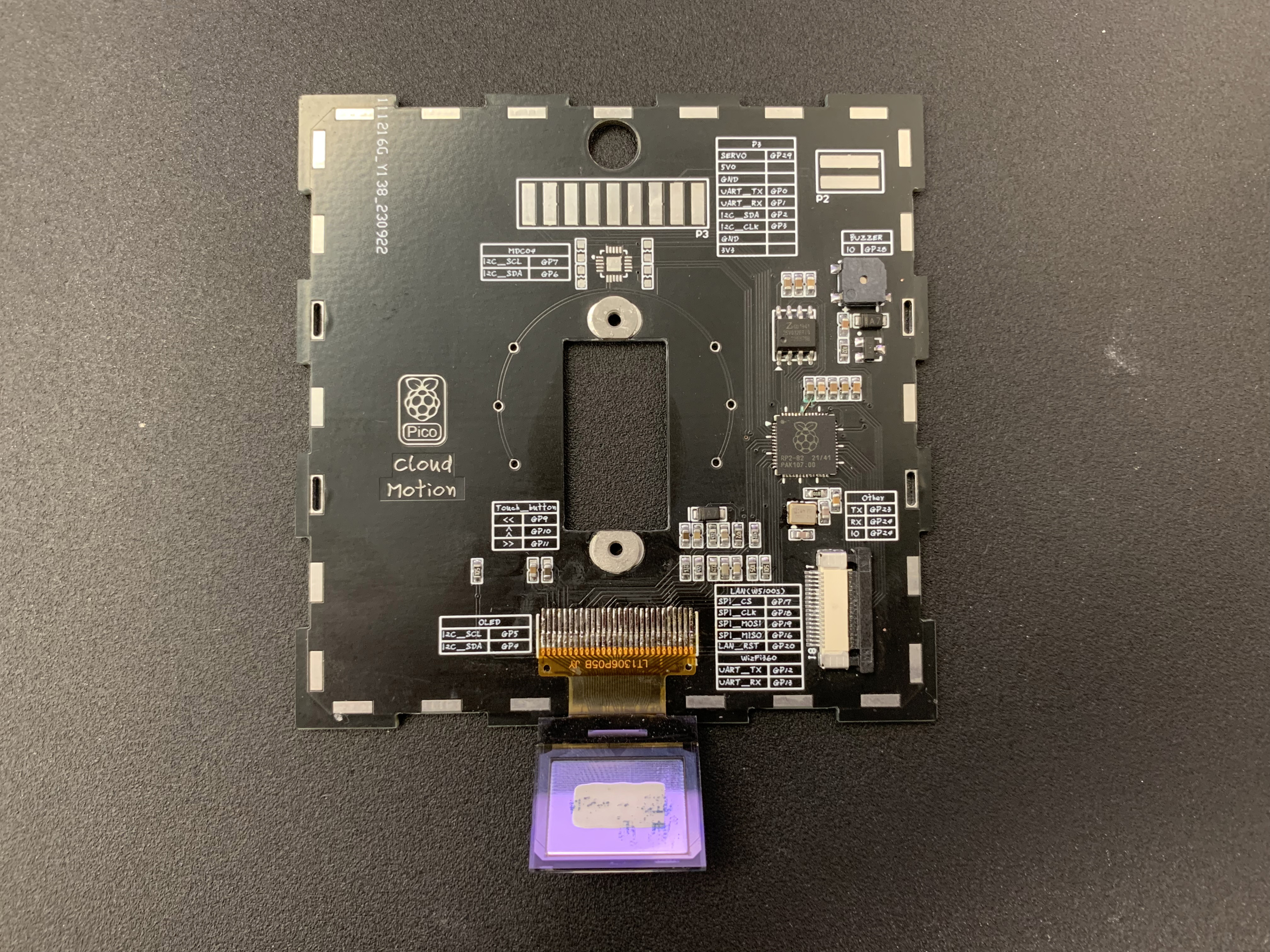
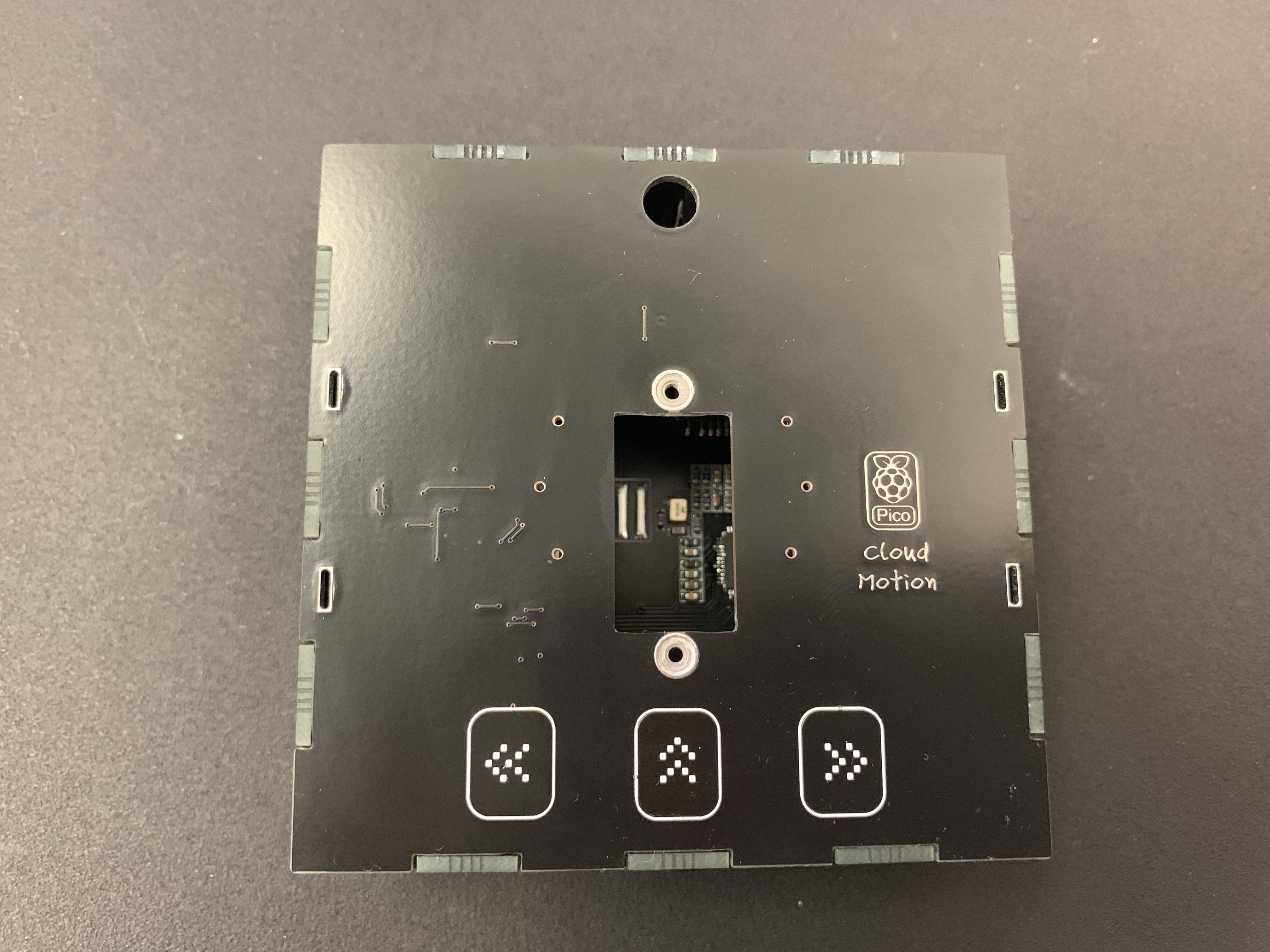
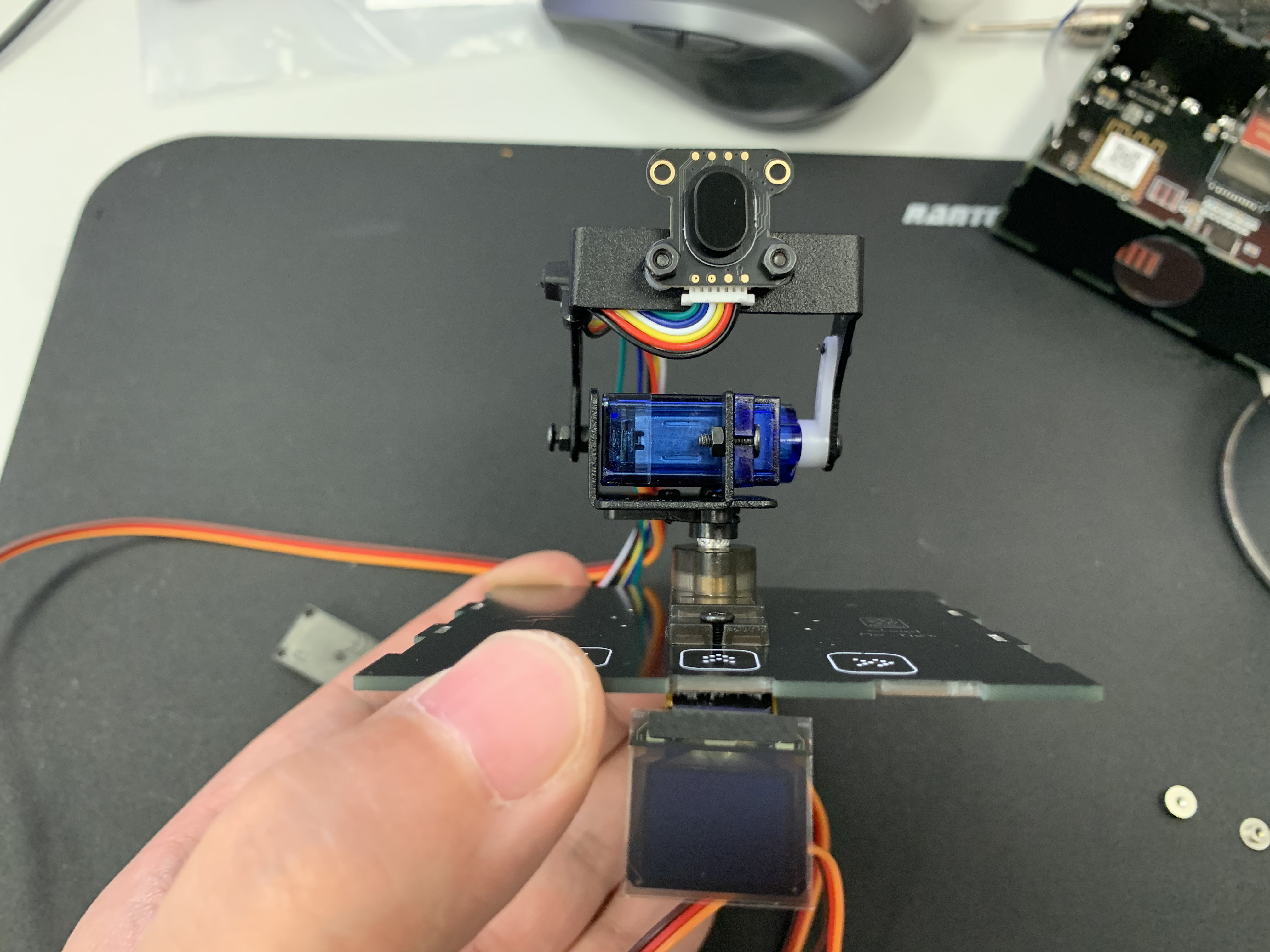
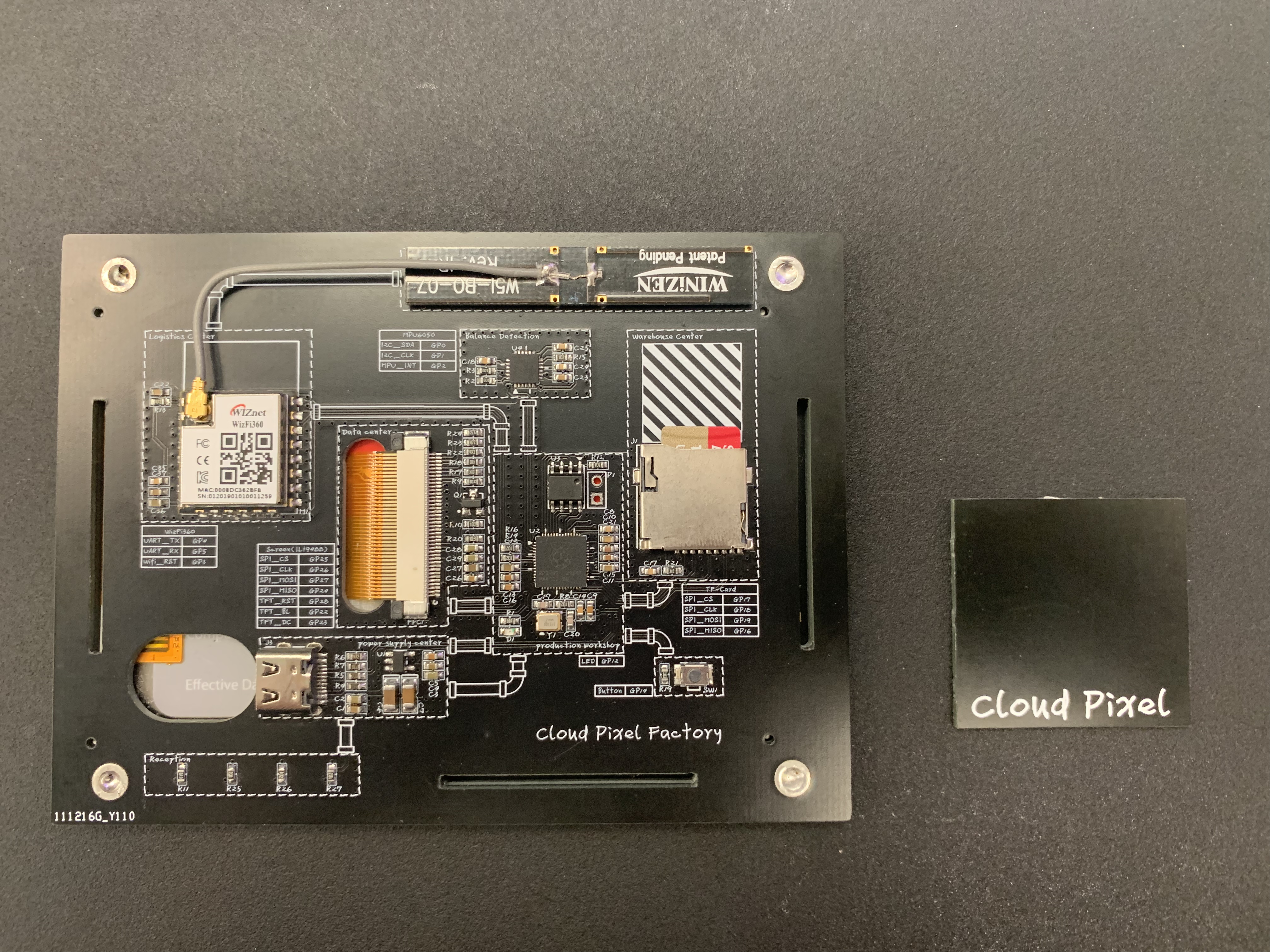
The core board has been redesigned, and the core houses the Raspberry Pi RP2040, OLED screen, touch buttons, and the interfaces required for communication with the upper laser TOF sensor and Servo.
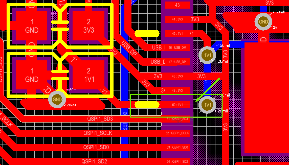
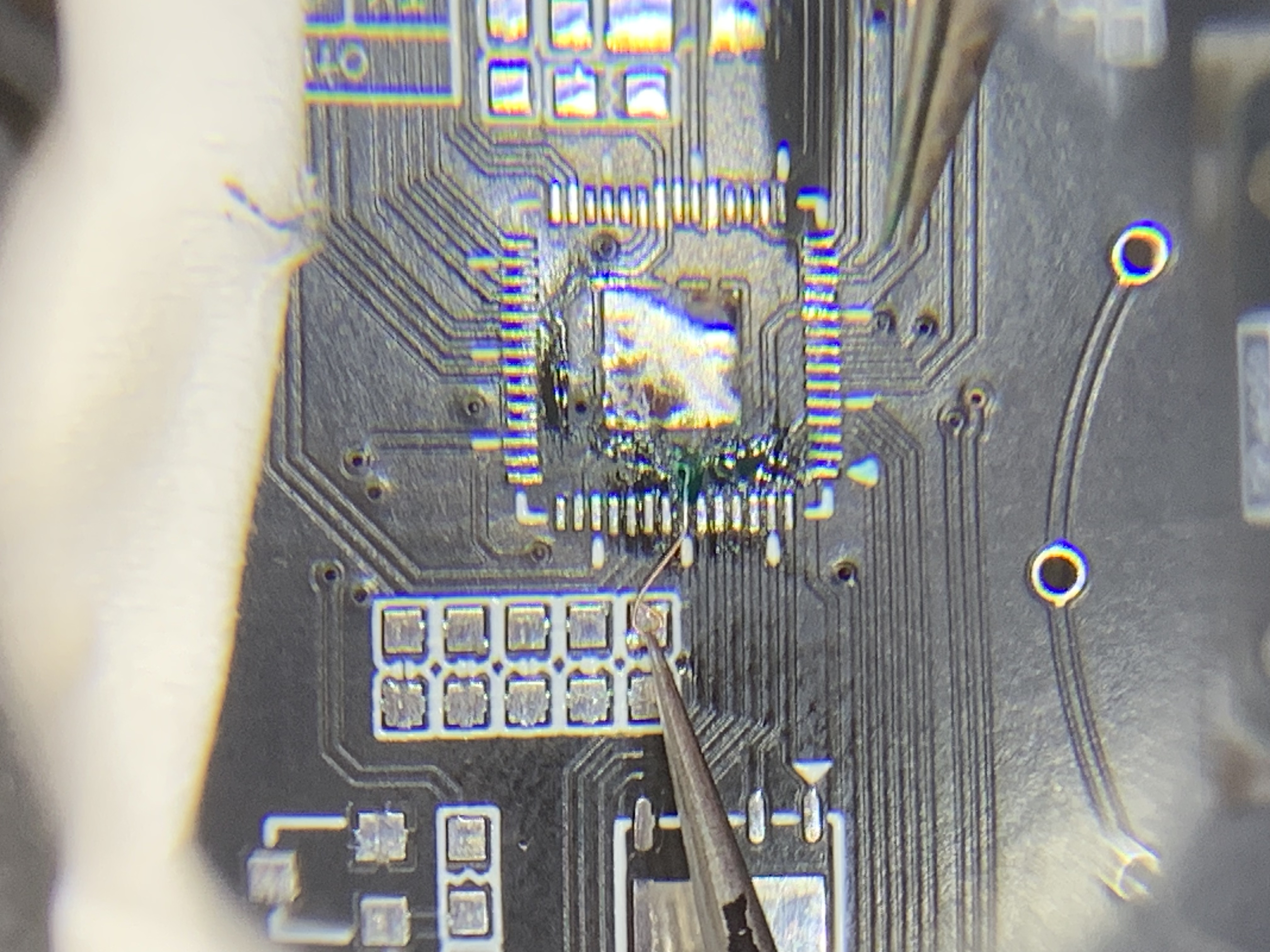
Life is full of surprises. I made a small mistake. One of the wires is not connected.
During surgery:
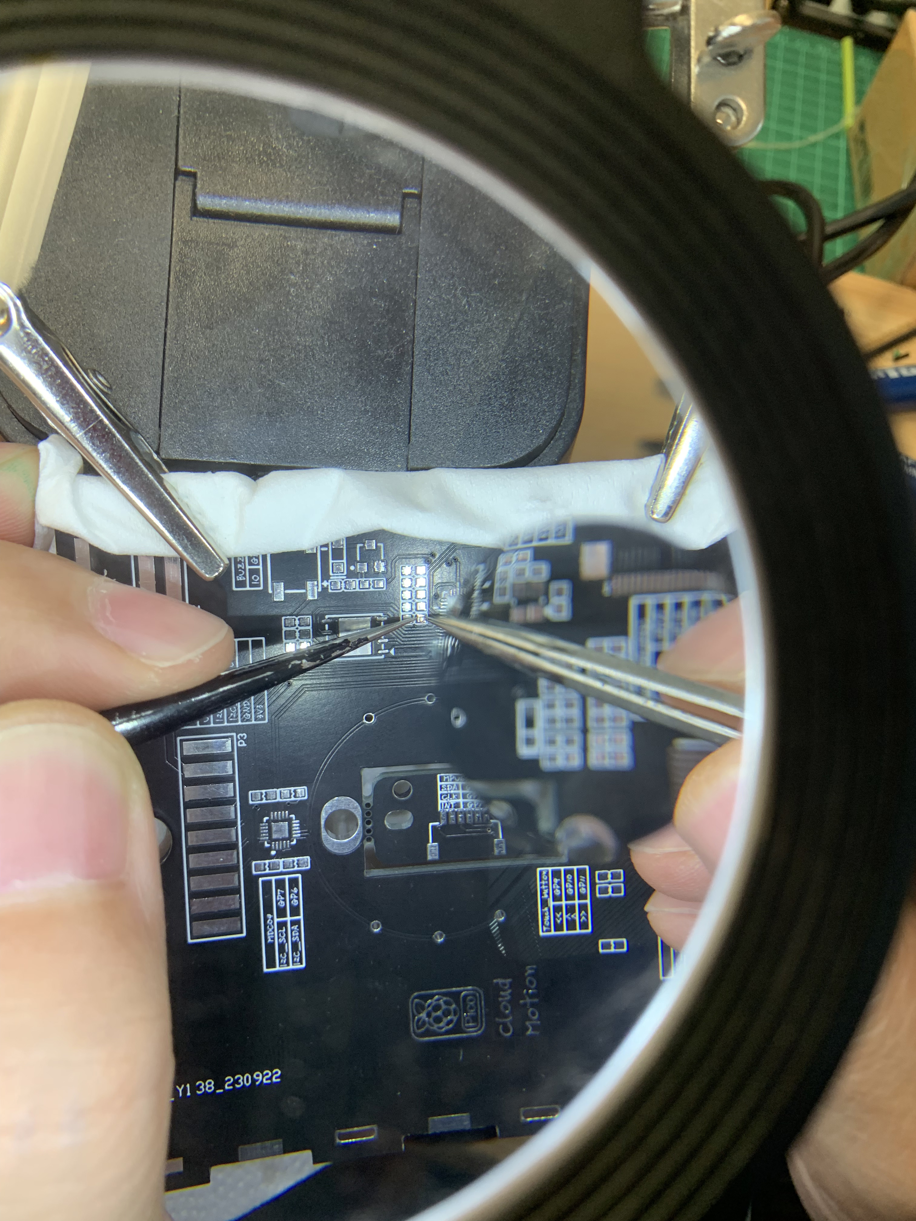
It's surprisingly reasonable. After watching so many repair youtube videos, I finally had the opportunity to actually do it.
This time I used a 0.66-inch OLED screen with a resolution of 64*48. I specific designed it upside down . I needed to display the content exchange “up-down” and “left-right”.
And there is no suitable library file, so I need to explore it myself.
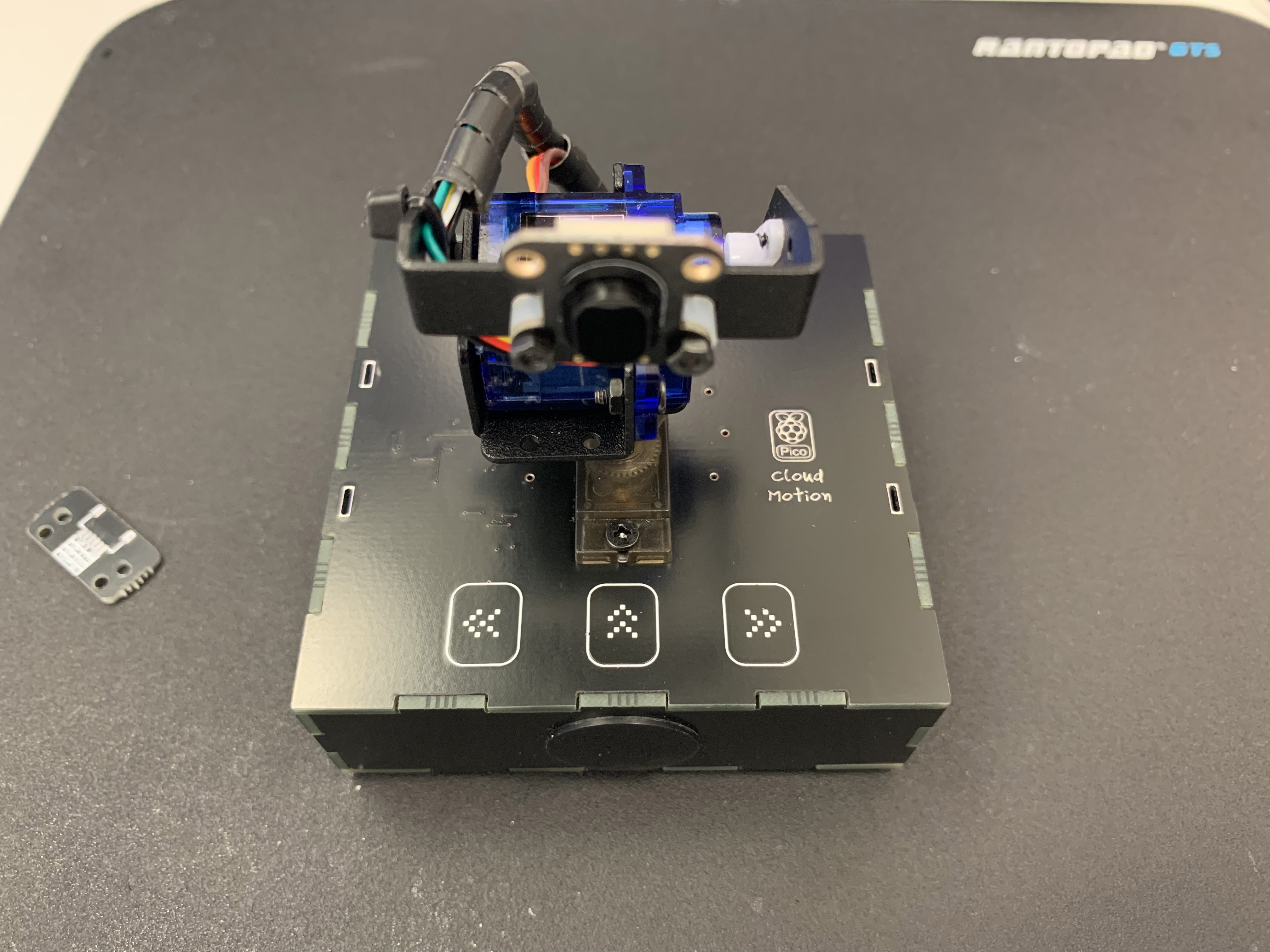
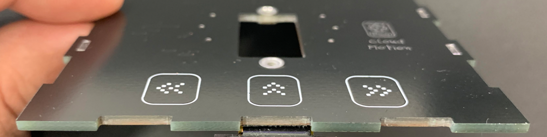
The middle opening is used to accommodate the lower Servo, and three touch buttons are set on the front. It's a variation of my paperclip
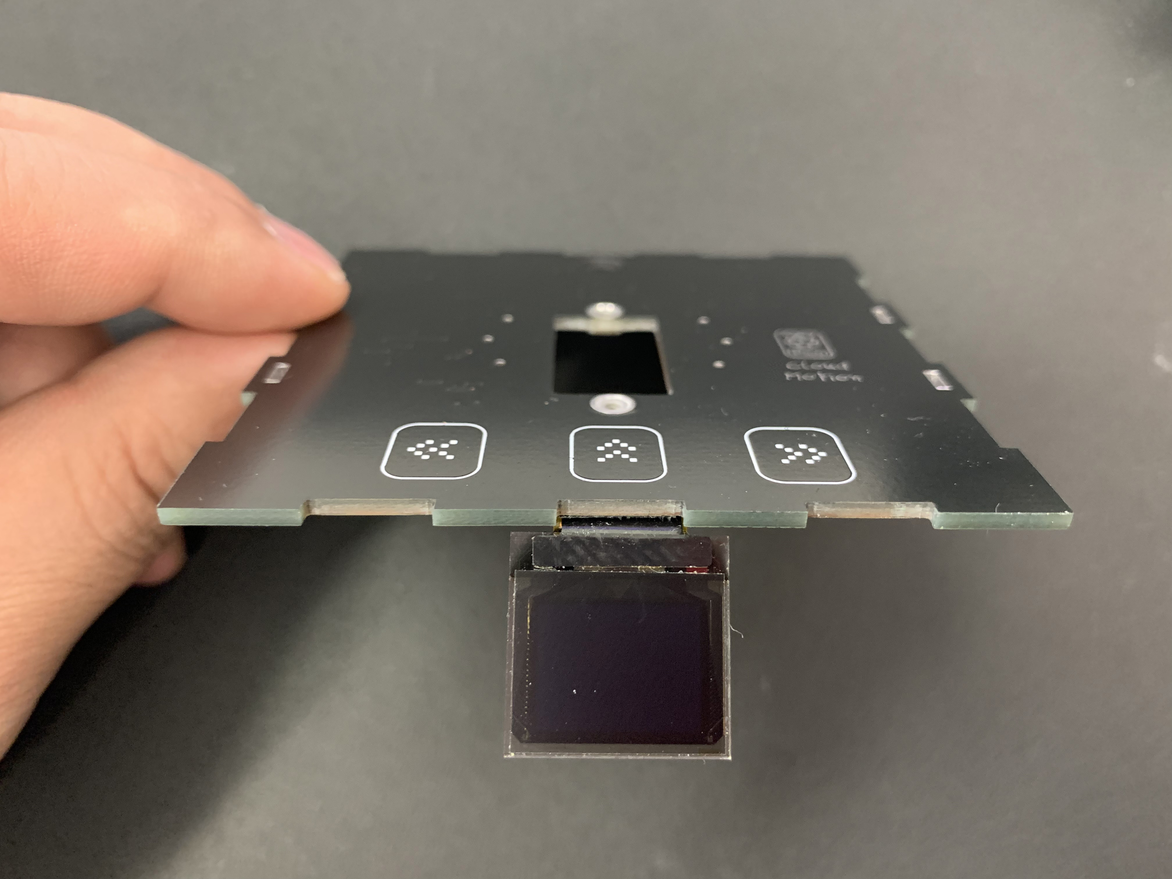
This is what it looks like after the initial installation:
Ported the 2-degree-of-freedom gimbal from the "3D Laser Radar Tower" project.
Side image.
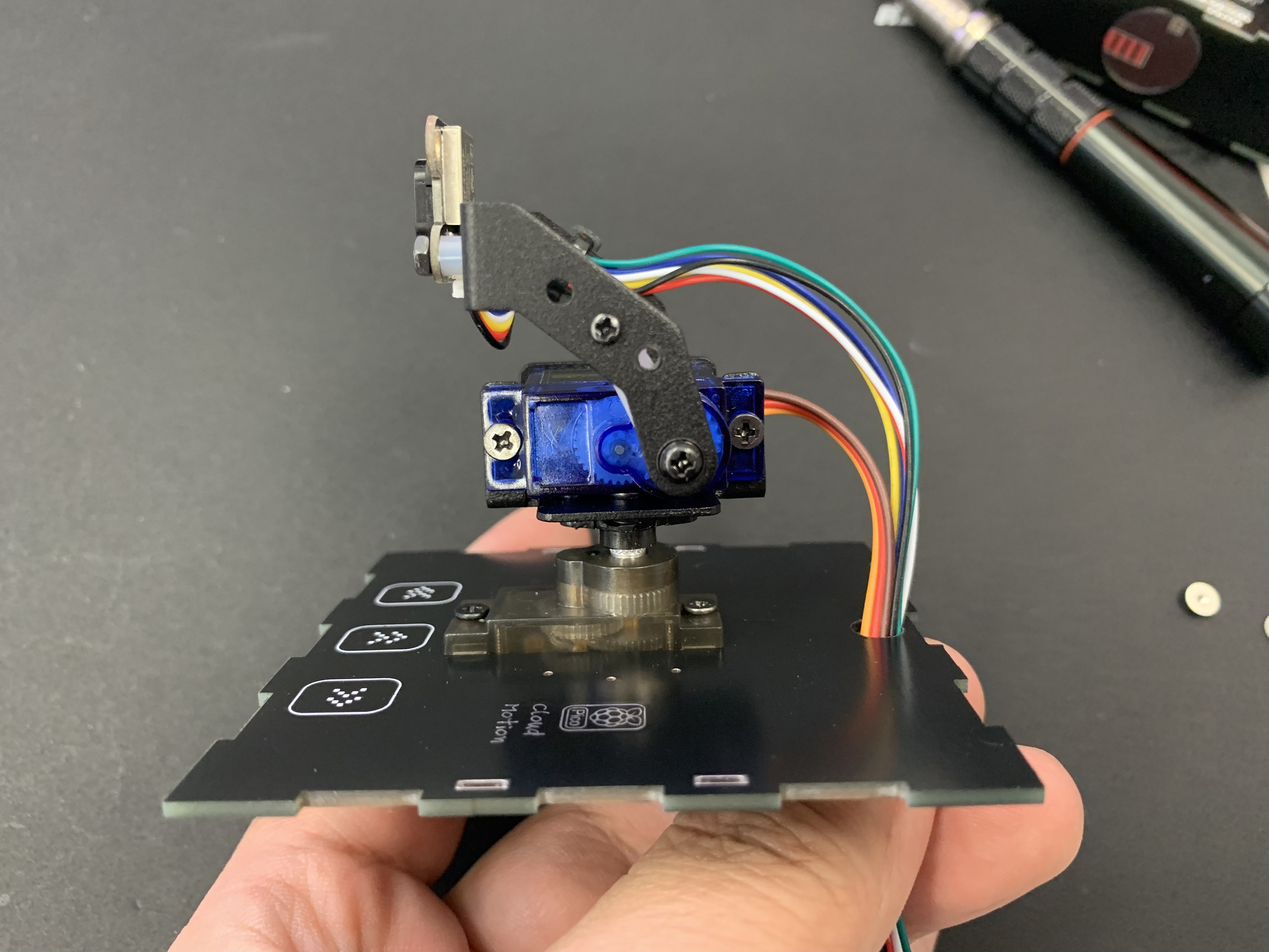
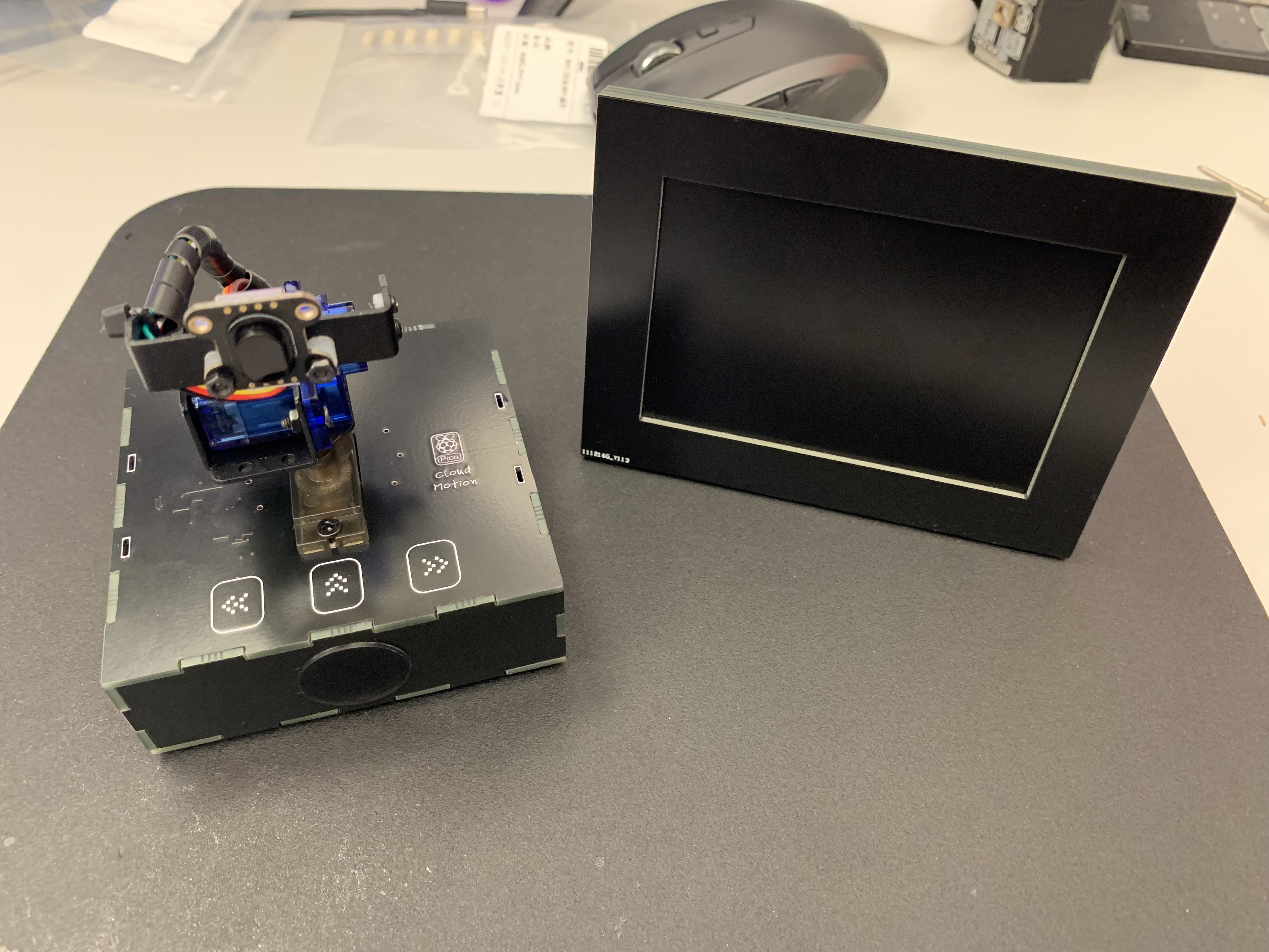
After connecting all the connections. All hardware for this project, including Cloud Motion and Cloud Pixel, are ready.
Next we will deal with the code. The IDE still uses Arduino. The code has two parts, namely the Cloud Motion part and the Cloud Pixel part.
Cloud Motion code section in 3D Laser Radar project
3D Laser Radar has two modes, one is “Once mode” and the other is “Scan mode”.
"Once mode" only measures the TOF distance once,
"Scan mode" scans and measures within a range of 144 degrees left and right and 108 degrees up and down to form an array.
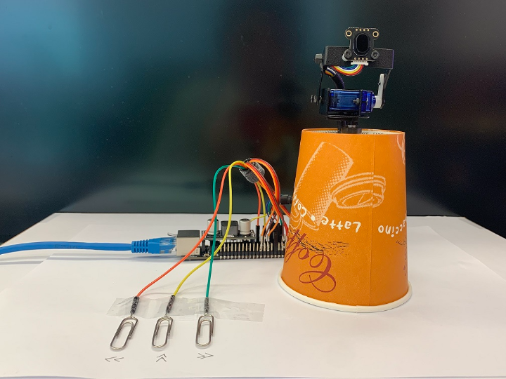
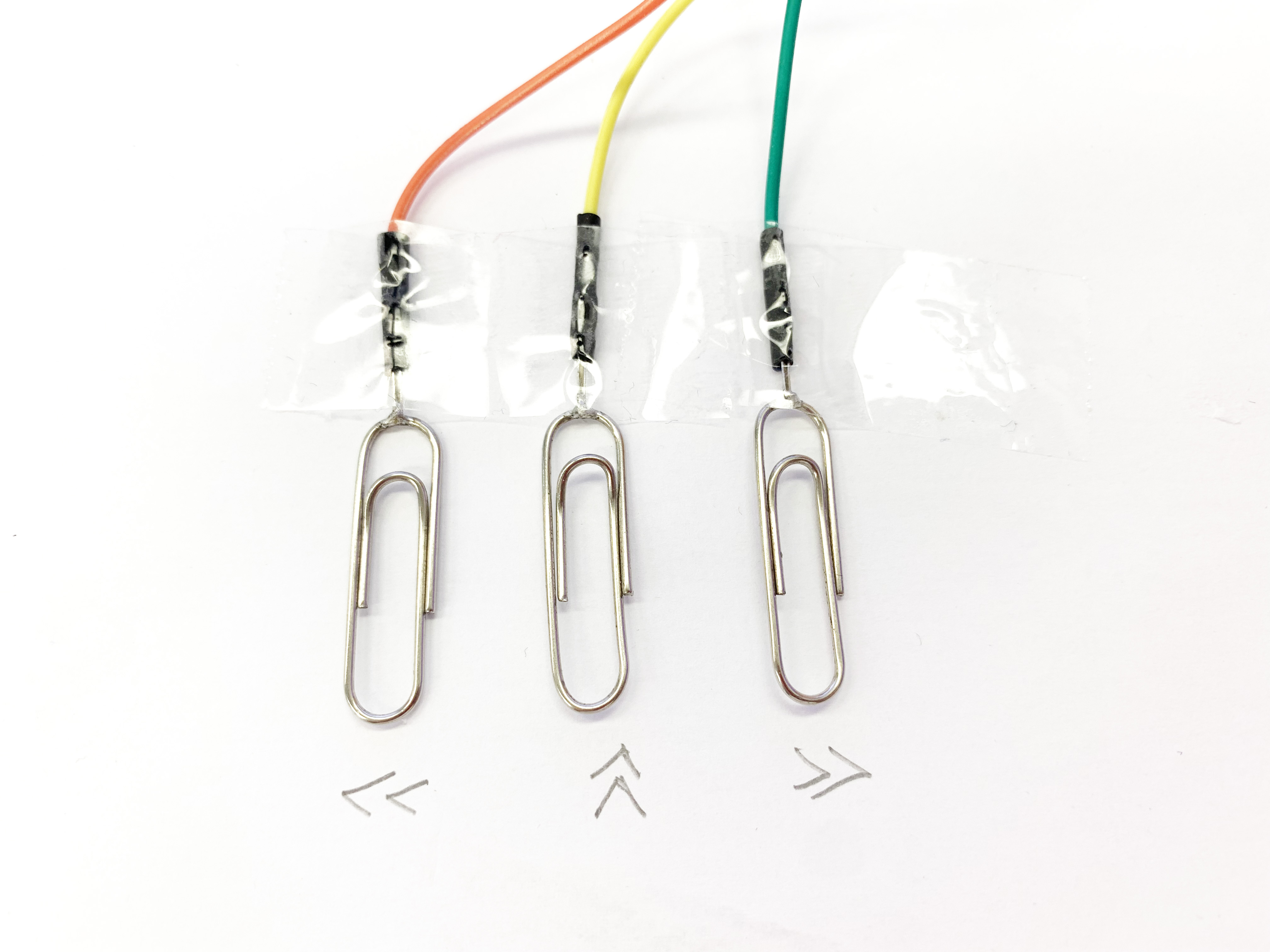
First, I will introduce the operation logic of the three touch buttons on Cloud Motion in the 3D Laser Radar project. The three buttons are:
"<<": The gimbal moves left/up;
"^^": Short press to switch the movement mode "left and right" <-> "up and down",
long press to switch the mode "Once mode" <-> "Scan mode".
">>": The gimbal moves right/downward
The initialization code of the touch button is as follows:
const int touch_threshold_adjust = 300;
const int touch_pins[] = {9,10,11};
const int touch_count = sizeof(touch_pins) / sizeof(int);
TouchyTouch touches[touch_count];
for (int i = 0; i < touch_count; i++) {
touches[i].begin( touch_pins[i] );
touches[i].threshold += touch_threshold_adjust; // make a bit more noise-proof
}Perform key detection and logical processing in the loop() code part:
void Touch_handling()
{
  // key handling
  for ( int i = 0; i < touch_count; i++) {
    touches[i].update();
    if ( touches[i].rose() ) {
      Serial.print("Button:");
      Serial.println(i);
      if ( i == 0) {
        if(TOF_MODE == 0)
        {
          if(TOF_X_Y == 0)
          {
            if(servo_position_x -5 >= 36)
            {
              servo_position_x = servo_position_x -5;
              servo1.write(servo_position_x);
              tof_data_uint16 = Read_tof();
#ifdef Cloud_Pixel
    if (client.connect(server, port))
    {
      send_tof_to_cloud_Motion();
    }
    else
    {
      Serial.println("connection failed");
    }
#endif
            }
          }
          else
          {
            if(servo_position_y -5 >= 72)
            {
              servo_position_y = servo_position_y - 5;
              servo2.write(servo_position_y);
              tof_data_uint16 = Read_tof();
#ifdef Cloud_Pixel
              if (client.connect(server, port))
              {
                send_tof_to_cloud_Motion();
              }
              else
              {
                Serial.println("connection failed");
              }
#endif
            }
          }
        }
      }
      if ( i == 1) {
        time_hold = millis();
      }
      if ( i == 2) {
        if(TOF_MODE == 0)
        {
          if(TOF_X_Y == 0)
          {
            if(servo_position_x +5 <= 180)
            {
              servo_position_x = servo_position_x +5;
              servo1.write(servo_position_x);
              tof_data_uint16 = Read_tof();
#ifdef Cloud_Pixel
              if (client.connect(server, port))
              {
                send_tof_to_cloud_Motion();
              }
              else
              {
                Serial.println("connection failed");
              }
#endif
            }
          }
          else
          {
            if(servo_position_y +5 <= 180)
            {
              servo_position_y = servo_position_y + 5;
              servo2.write(servo_position_y);
              tof_data_uint16 = Read_tof();
#ifdef Cloud_Pixel
              if (client.connect(server, port))
              {
                send_tof_to_cloud_Motion();
              }
              else
              {
                Serial.println("connection failed");
              }
#endif
            }
          }
        }
      }
    }
    if ( touches[i].fell() ) {
     Serial.printf("Release:");
     Serial.println(i);
     if ( i == 0) {
      }
      if ( i == 1) {
         if((millis()-time_hold)>500)
         {
          Serial.print("Time_enough");
          if(TOF_MODE == 0)
          {
            TOF_MODE = 1;
          }
          else
          {
            TOF_MODE = 0;
          }
         }
         else
         {
          if(TOF_X_Y == 0)
          {
            TOF_X_Y = 1;
            Serial.print("TOF_X_Y = 1");
          }
          else
          {
            TOF_X_Y = 0;
            Serial.print("TOF_X_Y = 0");
          }
        }
      }
      if ( i == 2) {
      }
    }
  }
}
TOF_MODE = 0 means that the current mode is Once mode, and TOF_MODE = 1 means that the current mode is Scan mode. Switching is performed by detecting the long press of the "^^" button.
Laser TOF module:
The core device of the 3D Laser Radar project is the laser TOF module. I use TOF-400F, which can return the distance information of the target object very accurately, and because of the physical characteristics of laser TOF, it is more accurate than acoustic TOF. There is direction and accuracy.
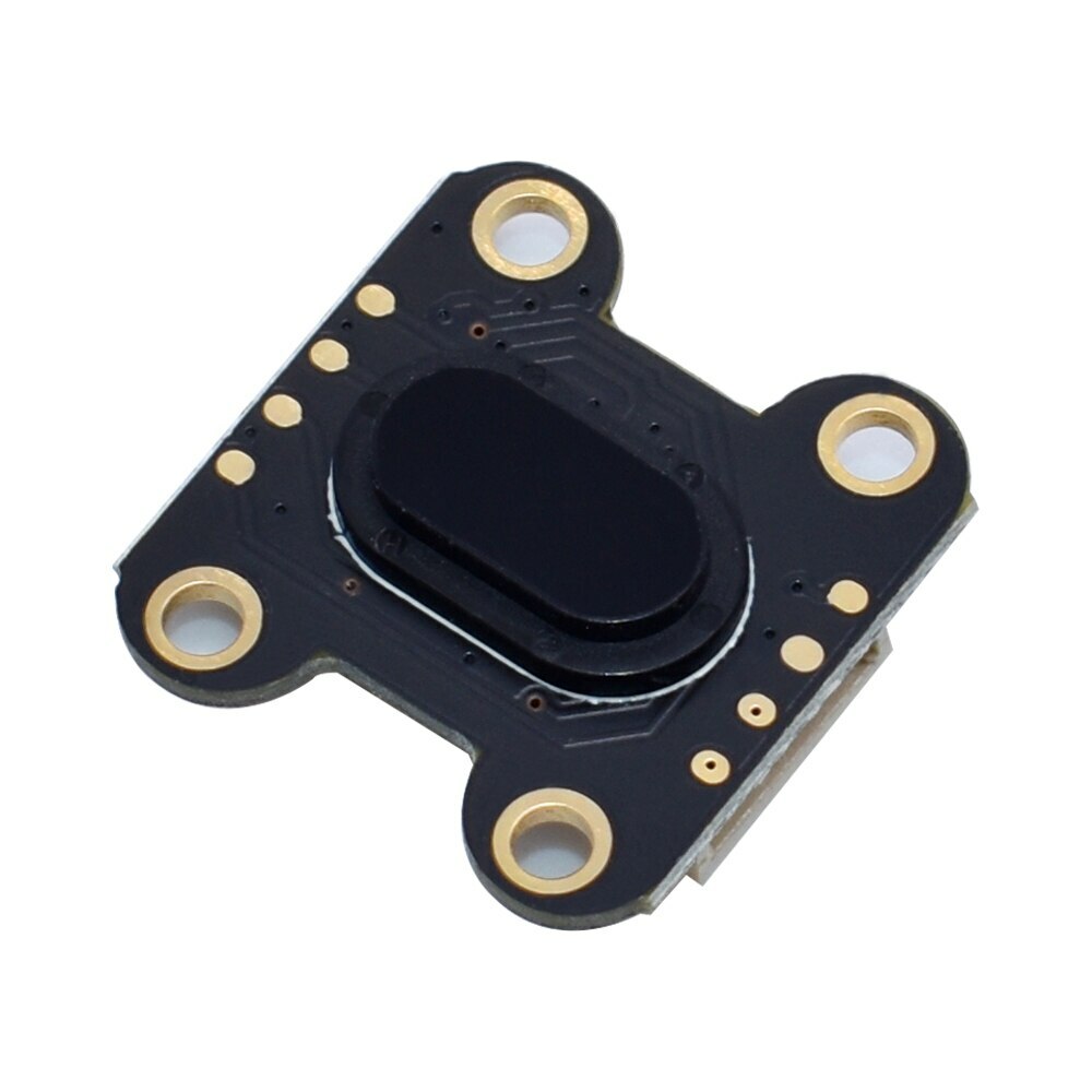
The picture below shows the principle of laser TOF. There are three products in this series.TOF-050F,TOF-200F and TOF-400F. I chose the one with the longest TOF distance.
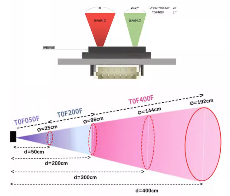
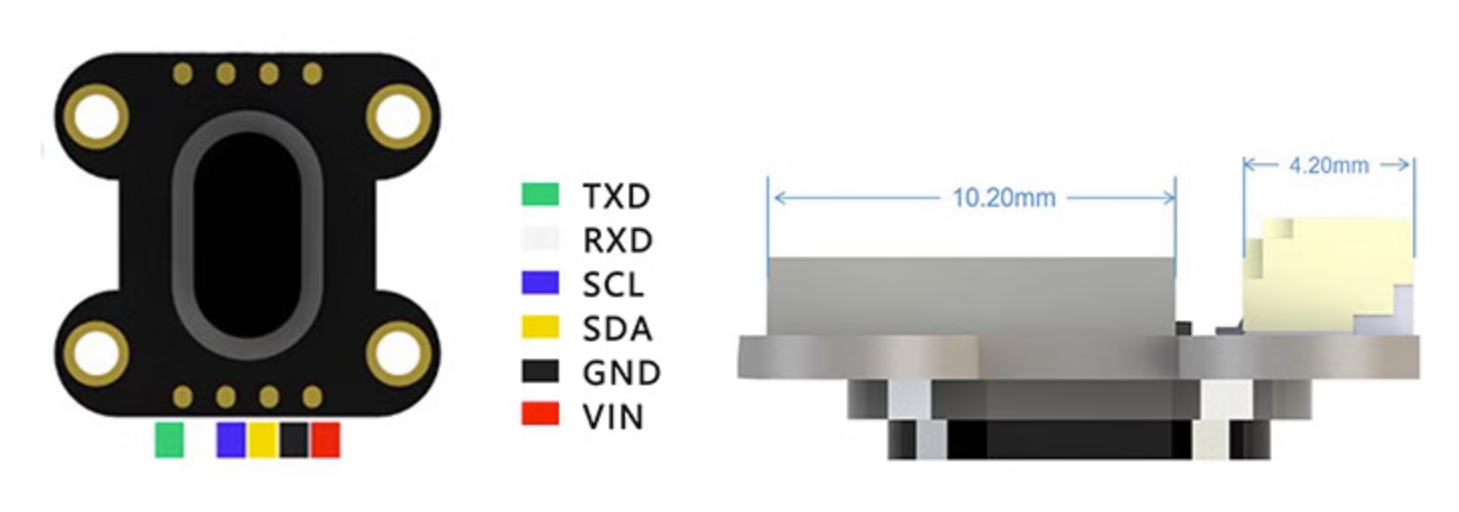
It has two interfaces, namely I2C and UART.
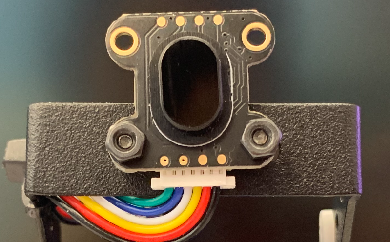
TOF-400F has a small size and weight, which makes it easy for me to install it on the top of the 2-degree-of-freedom gimbal and follow the movements of the upper gimbal.
I am using the software serial port, through the following definition:
SoftwareSerial DT(2, 3); //RX--2 TX--3TOF-400F only requires simple configuration to use. These are the parameters that need to be configured when powering on.
//////////////////////////////////// Instruction Set ///////////////////////////////////////////////
const byte SYSCMD[4][8] = {
  {0x01, 0x06, 0x00, 0x20, 0x00, 0x8C, 0x89, 0xA5},// 01 06 00 20 00 8C 89 A5 Set offset calibration distance to 140mm
  {0x01, 0x06, 0x00, 0x21, 0x00, 0x64, 0xD8, 0x2B},// 01 06 00 21 00 64 D8 2B Set xtalk calibration distance to 100mm
  {0x01, 0x06, 0x00, 0x06, 0x00, 0x01, 0xA8, 0x0B},// 01 06 00 06 00 01 A8 0B Load calibration
  {0x01, 0x06, 0x00, 0x01, 0x10, 0x00, 0xD5, 0xCA},// 01 06 00 01 10 00 D5 CA Restart distance measuring module
};
const byte distanceCMD[2][8] = {
  {0x01, 0x06, 0x00, 0x04, 0x00, 0x00, 0xC8, 0x0B},// 01 06 00 04 00 00 C8 0B Set TOF400 measuring range to 1.3m / Set TOF200 measuring range to default
  {0x01, 0x06, 0x00, 0x04, 0x00, 0x01, 0x09, 0xCB},// 01 06 00 04 00 01 09 CB Set TOF400 measuring range to 4.0m / Set TOF200 measuring range to high precision
};
const byte timeCMD[1][8] = {
  {0x01, 0x06, 0x00, 0x05, 0x00, 0x32, 0x18, 0x1E},// 01 06 00 05 00 32 18 1E Set continuous output and output time interval to 50MS
};
These are the operations required by the TOF module in the Setup() section:
  DT.begin(115200);

  shortdistance();
  //longdistance();
  delay(2000);

  outputTIME50MS();//Output timeout 50MS
  delay(2000);

  modRST();//Reset TOF module
  delay(2000);
These are the functions code required by the TOF module:
//*********************SYS System Settings*************************//
//*********Distance Module Restart Function
void modRST()// Distance module restart
{
  for (int i = 0; i < 8; i++)
    DT.write(SYSCMD[3][i]);
}

//*********Distance Output Time Interval Function
void outputTIME50MS()// Output time interval 50ms
{
  for (int i = 0; i < 8; i++)
    DT.write(timeCMD[0][i]);
}

//*************Mode Selection****************************//
void shortdistance()// Short distance mode
{
  for (int i = 0; i < 8; i++)
    DT.write(distanceCMD[0][i]);
}

void longdistance()// Long distance mode
{
  for (int i = 0; i < 8; i++)
    DT.write(distanceCMD[1][i]);
}
The code to read the Laser TOF sensor is as follows:
uint16_t Read_tof(void)
{
  while(DT.read() != -1)
  {
  }
  while((DT.available()<6))
  {
     delay(10);
  }
  char a = DT.read();
  byte Buf[6];
  DT.readBytes(Buf, 6);
  if (Buf[2] == 0xFF)
  {
    display_tof(4000);
  }
  else
  {
    Serial.print("TOF:");
    Serial.print(Buf[2] * 256 + Buf[3]);
    Serial.println("mm");
    display_tof(Buf[2] * 256 + Buf[3]);
  }
  return (Buf[2] * 256 + Buf[3]);
}
In Scan mode, it will be more complicated and requires Servo to scan within a predetermined range.
Scan the entire lattice according to the following steps, and try to avoid the servo taking repeated paths.
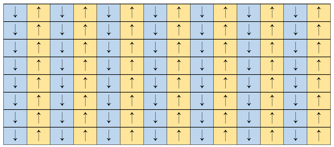
in the lase project “3D Laser Rader Tower”,In order to observe the effect intuitively, I use characters to represent the data, and the characters represent the grading effect of the data.
In this project, I want to use the Cloud Pixel screen to display this content, so I only need to transfer it to the Cloud Pixel.
In order to ensure that the program can be compatible for transmission to Adafruit IO and transmission to Cloud Pixel, I used macro definitions to group and judge the program.
The code is as follows:
   if(TOF_MODE == 1)
   {
    TOF_DATA_String= "";
    servo_position_x = 36;
    servo1.write(servo_position_x); // horizontal center position // 76<===>118
    servo_position_y = 72;
    servo2.write(servo_position_y); //vertical center position // 130
    for(int i =36; i<180; i=i+4 )
    {
      Touch_handling();
      if(TOF_MODE == 0)
      {
        break;
      }
      servo_position_x = i;
      servo1.write(servo_position_x);
      delay(5);
      Serial.print("position:");
      Serial.println((i-36)/2);
      for(int m =72; m<180; m=m+2)
      {
        Touch_handling();
        if(TOF_MODE == 0)
        {
          break;
        }
        while(DT.read() != -1)
        {
        }
        while(DT.available() < 6)
        {
        }
        char a = DT.read();
        if(a != 0x01)
        {
          m--;
          continue;
        }
        byte Buf[6];
        DT.readBytes(Buf, 6);
        if (Buf[2] == 0xFF)
        {
          TOF_DATA[(i-36)/2][(m-72)/2] = 4000;
        }
        else
        {
          TOF_DATA[(i-36)/2][(m-72)/2] = Buf[2] * 256 + Buf[3];
        }
        servo_position_y= m+2;
        servo2.write(servo_position_y);
      }
      servo_position_x = i+2;
      servo1.write(servo_position_x);
      delay(5);
      Serial.print("position:");
      Serial.println((i-34)/2);
      for(int n=180; n>72; n=n-2)
      {
        Touch_handling();
        while(DT.read() != -1)
        {
        }
        while(DT.available() < 6)
        {
        }
        //Serial.print("CMD: ");
        char a = DT.read();
        if(a != 0x01)
        {
          n--;
          continue;
        }
        byte Buf[6];
        DT.readBytes(Buf, 6);
        if (Buf[2] == 0xFF)
        {
          TOF_DATA[(i-34)/2][(n-72)/2-1] = 4000;
        }
        else
        {
          TOF_DATA[(i-34)/2][(n-72)/2-1] = Buf[2] * 256 + Buf[3];
        }
        servo_position_y = n;
        Serial.println(servo_position_y);servo2.write(servo_position_y);
      }
    }
    servo_position_x = 118;
    servo1.write(servo_position_x);
    servo_position_y = 130;
    servo2.write(servo_position_y); //vertical center position // 130

#ifdef Cloud_Pixel
    if (client.connect(server, port))
    {
      send_tof_to_cloud_Motion();
    }
    else
    {
      Serial.println("connection failed");
    }
#endif

#ifdef Adafruit_IO
    {
      tof_feed->save("3D Laser Rader(Scan mode)");
      for(int q = 0; q<54; q++)
      {
        for(int p = 0; p<72; p++)
        {
          Touch_handling();
          // Find the appropriate character and print it
          char toPrint = '@'; // Default character
          for (int i = 0; i < sizeof(thresholds) / sizeof(thresholds[0]); i++) {
            if (TOF_DATA[71-p][q] > thresholds[i]) {
              toPrint = characters[i];
              break;
            }
          }
          TOF_DATA_String += toPrint;
        }
        if(ETH_HARDWARE == true)
        {
          tof_feed->save((TOF_DATA_String.substring(q*72, (q+1)*72-1)));
          delay(2000);
          Serial.println("");
        }
      }
    }
    Serial.println(TOF_DATA_String);
#endif
    TOF_MODE = 0;
   }
   else
   {
    delay(50);
   }
At this time we have obtained the TOF data. Next we deal with the display part of the OLED screen. The resolution of this screen is 64*48, which is a small-sized OLED. The screen driver is SSD1306. Adafruit_SSD1306 cannot provide perfect support for this screen. , need to be modified for use.
// Declaration for SH1306 display connected using software I2C (default case):
#define SCREEN_WIDTH  128 // OLED display width, in pixels
#define SCREEN_HEIGHT 64 // OLED display height, in pixels
#define OLED_RESET    -1 // Reset pin # (or -1 if sharing Arduino reset pin)
#define i2c_Address 0x3c //initialize with the I2C addr 0x3C Typically eBay OLED's
Adafruit_SSD1306 display(SCREEN_WIDTH, SCREEN_HEIGHT, &Wire, OLED_RESET);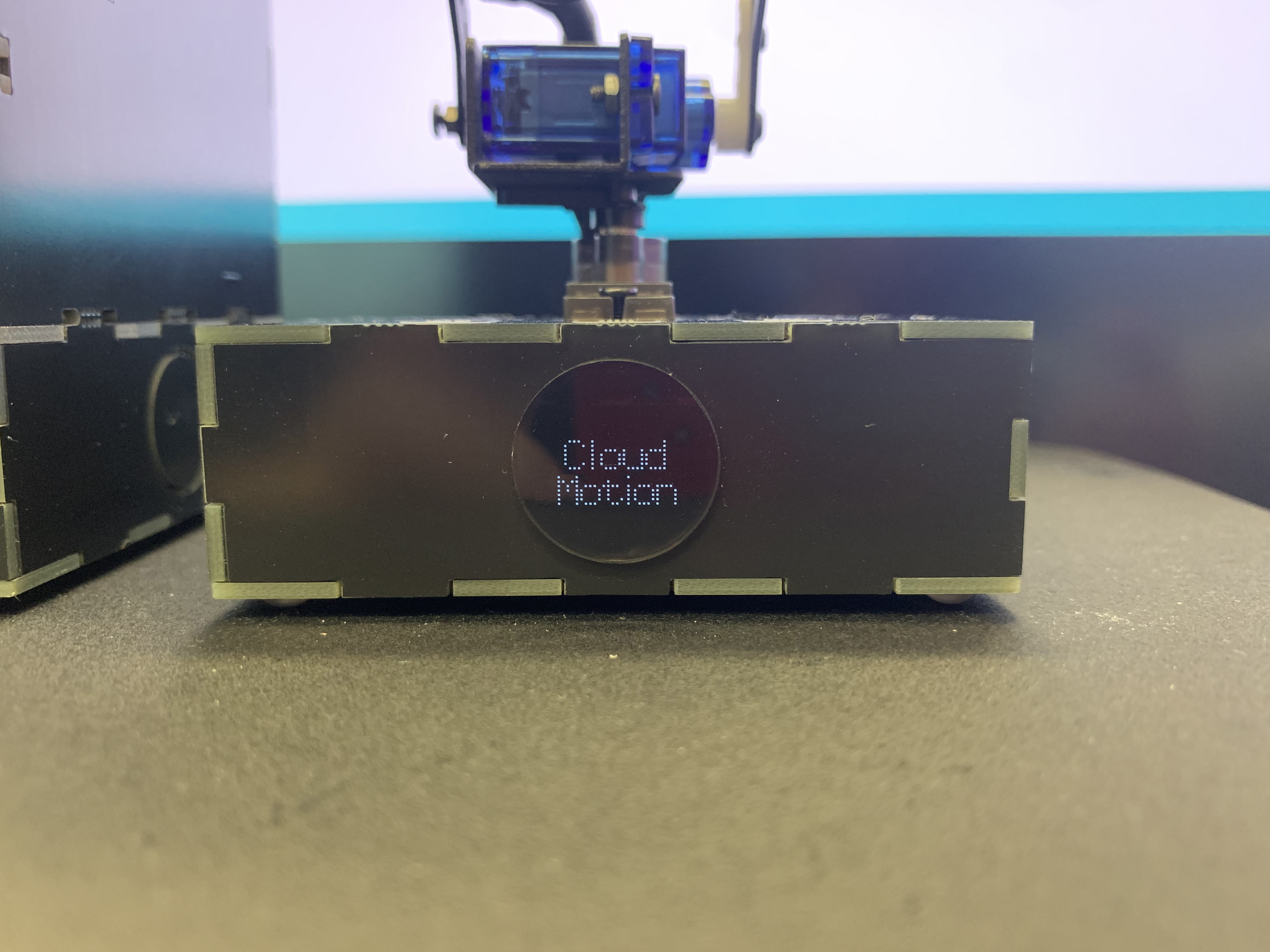
I have never liked the fonts that come with the GFX library, so I made a logo using dot matrix to display when powering on.
void display_logo()
{
  uint8_t cloud_Motion[5*12]=
  {
    0b00111110,0b01000001,0b01000001,0b01000001,0b00100010, // C
    0b00000000,0b00000000,0b01111111,0b00000000,0b00000000, // l
    0b00001110,0b00010001,0b00010001,0b00010001,0b00001110, // o
    0b00011110,0b00000001,0b00000001,0b00000001,0b00011111, // u
    0b00001110,0b00010001,0b00010001,0b00010001,0b01111111, // d
    //0b00000000,0b00000000,0b00000000,0b00000000,0b00000000, // space
    0b01111111,0b00100000,0b00011000,0b00100000,0b01111111, // M
    0b00001110,0b00010001,0b00010001,0b00010001,0b00001110, // o
    0b00010000,0b00111110,0b00010001,0b00010001,0b00000010, // t
    0b00000000,0b00000000,0b01011111,0b00000000,0b00000000, // i
    0b00001110,0b00010001,0b00010001,0b00010001,0b00001110, // o
    0b00011111,0b00010000,0b00010000,0b00010000,0b00001111, // n
  };
  uint16_t _x = 40;
  uint16_t _y = 0;
  for(uint8_t i=0;i<12;i++)
  {
    if((i == 1)||(i ==2))
    {
      _x = _x - 2;
    }
    if(i==9||(i==10))
    {
      _x = _x - 3;
    }
    if(i == 5)
    {
      _x = 32;
    }
    for(uint8_t m=0;m<5;m++)
    {
      if(i >= 5)
      {
        _y = 16;
      }
      else
      {
        _y = 0;
      }
      for(uint8_t n=0;n<8;n++)
      {
        if((cloud_Motion[i*5+m]>>(7-n))&0x01)
        {
          display.fillRect(_x+1, _y+1, 1, 1, SSD1306_WHITE);
        }
        _y += 2;
      }
      _x = _x + 2;
    }
  }
  display.display();
}
In Once mode, if TOF data is obtained, the current measurement results will be immediately displayed on this OLED screen.
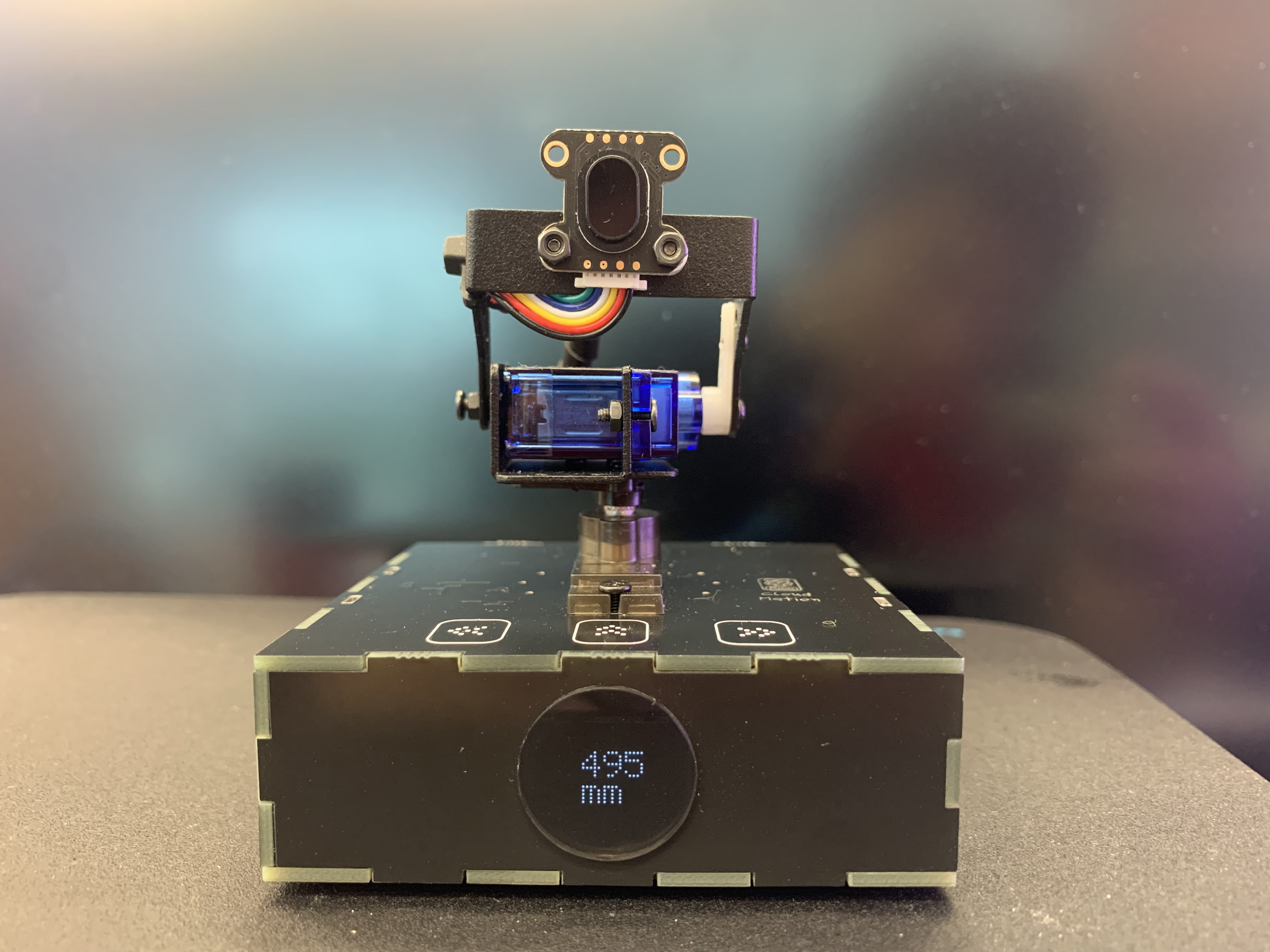
It is also important to be able to display locally, that is, it can work independently when not connected to the network or not connected to Cloud Pixel.TOF display code show as below:
void display_tof(uint16_t num)
{
  uint16_t _x = 0;
  uint16_t _y = 0;
  uint8_t between_space = 1;
  uint8_t display_byte[4];
  const uint8_t Repetition_Scrolling[10][5] = {
  {0b00111110,0b01000001,0b01000001,0b01000001,0b00111110}, // 0
  {0b00000000,0b00100001,0b01111111,0b00000001,0b00000000}, // 1
  {0b00100001,0b01000011,0b01000101,0b01001001,0b00110001}, // 2
  {0b00100010,0b01001001,0b01001001,0b01001001,0b00110110}, // 3
  {0b00001100,0b00010100,0b00100100,0b01111111,0b00000100}, // 4
  {0b01110010,0b01010001,0b01010001,0b01010001,0b01001110}, // 5
  {0b00011110,0b00101001,0b01001001,0b01001001,0b00000110}, // 6
  {0b01000011,0b01000100,0b01001000,0b01010000,0b01100000}, // 7
  {0b00110110,0b01001001,0b01001001,0b01001001,0b00110110}, // 8
  {0b00110000,0b01001001,0b01001001,0b01001010,0b00111100}  // 9
  };
  const uint8_t Repetition_Scrolling_mm[5] = {
  0b00011111,0b00010000,0b00011111,0b00010000,0b00001111 //m
  };
  if(num>4000){
    num = 4000;
  }
  display_byte[0] = (num/1000)%10;
  display_byte[1] = (num/100)%10;
  display_byte[2] = (num/10)%10;
  display_byte[3] = num%10;

  display.clearDisplay();
  if(display_byte[0] != 0)
  {
    _x = 40;//+(9 + between_space)*3;;
    _y = 0;
    for(uint8_t i =0;i<4;i++)
    {
      for(uint8_t m=0;m<5;m++)
      {
        _y = 0;
        for(uint8_t n=0;n<8;n++)
        {
          if((Repetition_Scrolling[display_byte[i]][m]>>(7-n))&0x01)
          {
            display.fillRect(_x+1, _y+1, 1, 1, SSD1306_WHITE);
          }
          _y += 2;
        }
        _x +=2;
      }
      _x += (between_space);
    }
  }
  else if(display_byte[1] != 0)
  {
    _x = 40 + 9 + between_space;
    _y = 0;
    for(uint8_t i =0;i<3;i++)
    {
      for(uint8_t m=0;m<5;m++)
      {
        _y = 0;
        for(uint8_t n=0;n<8;n++)
        {
          if((Repetition_Scrolling[display_byte[i+1]][m]>>(7-n))&0x01)
          {
            display.fillRect(_x+1, _y+1, 1, 1, SSD1306_WHITE);
          }
          _y += 2;
        }
        _x +=2;
      }
      _x += between_space;
    }
  }
  else if(display_byte[2] != 0)
  {
    _x = 40 + (9 + between_space)*2;
    _y = 0;
    for(uint8_t i =0;i<2;i++)
    {
      for(uint8_t m=0;m<5;m++)
      {
        _y = 0;
        for(uint8_t n=0;n<8;n++)
        {
          if((Repetition_Scrolling[display_byte[i+2]][m]>>(7-n))&0x01)
          {
            display.fillRect(_x+1, _y+1, 1, 1, SSD1306_WHITE);
          }
          _y += 2;
        }
        _x += 2;
      }
      _x += between_space;
    }
  }
  else
  {
    _x = 40 + (9 + between_space)*3;
    _y = 0;
    for(uint8_t m=0;m<5;m++)
    {
      _y = 0;
      for(uint8_t n=0;n<8;n++)
      {
        if((Repetition_Scrolling[display_byte[3]][m]>>(7-n))&0x01)
        {
          display.fillRect(_x+1, _y+1, 1, 1, SSD1306_WHITE);
        }
        _y += 2;
      }
      _x += 2;
    }
  }
  _x = 40 + (9 + between_space)*1;
  _y = 14;
  for(uint8_t m=0;m<5;m++)
  {
    _y = 14;
    for(uint8_t n=0;n<8;n++)
    {
      if((Repetition_Scrolling_mm[m]>>(7-n))&0x01)
      {
        display.fillRect(_x+1, _y+1, 1, 1, SSD1306_WHITE);
        display.fillRect(_x+1+11, _y+1, 1, 1, SSD1306_WHITE);
      }
      _y += 2;
    }
    _x += 2;
  }
  display.display();
}
Next we deal with the sending part of the code. The sending and synchronization issues of Adafruit have been fully explained in the previous project. In this project, I will focus on the communication with Coud Pixel. In this project, Cloud Motion mainly uses Ethernet W5100S for communication, while Cloud Pixel uses WiFi network module WizFi360 for communication.
The send_tof_to_cloud_Motion function is divided into two parts, corresponding to Once mode and Scan mode respectively.
void send_tof_to_cloud_Motion(void)
{
#ifdef Cloud_Pixel
  uint16_t tof_uint16_t[486];
  if(TOF_MODE == 0)
  {
    client.print(String("{MODE:0}{TOF_DATA_NUM:1}{TOF_X:")+String((servo_position_x-36)/2)+String("}{TOF_Y:")+String((servo_position_y-72)/2)+String("}{TOF_DATA:")+tof_data_uint16+String("}"));
  }
  else
  {
    client.print(String("{MODE:1}{TOF_DATA_NUM:3888}{TOF_DATA:"));
    delay(200);
    for(int q = 0; q<72; q++)
    {
      for(int p = 0; p<54; p++)
      {
        tof_uint16_t[(q%9)*54+p] = TOF_DATA[q][p];
      }
      if((q+1)%9 == 0)
      {
        client.write((uint8_t *)tof_uint16_t,972);
        Serial.write((uint8_t *)tof_uint16_t,972);
        delay(200);
      }
    }
    //client.print(String("}"));
  }
#endif
}
Once mode’s sending data format:
{MODE:0}{TOF_DATA_NUM:1}{TOF_X:")+String((servo_position_x-36)/2)+String("}{TOF_Y:")+String((servo_position_y-72)/2)+String("}{TOF_DATA:")+tof_data_uint16+String("}Because there is a lot of data in Scan mode, there are 7776 bytes of data each time. We grouped it and sent 972 bytes of data each time. The data format is:
"{MODE:1}{TOF_DATA_NUM:3888}{TOF_DATA:(7776 Byte)The above is the implementation process of all functions of Cloud Motion in this project.
Cloud Pixel code section in 3D Laser Radar project
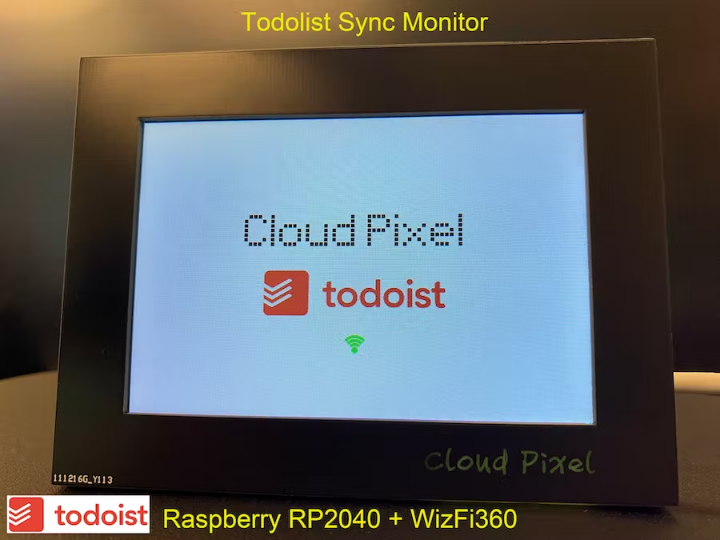
Cloud Pixel is a network device I developed earlier this year. It is mainly used to display network content. This is also the origin of the name Cloud Pixel.
I have developed multiple applications using Cloud Pixel, and several more are under development or planned.
Todolist Sync Monitor (Raspberry Pi Pico & WizFi360)
https://maker.wiznet.io/gavinchang/projects/raspberry-pi-pico-wizfi360-todolist-sync-monitor/
ChatGPT Recorder & Monitor(Raspberry Pi Pico & WizFi360)
https://maker.wiznet.io/gavinchang/projects/chatgpt-recorder-monitor-raspberry-pi-pico-wizfi360/
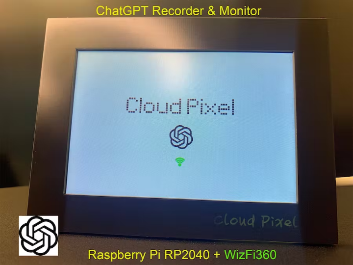
Cloud Pixel is one of my favorite pieces of hardware because a lot of thought was put into its design. I really like the design on the back, which looks like the sewer pipe maze in Super Mario.
The device initialization process of Cloud Pixel has been fully introduced in the previous project, and it is no longer time consuming this time. Just describe the different parts.
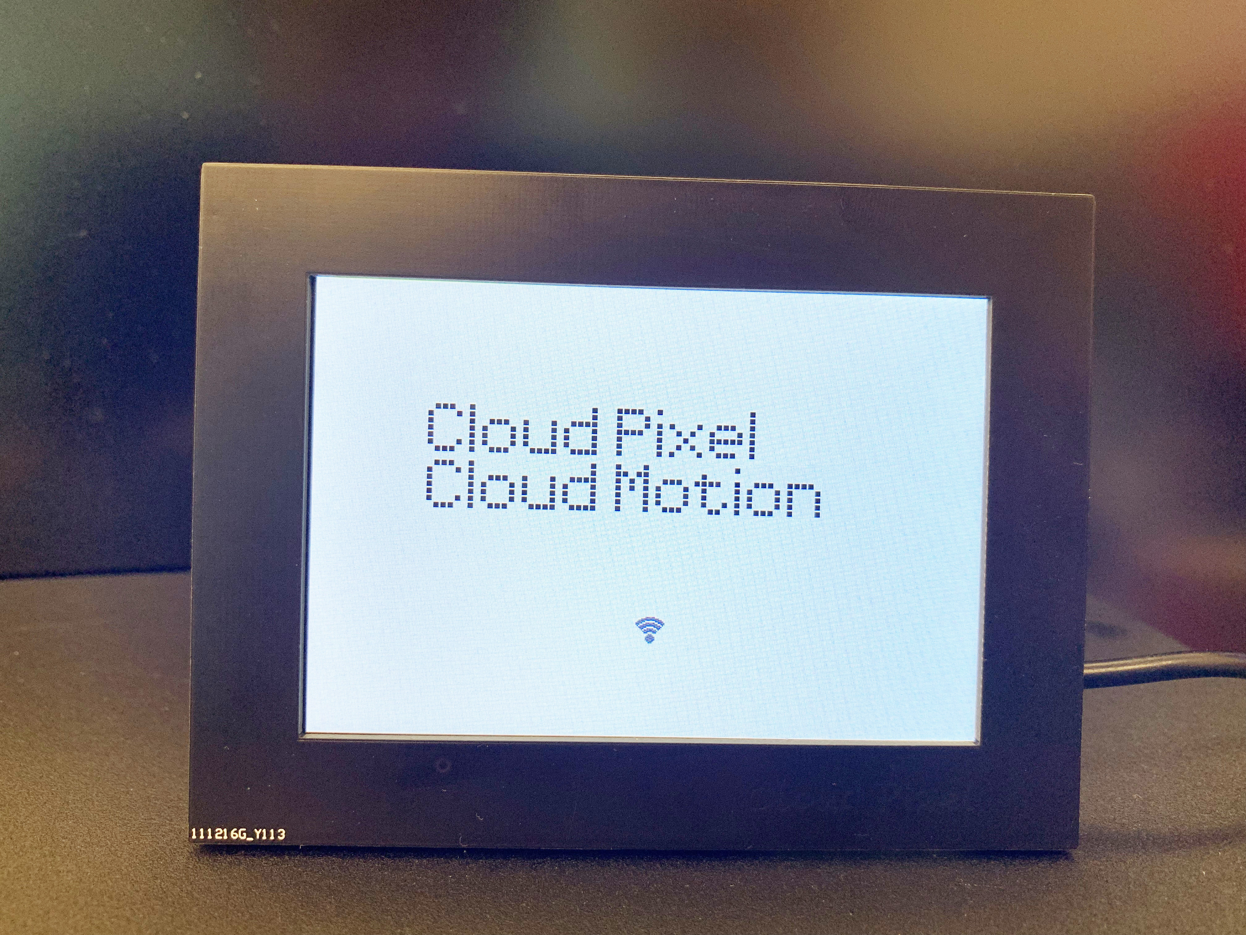
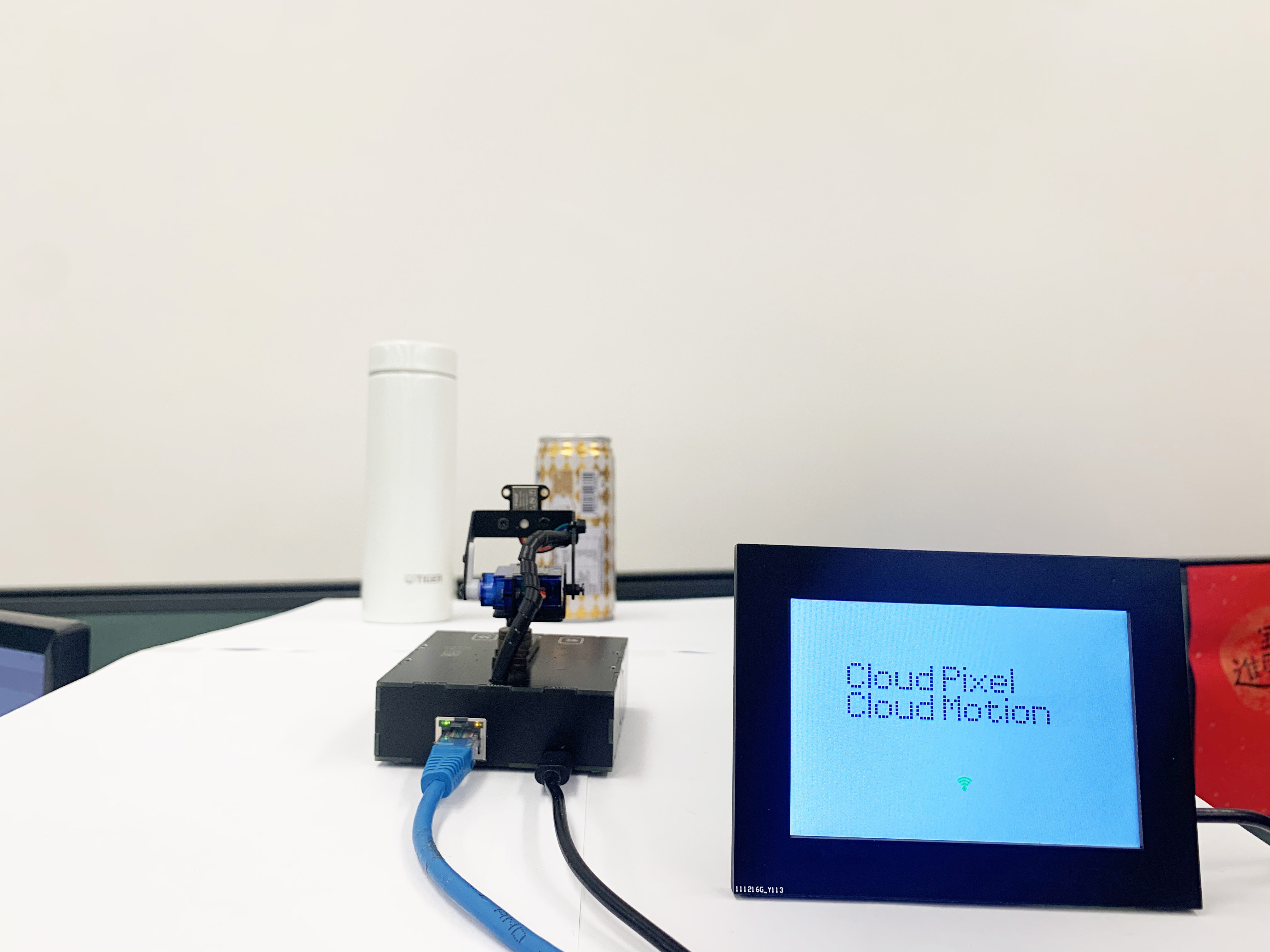
When powered on, the dot matrix LOGOs of Cloud Pixel and Cloud Motion are displayed. The code is as follows:
void display_logo(uint16_t x,uint16_t y,uint16_t color)
{
  uint8_t cloud_pixel[5*11]=
  {
    0b00111110,0b01000001,0b01000001,0b01000001,0b00100010, // C
    0b00000000,0b00000000,0b01111111,0b00000000,0b00000000, // l
    0b00001110,0b00010001,0b00010001,0b00010001,0b00001110, // o
    0b00011110,0b00000001,0b00000001,0b00000001,0b00011111, // u
    0b00001110,0b00010001,0b00010001,0b00010001,0b01111111, // d
    0b00000000,0b00000000,0b00000000,0b00000000,0b00000000, // space
    0b01111111,0b01001000,0b01001000,0b01001000,0b00110000, // P
    0b00000000,0b00000000,0b01011111,0b00000000,0b00000000, // i
    0b00010001,0b00001010,0b00000100,0b00001010,0b00010001, // x
    0b00001110,0b00010101,0b00010101,0b00010101,0b00001100, // e
    0b00000000,0b00000000,0b01111111,0b00000000,0b00000000  // l
  };
  uint8_t cloud_Motion[5*13]=
  {
    0b00111110,0b01000001,0b01000001,0b01000001,0b00100010, // C
    0b00000000,0b00000000,0b01111111,0b00000000,0b00000000, // l
    0b00001110,0b00010001,0b00010001,0b00010001,0b00001110, // o
    0b00011110,0b00000001,0b00000001,0b00000001,0b00011111, // u
    0b00001110,0b00010001,0b00010001,0b00010001,0b01111111, // d
    0b00000000,0b00000000,0b00000000,0b00000000,0b00000000, // space
    0b01111111,0b00100000,0b00011000,0b00100000,0b01111111, // M
    0b00001110,0b00010001,0b00010001,0b00010001,0b00001110, // o
    0b00011100,0b00000010,0b00000001,0b00000010,0b00011100, // v
    0b00010000,0b00111110,0b00010001,0b00010001,0b00000010, // t
    0b00000000,0b00000000,0b01011111,0b00000000,0b00000000, // i
    0b00001110,0b00010001,0b00010001,0b00010001,0b00001110, // o
    0b00011111,0b00010000,0b00010000,0b00010000,0b00001111, // n
  };
  uint16_t _x = x - (5*5*5) - 46;
  uint16_t _y = y - 40;
  for(uint8_t i=0;i<11;i++)
  {
    if(i == 1 || i == 2 || i ==5 || i==6 ||i==7 ||i==8 || i == 10)
    {
       _x = _x -6;
    }
    else
    {
       _x = _x+4;
    }
    for(uint8_t m=0;m<5;m++)
    {
      _x = _x +5;
      _y = y - 40;
      for(uint8_t n=0;n<8;n++)
      {
        if((cloud_pixel[i*5+m]>>(7-n))&0x01)
        {
          tft->fillRect(_x+1,_y+1,4,4,color);
        }
        _y += 5;
      }
    }
  }
  _x = x - (5*5*5) - 46;
  _y = y;
  for(uint8_t i=0;i<13;i++)
  {
    if(i == 1 || i == 2 || i ==5 || i==6 ||i==10 ||i==11)
    {
       _x = _x -6;
    }
    else
    {
       _x = _x+4;
    }
    for(uint8_t m=0;m<5;m++)
    {
      _x = _x +5;
      _y = y;
      for(uint8_t n=0;n<8;n++)
      {
        if((cloud_Motion[i*5+m]>>(7-n))&0x01)
        {
          tft->fillRect(_x+1,_y+1,4,4,color);
        }
        _y += 5;
      }
    }
  }
}
After the device is initialized and has been connected to the WiFi network and can receive data, the signal symbol at the middle and bottom of the screen will change from gray to green.

In Loop(), it is mainly a state machine function.
void loop(){
  switch(currentState){
    case listen_to_cloud_motion:
       {
          // listen for incoming clients
          client = server.available();
          if (client)
          {
            Serial.println("new client");
            // an http request ends with a blank line
            bool currentLineIsBlank = true;
            if (client.connected())
            {
              currentState = get_tof_from_cloud_motion;
            }
          }
       }
       break;
    case get_tof_from_cloud_motion:
       {
          while (client.available()){
            char c = client.read();
            //Serial.print(c);
            json_String += c;
          }
          if((json_String.length()> 0)&&(TOF_MODE == 2))
          {
            dataStart = json_String.indexOf("{MODE:") + strlen("{MODE:");
            dataEnd = json_String.indexOf("}{", dataStart);
            TOF_MODE = json_String.substring(dataStart, dataEnd).toInt();
          }
          if(TOF_MODE == 0)
          {
             Serial.println(json_String);
             Serial.println(TOF_MODE);
             currentState = display_tof_on_cloud_pixel;
          }
          else if(TOF_MODE == 1)
          {
            uint16_t num = 0;
            while (num!= 7776)
            {
              while (client.available()){
                *((uint8_t*)(TOF_SCAN_DATA) + num) = client.read();
                 num++;
              }
            }
            currentState = display_tof_on_cloud_pixel;
          }
       }
       break;
    case display_tof_on_cloud_pixel:
       {
          display_dashboard();
          TOF_MODE_LAST = TOF_MODE;
          TOF_MODE = 2;
          json_String= "";
          if (client.connected())
          {
            currentState = get_tof_from_cloud_motion;
          }
          else
          {
            currentState = listen_to_cloud_motion;
          }
       }
       break;
  }
}"case listen_to_cloud_motion":Wait for Cloud Motion to connect;
"case get_tof_from_cloud_motion": receive TOF data;
"case display_tof_on_cloud_pixel":display TOF data on the screen.
When receiving data, you need to receive the first character to determine the TOF mode. If it is equal to 0, it is Once mode. If it is equal to 1, it is Scan mode.
This is the display interface in Once mode. There will be a red dot indicating the relative position in all dots. There are several windows on the right showing "mode", "X-axis position", "Y-axis position", "distance", etc.
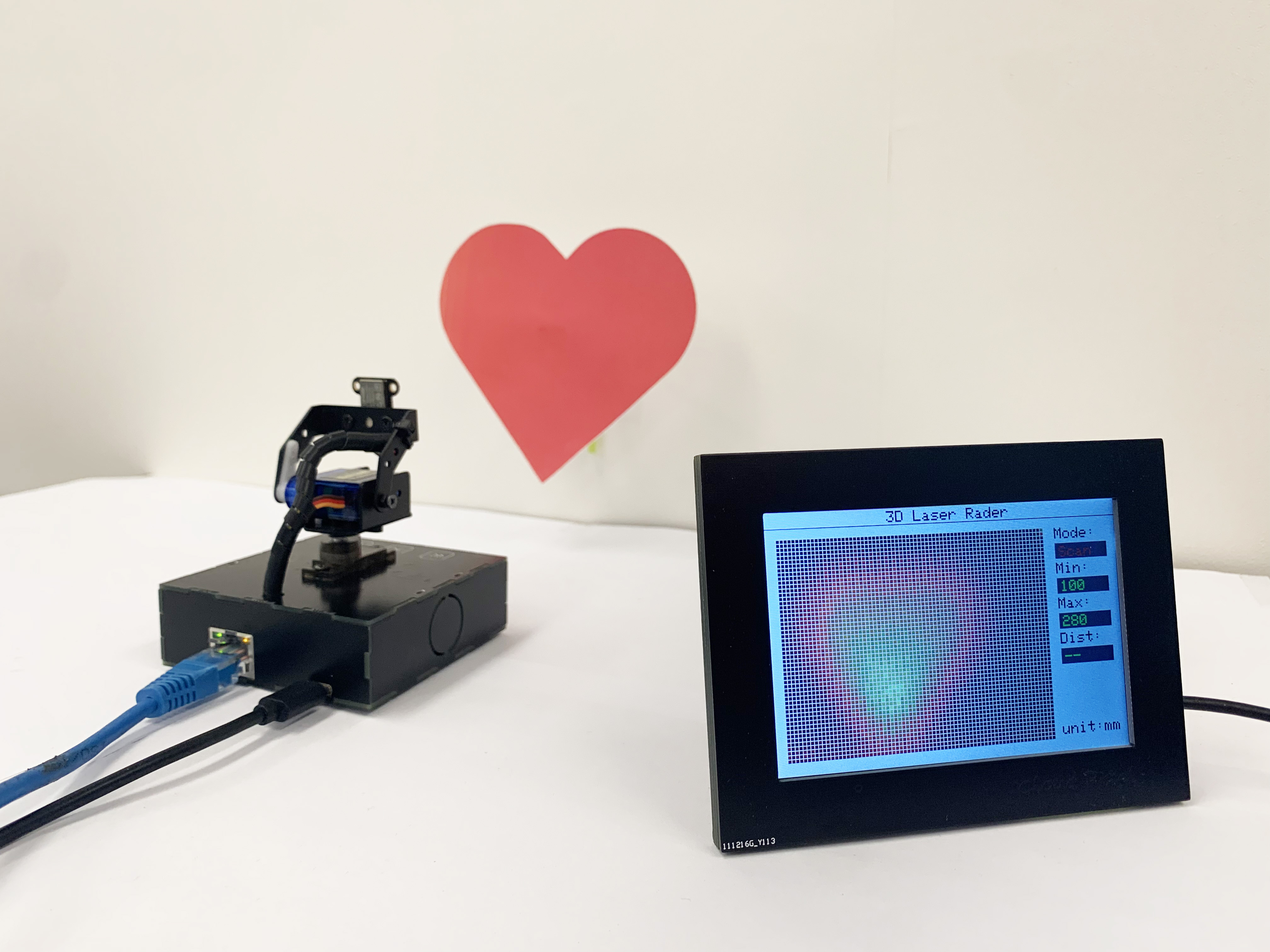
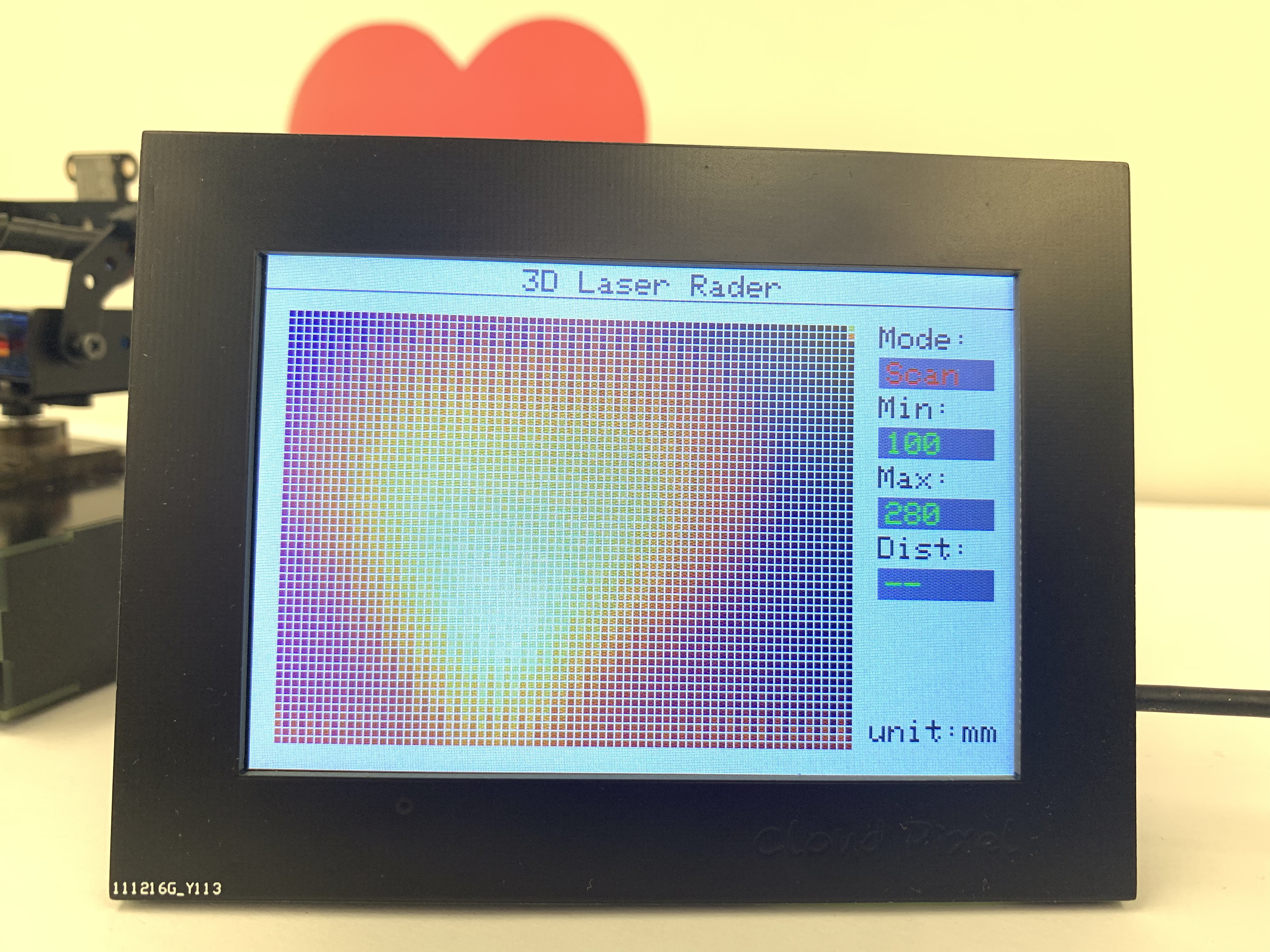
In Scan mode, it is necessary to receive all complete TOF data, and then replace it with color information based on the map of the comparison dot matrix, so as to display it in the dot matrix map of the screen.It will also compare all the data to determine the farthest point and the latest point in the distance information, and display them in the window on the right. “Min” and“Max”.
The processing code for the screen display part is as follows:
void display_dashboard()
{
  uint16_t _x = 0;
  uint16_t _y = 0;
  int32_t pixelVal;
  int16_t lutIndex;
  if(fillScreen_ == true)
  {
    tft->fillScreen(WHITE);
    for(int q = 0; q<72; q++)
    {
      for(int p = 0; p<54; p++)
      {
        _x = q*5+15;
        _y = p*5+35;
        tft->fillRect(_x,_y,4,4,LIGHTGREY);
      }
    }
    fillScreen_ = false;
  }
  tft->setTextColor(DARKGREY);
  tft->setTextSize(2);
  tft->setCursor(160, 4);
  tft->print(String("3D Laser Rader"));// (Cloud Pixel & Cloud Motion)"));
  tft->setCursor(390, 35);
  tft->print(String("Mode:"));
  tft->fillRect(390,55,75,20,LIGHTGREY);
  tft->setCursor(390, 170);
  tft->print(String("Dist:"));
  tft->fillRect(390,190,75,20,LIGHTGREY);
  tft->setCursor(385, 285);
  tft->print(String("unit:mm"));

  tft->drawLine(0,21,480,21,DARKGREY);

  if((TOF_MODE_LAST == 1)&&(TOF_MODE == 0))
  {
    for(int q = 0; q<72; q++)
    {
      for(int p = 0; p<54; p++)
      {
        _x = q*5+15;
        _y = p*5+35;
        tft->fillRect(_x,_y,4,4,LIGHTGREY);
      }
    }
  }
  if(TOF_MODE == 0)
  {
    tft->fillRect(TOF_X*5+15,TOF_Y*5+35,4,4,LIGHTGREY);
    dataStart = json_String.indexOf("{TOF_X:") + strlen("{TOF_X:");
    dataEnd = json_String.indexOf("}{", dataStart);
    TOF_X = json_String.substring(dataStart, dataEnd).toInt();
    dataStart = json_String.indexOf("{TOF_Y:") + strlen("{TOF_Y:");
    dataEnd = json_String.indexOf("}{", dataStart);
    TOF_Y = json_String.substring(dataStart, dataEnd).toInt();
    dataStart = json_String.indexOf("TOF_DATA:") + strlen("TOF_DATA:");
    dataEnd = json_String.indexOf("}", dataStart);
    TOF_DATA = json_String.substring(dataStart, dataEnd).toInt();

    tft->fillRect(390,80,75,20,WHITE);
    tft->setCursor(390, 80);
    tft->print(String("X:"));
    tft->fillRect(390,100,75,20,LIGHTGREY);
    tft->fillRect(390,125,75,20,WHITE);
    tft->setCursor(390, 125);
    tft->print(String("Y:"));
    tft->fillRect(390,145,75,20,LIGHTGREY);

    tft->setTextColor(RED);
    tft->setCursor(395, 58);
    tft->print(String("Once"));
    tft->setTextColor(GREEN);
    tft->setCursor(395, 103);
    tft->print(TOF_X);
    tft->setCursor(395, 148);
    tft->print(TOF_Y);
    tft->setCursor(395, 193);
    tft->print(TOF_DATA);
    tft->fillRect(TOF_X*5+15,TOF_Y*5+35,4,4,RED);
  }
  if(TOF_MODE == 1)
  {
    uint16_t tof_min = 1000;
    uint16_t tof_max = 0;
    for(int q = 0; q<72; q++)
    {
      for(int p = 0; p<54; p++)
      {
        if(TOF_SCAN_DATA[q*54+p]!=4000)
        {
          if(TOF_SCAN_DATA[q*54+p]>tof_max)
          {
            tof_max = TOF_SCAN_DATA[q*54+p];
          }
          if(tof_min > TOF_SCAN_DATA[q*54+p])
          {
            tof_min = TOF_SCAN_DATA[q*54+p];
          }
        }
      }
    }
    Serial.print("tof_min:");
    Serial.println(tof_min);
    Serial.print("tof_max:");
    Serial.println(tof_max);

    tft->setTextColor(RED);
    tft->setCursor(395, 58);
    tft->print(String("Scan"));
    tft->fillRect(390,80,75,20,WHITE);
    tft->setTextColor(DARKGREY);
    tft->setCursor(390, 80);
    tft->print(String("Min:"));
    tft->fillRect(390,100,75,20,LIGHTGREY);
    tft->setTextColor(GREEN);
    tft->setCursor(395, 103);
    tft->print(tof_min);

    tft->fillRect(390,125,75,20,WHITE);
    tft->setTextColor(DARKGREY);
    tft->setCursor(390, 125);
    tft->print(String("Max:"));
    tft->fillRect(390,145,75,20,LIGHTGREY);
    tft->setTextColor(GREEN);
    tft->setCursor(395, 148);
    tft->print(tof_max);

    tft->setCursor(395, 193);
    tft->print("--");
    tft->fillRect(TOF_X*5+15,TOF_Y*5+35,4,4,RED);

    for(int q = 0; q<72; q++)
    {
      for(int p = 0; p<54; p++)
      {
        if(TOF_SCAN_DATA[q*54+p]==4000)
        {
          TOF_SCAN_DATA[q*54+p] = tof_max;
        }
        if(TOF_SCAN_DATA[q*54+p]==0)
        {
          TOF_SCAN_DATA[q*54+p] = tof_min;
        }
      }
    }
    // =========================================================================
    // Colour conversion - one pixel at a time
    // The draw_buffer starts as 16 bit sensor data
    // At the end it is 16 bit RGB (5-6-5)
    // =========================================================================
    for(int q = 0; q<72; q++)
    {
      for(int p = 0; p<54; p++)
      {
        Serial.print(q);
        Serial.print("-");
        Serial.print(p);
        Serial.print("-");
        Serial.print(q*54+p);
        Serial.print(":");
        Serial.println(TOF_SCAN_DATA[q*54+p]);
        lutIndex = map (TOF_SCAN_DATA[q*54+p], tof_min, tof_max , 0x00, 0xff);  // Data is in range so map it LUT index between low and high defaults
        _x = (71-q)*5+15;
        _y = p*5+35;
        tft->fillRect(_x,_y,4,4,palette[255-lutIndex]);
      }
    }
  }
}
testing:

Done!
-
Cloud_Motion_3D_Laser_Rader

-
Cloud_Pixel_3D_Laser_Rader