
3D Laser Radar Tower based on 2-degree-of-freedom network gimbal (POE+PICO)
Dynamic scanning of lidar is performed through 2-degree-of-freedom network gimbal to form a 3D photo containing distance information.

Raspberry Pi - RP2040
x 1
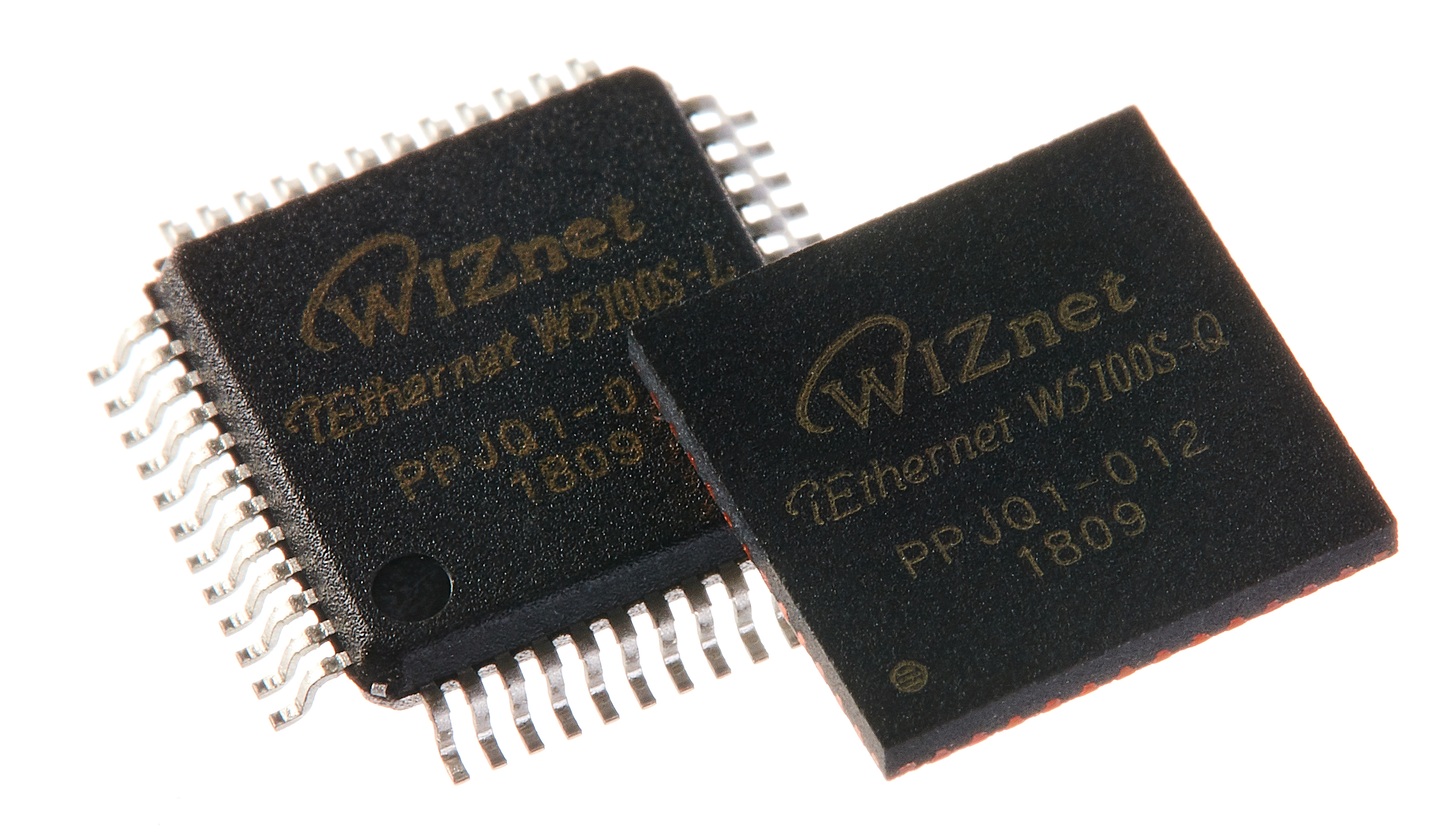
WIZnet - W5100S
x 1
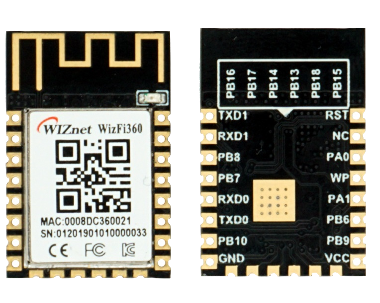
WIZnet - WizFi360
x 1
Tower Pro - SG90 SERVO
x 1

Arduino - Arduino IDE
x 1
3D Laser Radar Tower based on 2-degree-of-freedom network gimbal (POE+PICO).Dynamic scanning of lidar is performed through 2-degree-of-freedom network gimbal to form a 3D photo containing distance information.
The premise of this project is to use the simplest components, add the network, and explore more interesting ways of using it.
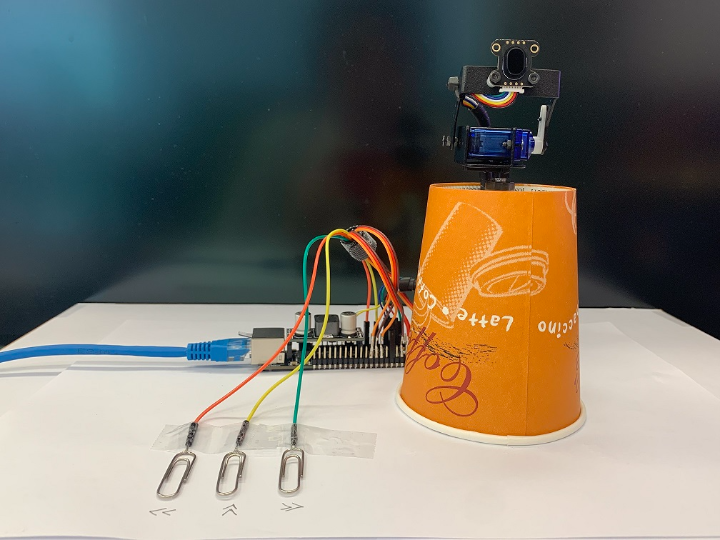
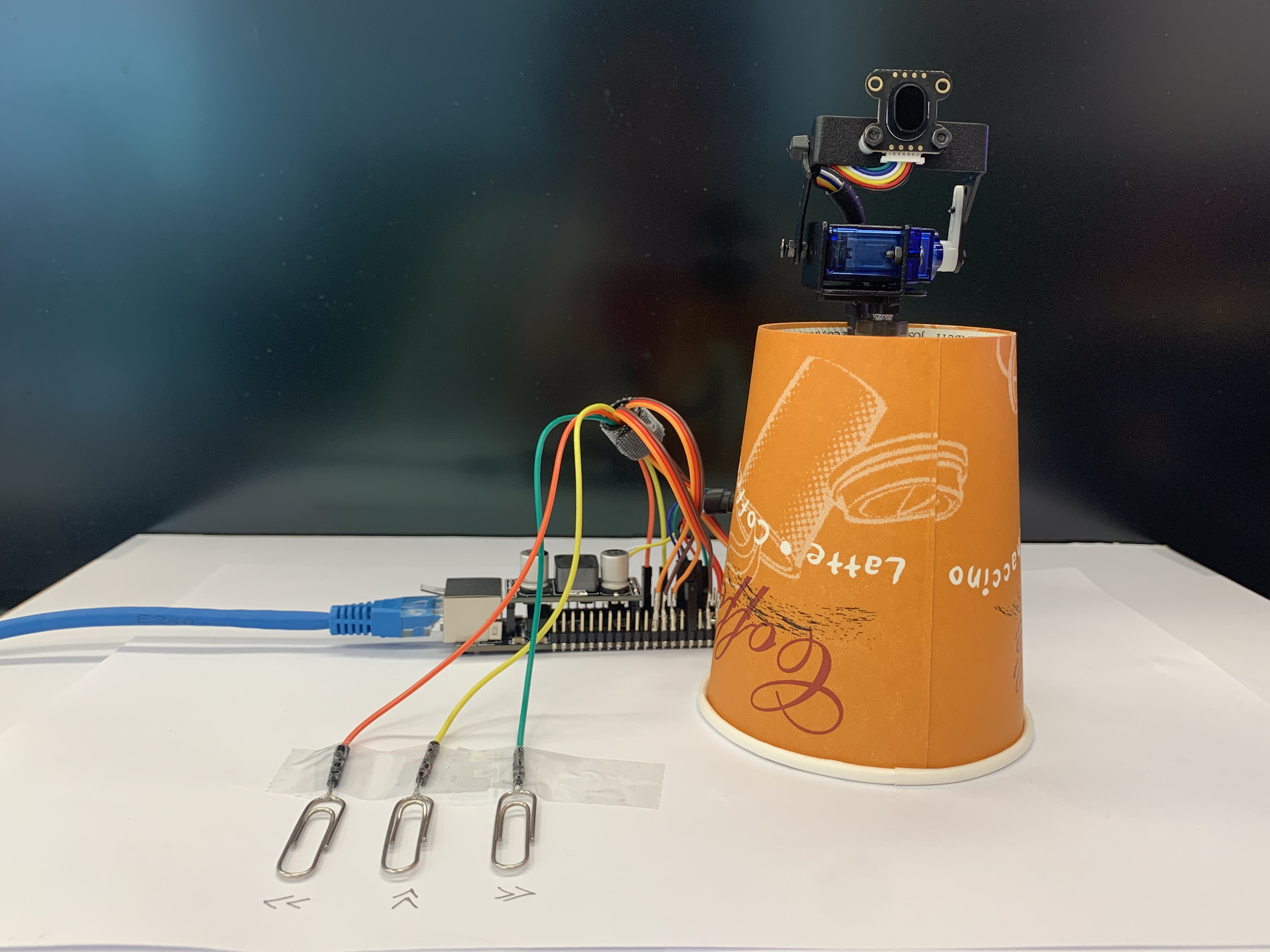
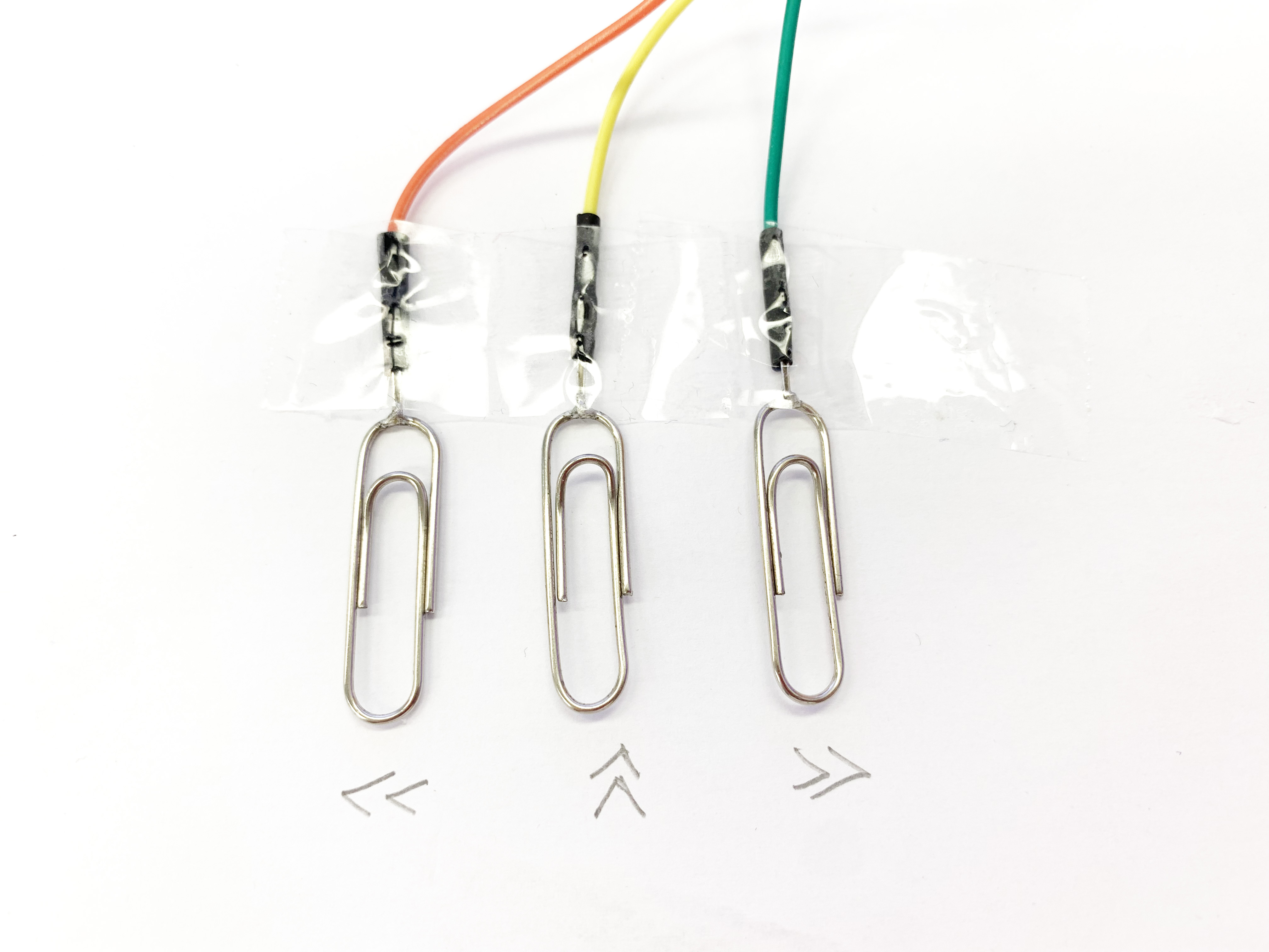
As a typical component of the “Tower” series, the paper clip still functions as a touch button, and the three buttons serve as "<<", "^^", and ">>" respectively.
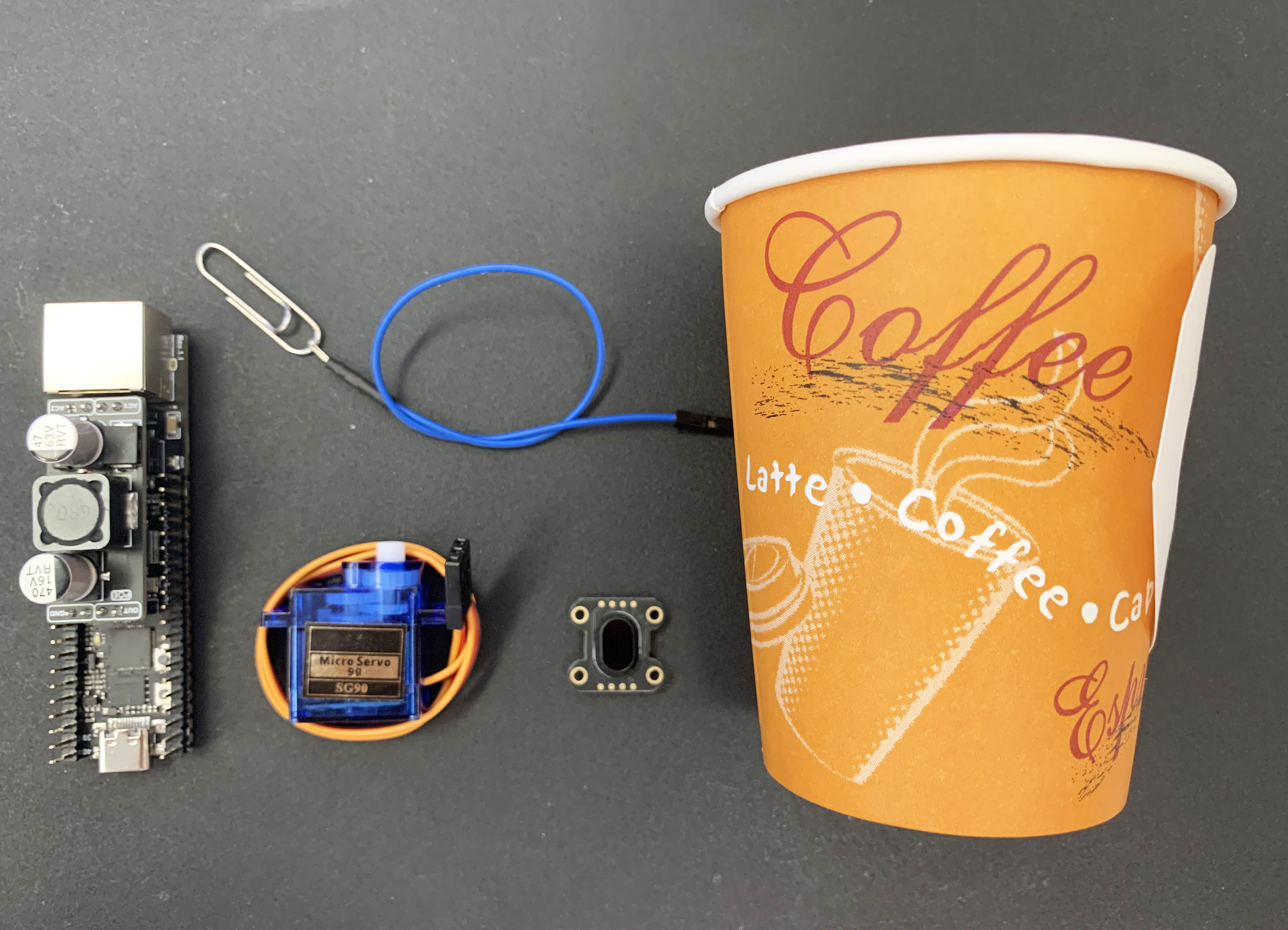
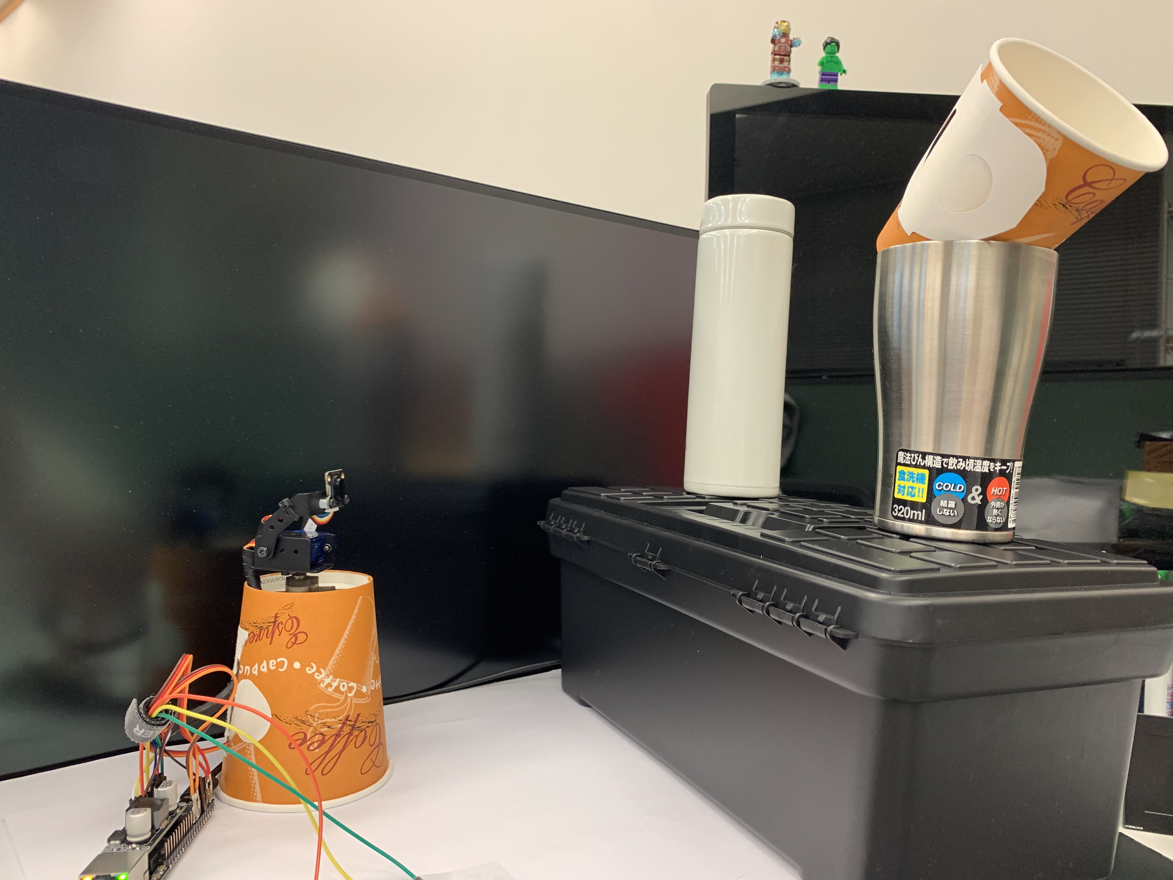
The 3D Laser Radar Tower uses 2 Servos to form a 2-degree-of-freedom network gimbal, and uses a laser ranging module TOF-400F to provide distance information. And the information is transmitted through W5100S_POE_EVB_PICO, which provides power.
all components used are shown in the figure below.
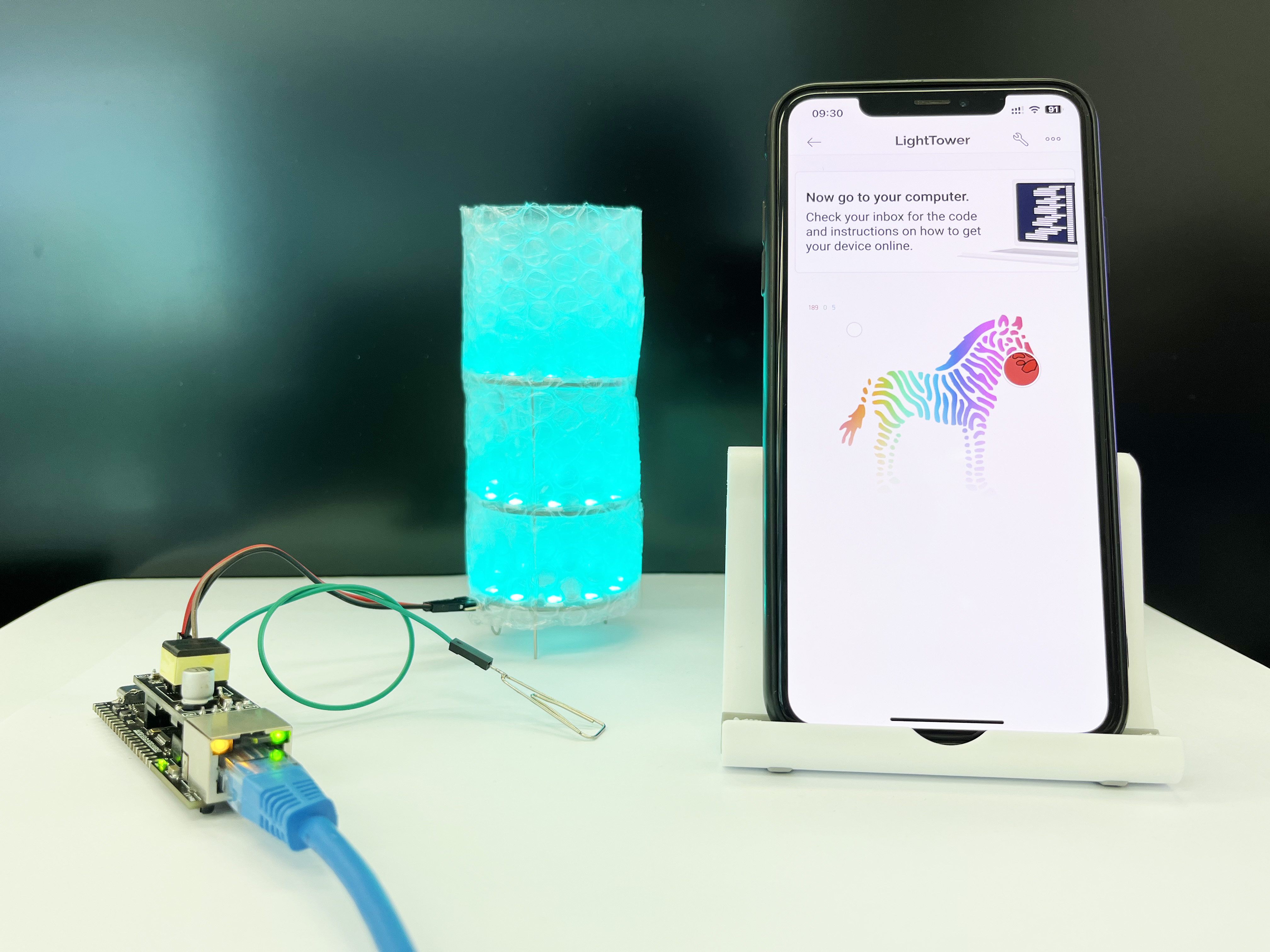
The other two projects in the “Tower ” series are Light Tower and Remote Control Tower.
Light Tower:
https://maker.wiznet.io/gavinchang/projects/light-tower-powered-by-poe-pico-w5100s-poe-evb-pico/
Remote Control Tower:
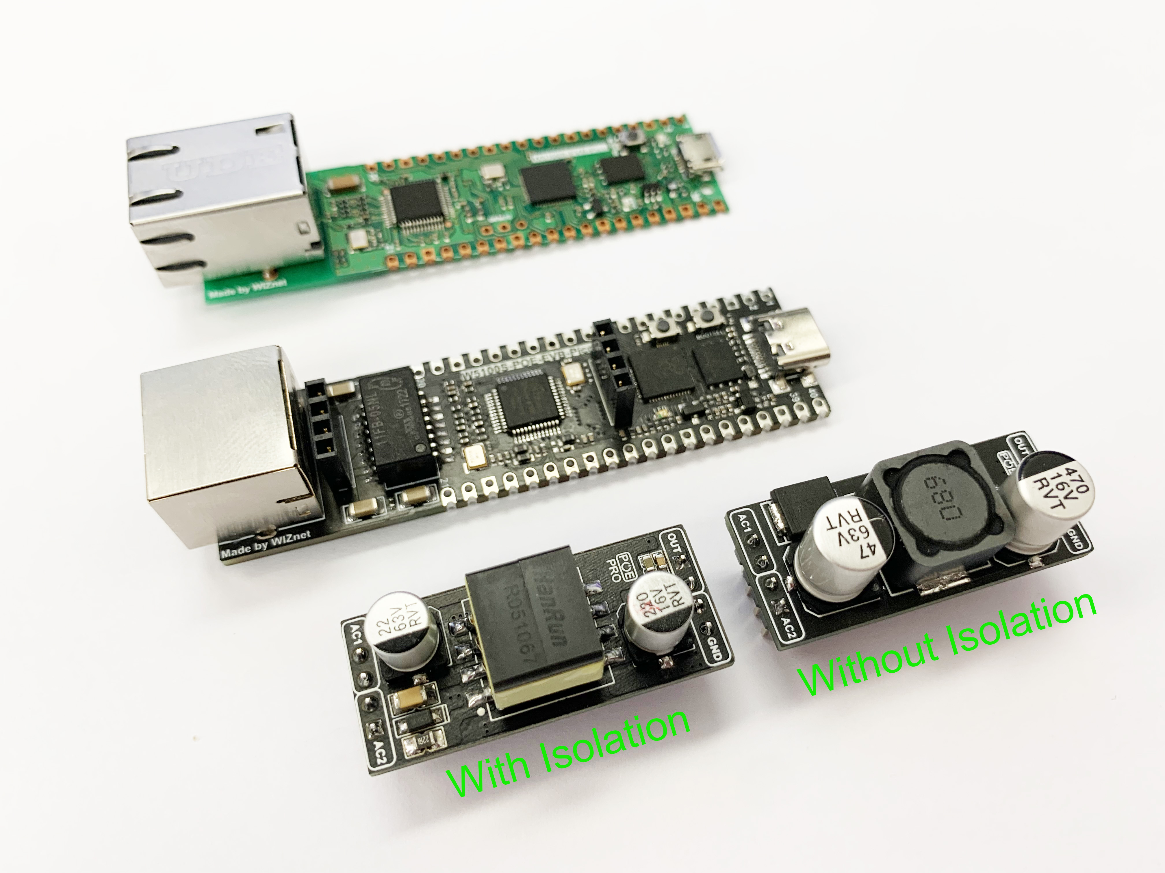
The main control board I use is W5100S_POE_EVB_PICO, which can be understood as W5100S_EVB_PICO with POE function. The external Pin of both is fully compatible, except that the original Micro USB interface is changed to a Type C interface.
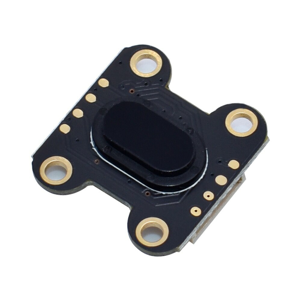
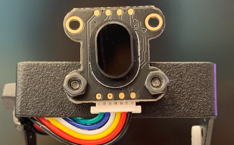
The core device of the 3D Laser Radar Tower project is the laser TOF module. I use TOF-400F, which can return the distance information of the target object very accurately, and because of the physical characteristics of laser TOF, it is more accurate than acoustic TOF. There is direction and accuracy.
The picture below shows the principle of laser TOF. There are three products in this series.TOF-050F,TOF-200F and TOF-400F. I chose the one with the longest TOF distance.
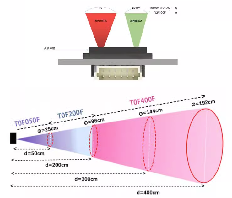
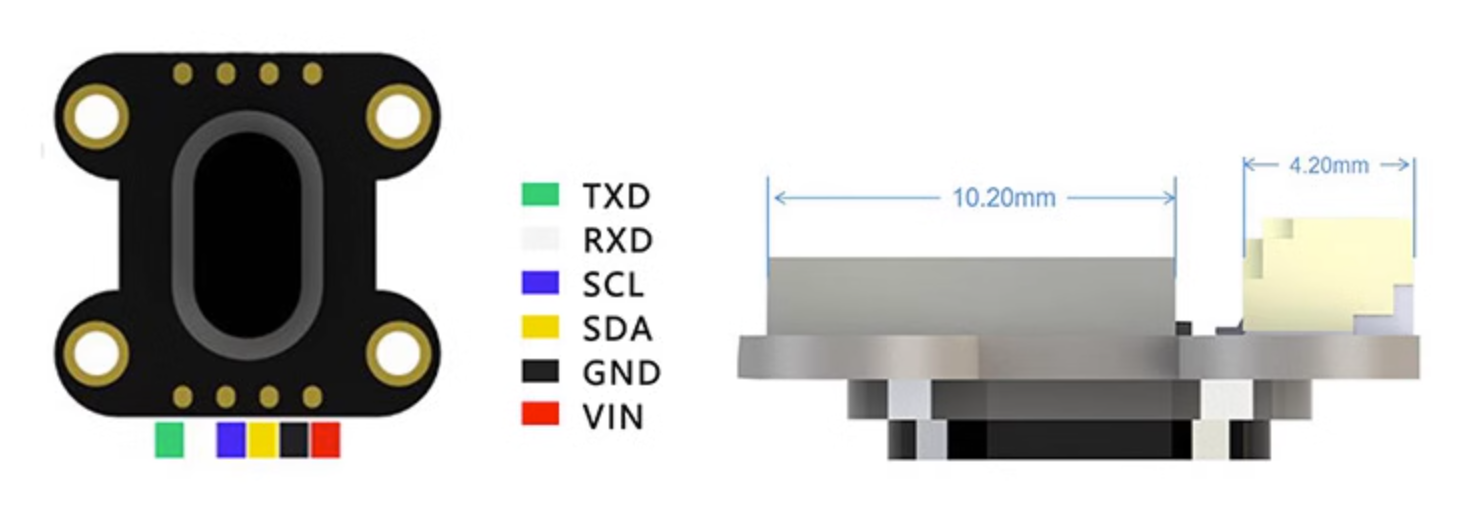
It has two interfaces, namely I2C and UART.
TOF-400F has a small size and weight, which makes it easy for me to install it on the top of the 2-degree-of-freedom gimbal and follow the movements of the upper gimbal.
I am using the software serial port, through the following definition:
SoftwareSerial DT(2, 3); //RX--2 TX--3TOF-400F only requires simple configuration to use. These are the parameters that need to be configured when powering on.
//////////////////////////////////// Instruction Set ///////////////////////////////////////////////
const byte SYSCMD[4][8] = {
  {0x01, 0x06, 0x00, 0x20, 0x00, 0x8C, 0x89, 0xA5},// 01 06 00 20 00 8C 89 A5 Set offset calibration distance to 140mm
  {0x01, 0x06, 0x00, 0x21, 0x00, 0x64, 0xD8, 0x2B},// 01 06 00 21 00 64 D8 2B Set xtalk calibration distance to 100mm
  {0x01, 0x06, 0x00, 0x06, 0x00, 0x01, 0xA8, 0x0B},// 01 06 00 06 00 01 A8 0B Load calibration
  {0x01, 0x06, 0x00, 0x01, 0x10, 0x00, 0xD5, 0xCA},// 01 06 00 01 10 00 D5 CA Restart distance measuring module
};
const byte distanceCMD[2][8] = {
  {0x01, 0x06, 0x00, 0x04, 0x00, 0x00, 0xC8, 0x0B},// 01 06 00 04 00 00 C8 0B Set TOF400 measuring range to 1.3m / Set TOF200 measuring range to default
  {0x01, 0x06, 0x00, 0x04, 0x00, 0x01, 0x09, 0xCB},// 01 06 00 04 00 01 09 CB Set TOF400 measuring range to 4.0m / Set TOF200 measuring range to high precision
};
const byte timeCMD[1][8] = {
  {0x01, 0x06, 0x00, 0x05, 0x00, 0x32, 0x18, 0x1E},// 01 06 00 05 00 32 18 1E Set continuous output and output time interval to 50MS
};
These are the operations required by the TOF module in the Setup() section:
  DT.begin(115200);

  shortdistance();
  //longdistance();
  delay(2000);

  outputTIME50MS();//Output timeout 50MS
  delay(2000);

  modRST();//Reset TOF module
  delay(2000);
These are the functions code required by the TOF module:
//*********************SYS System Settings*************************//
//*********Distance Module Restart Function
void modRST()// Distance module restart
{
for (int i = 0; i < 8; i++)
DT.write(SYSCMD[3][i]);
}
//*********Distance Output Time Interval Function
void outputTIME50MS()// Output time interval 50ms
{
for (int i = 0; i < 8; i++)
DT.write(timeCMD[0][i]);
}
//*************Mode Selection****************************//
void shortdistance()// Short distance mode
{
for (int i = 0; i < 8; i++)
DT.write(distanceCMD[0][i]);
}
void longdistance()// Long distance mode
{
for (int i = 0; i < 8; i++)
DT.write(distanceCMD[1][i]);
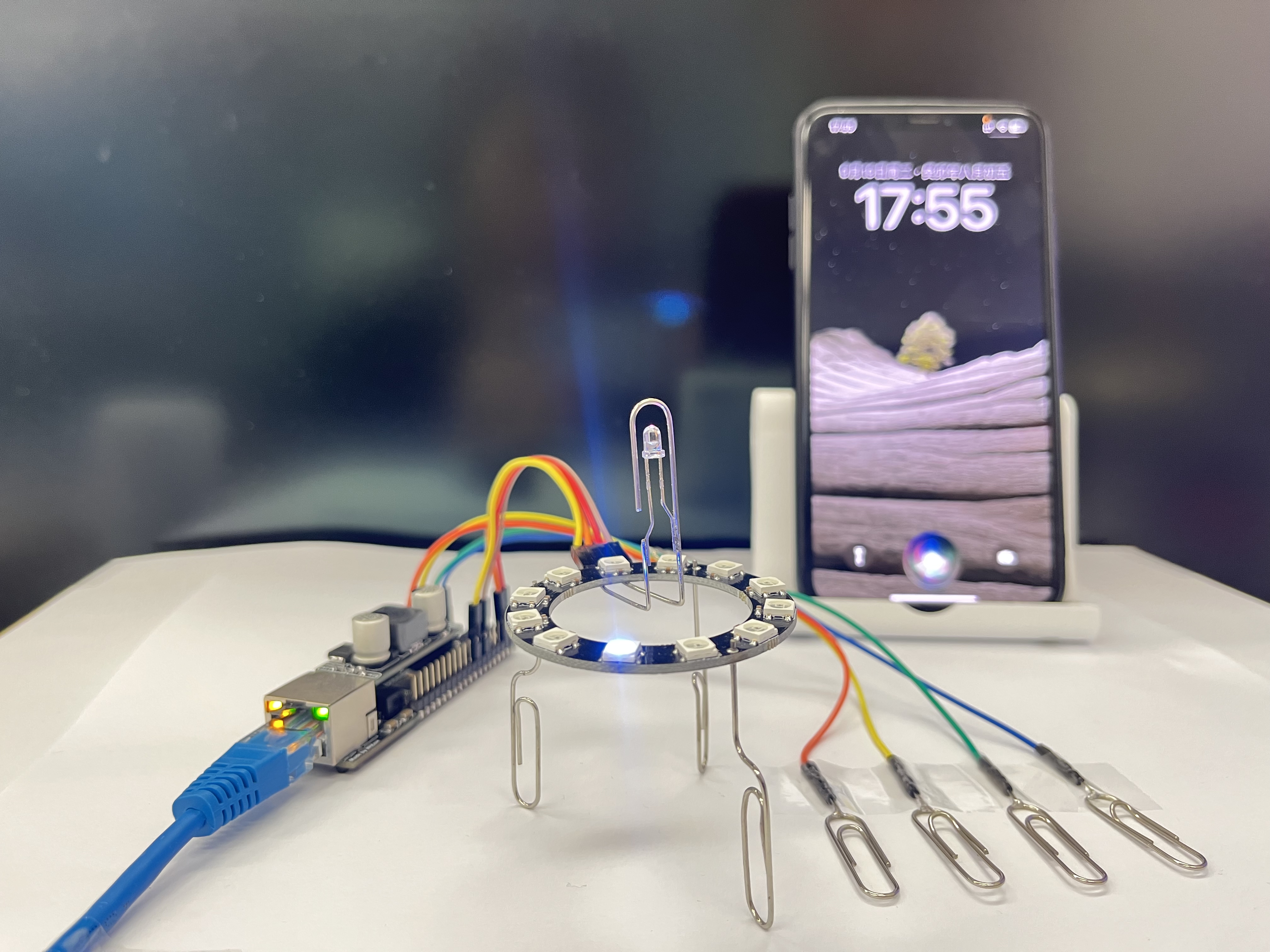
}The 2-degree-of-freedom gimbal consists of two Servos. The lower Servo is responsible for horizontal movements, and the upper Servo is responsible for vertical movements. A hole is cut into the paper cup to accommodate the entire motion platform.
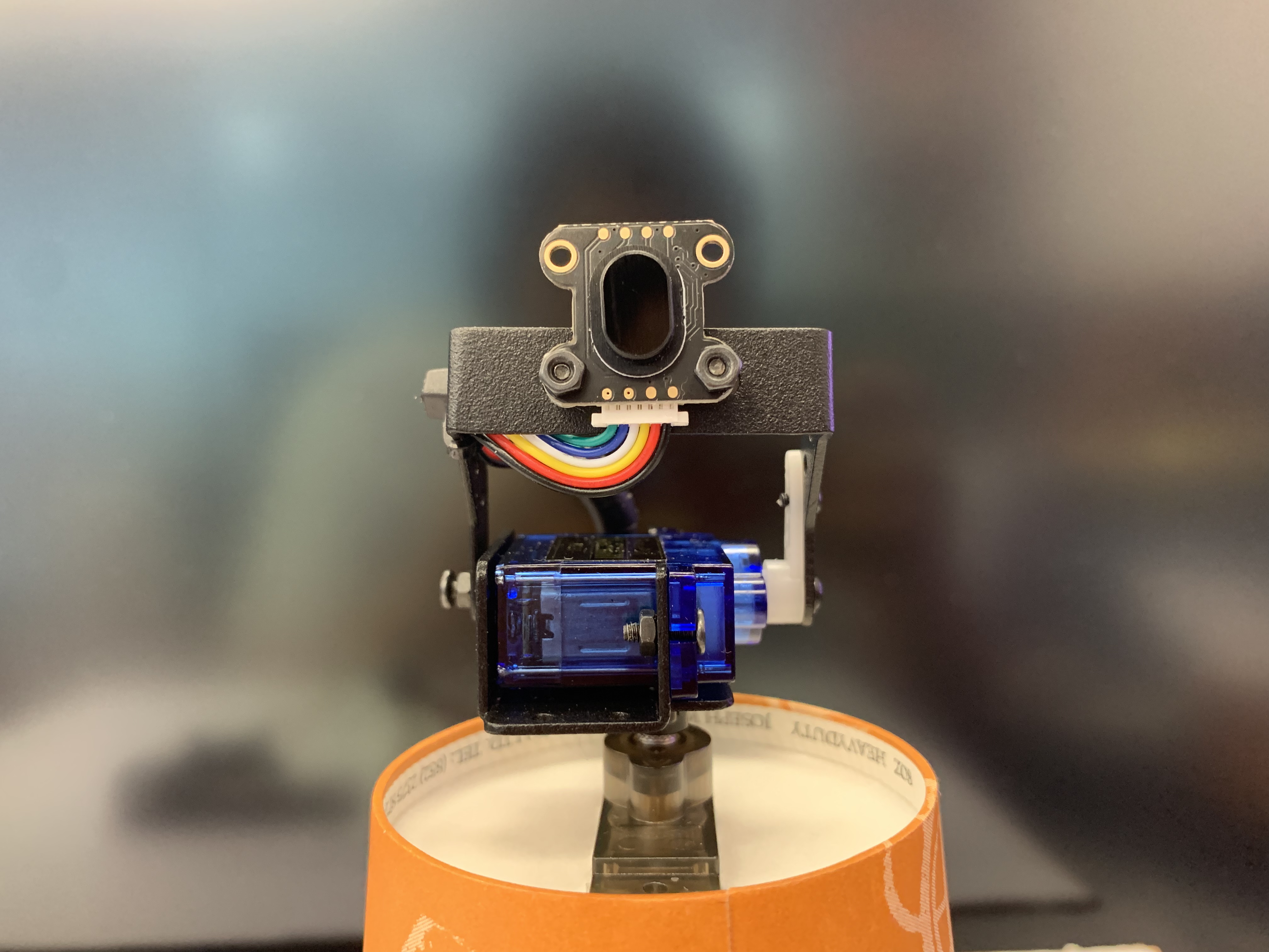
Then the first step is to determine the relative 0 degree position and relative centering angle of the device. Due to installation and Servo gear accuracy issues, the relative position angle needs to be calibrated first. After testing, the horizontal servo is exactly facing the center when set to 59 degrees (relative value 118). When the vertical Servo faces 65 degrees (relative value 130 degrees), it is exactly vertical;
  servo1.attach(SERVO_PIN1);
  servo1.write(59*2); // horizontal center position // 118
  servo2.attach(SERVO_PIN2);
  servo2.write(65*2); // vertical center position // 130
Then there is the 2-degree-of-freedom gimbal 3D scanning action in Loop(), stopping at each position of 80*60, then waiting for the TOF-400F to test the distance, and then moving to the next position after getting the data again. code show as below:
for(int i =38; i<168; i=i+4 )
    {
      servo1.write(i);
      delay(5);
      for(int m =60; m<180; m++)
      {
          while(DT.available() < 6)
          {
          }
          //Serial.print("CMD: ");
          char a = DT.read();
          if(a != 0x01)
          {
            m--;
            continue;
          }
          byte Buf[6];
          DT.readBytes(Buf, 6);
          long distance = Buf[2] * 256 + Buf[3];
          Serial.println(distance);
          servo2.write(m);
      }
      servo1.write(i+2);
      delay(5);
      for(int n=180; n>60; n--)
      {
          while(DT.available() < 6)
          {
          }
          //Serial.print("CMD: ");
          char a = DT.read();
          if(a != 0x01)
          {
            n--;
            continue;
          }
          byte Buf[6];
          DT.readBytes(Buf, 6);
          long distance = Buf[2] * 256 + Buf[3];
          servo2.write(n-1);
      }
    }
Scan the entire lattice according to the following steps, and try to avoid the servo taking repeated paths.
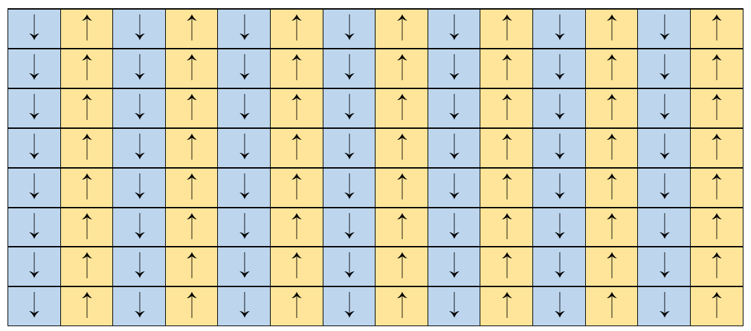
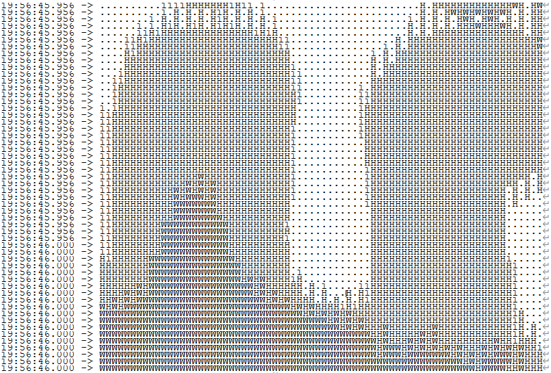
In order to observe the effect intuitively, I use characters to represent the data, and the characters represent the grading effect of the data. The code is as follows:
      for(int q = 0; q<54; q++)
      {
       for(int p = 0; p<72; p++)
       {
        if(TOF_DATA[71-p][q]>600)
        {
           Serial.print(".");
        }
        else if(TOF_DATA[71-p][q]>400)
        {
            Serial.print("1");
        }
        else if(TOF_DATA[71-p][q]>200)
        {
            Serial.print("H");
        }
        else
        {
            Serial.print("W");
        }
      }
      Serial.println("");
    }

     for(int q = 0; q<54; q++)
    {
     for(int p = 0; p<72; p++)
     {
        Serial.print(TOF_DATA[71-p][q]);
        Serial.print("mm ");
     }
    Serial.println("");
  }
The final effect is as follows:
The printed information of Arduino is as follows:
Use ChatGPT to improve the program and use more classifications.
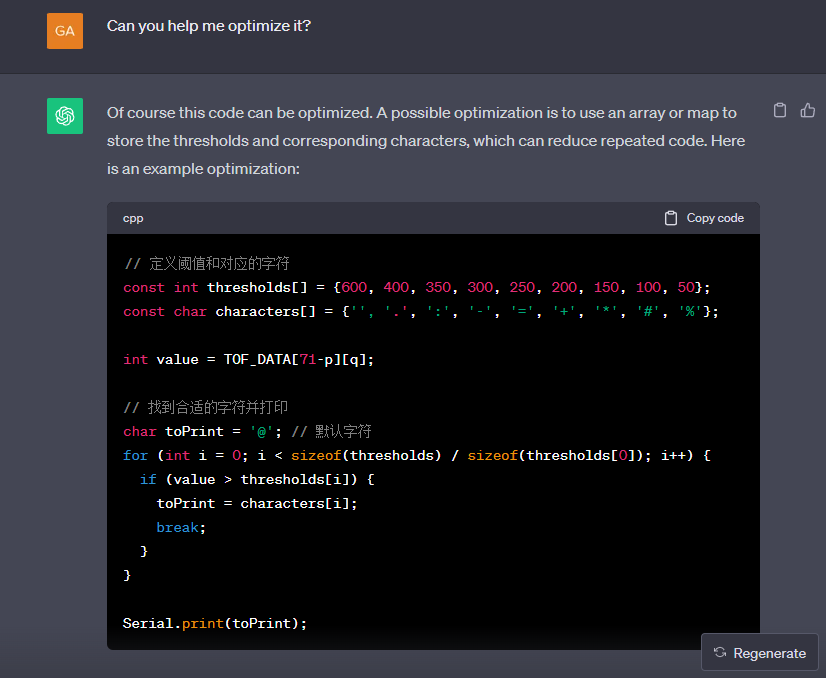
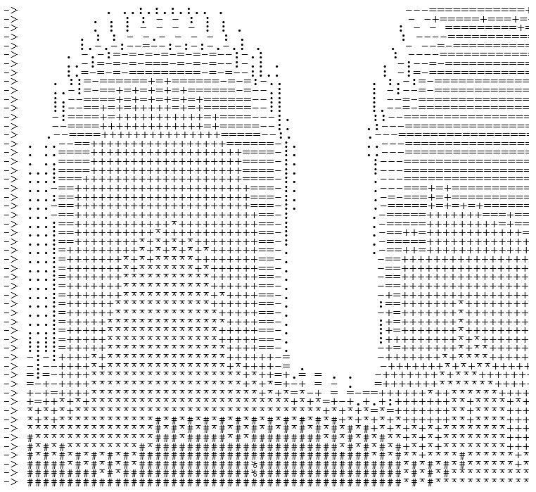
There will be more details after the improvement.
The next step is to debug the communication function.
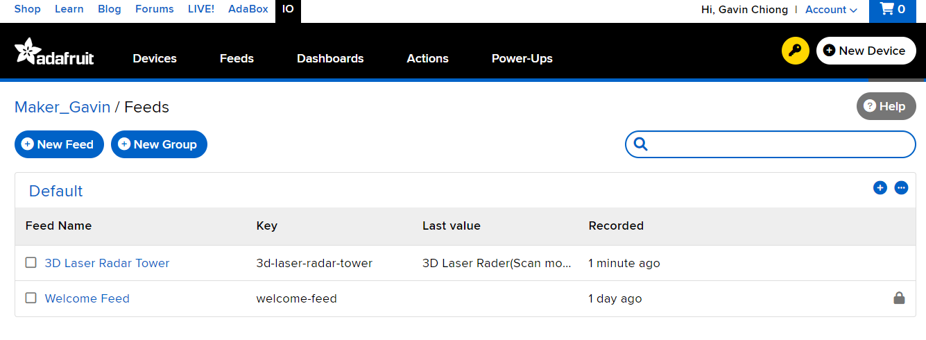
This time I used the Adafruit IO cloud to upload data, as shown below. Create a new Feed, which is the name of the data stream, and name it "3D Laser Radar Tower".
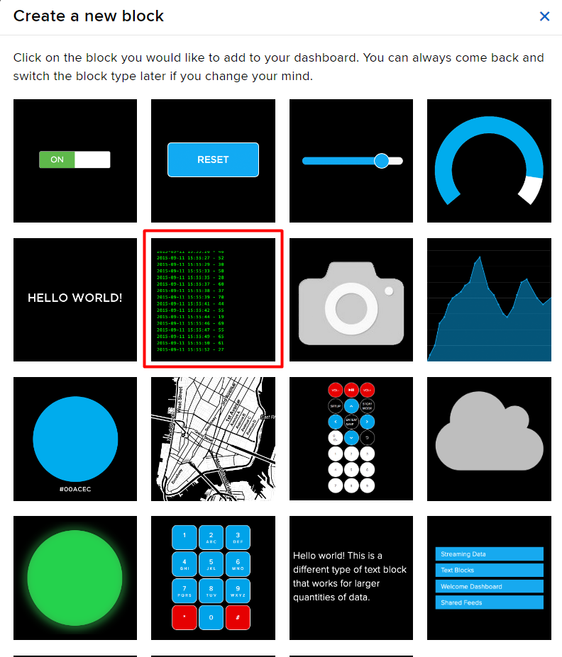
Then create a new Block in the dashboard options and select Stream as the type.
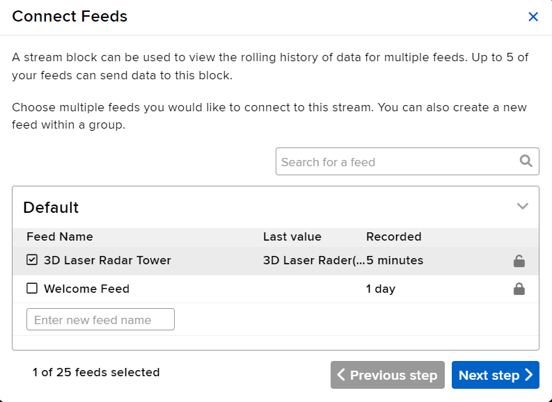
“Connect Feeds” connect this block to the "3D Laser Radar Tower" feed.
After saving and submitting, you can get the data stream from the device.
Now deal with the ARDUINO code. Add the AdafruitIO_Ethernet library.
And add IO_USERNAME and IO_KEY as shown below:
#include "AdafruitIO_Ethernet.h"
#include <SPI.h>
#include <Ethernet.h>
#define IO_USERNAME "Maker_Gavin"
#define IO_KEY "aio_be************************"
AdafruitIO_Ethernet io(IO_USERNAME, IO_KEY);
In the Setup() section, initialize the communication between the W5100S chip and Adafruit IO.
  Ethernet.init(17);  // WIZnet W5100S-EVB-Pico
  // connect to io.adafruit.com
  io.connect();

  // attach message handler for the counter feed.
  tof_feed->onMessage(handleCount);
 while(io.status() < AIO_CONNECTED) {
    Serial.print("please check Ethernet Hardware.");
    delay(500);
  }
In the Loop() section,Add Adafruit IO services. This will always run in the loop.
  // process messages and keep connection alive
  io.run();
Adafruit IO's data upload is in this format:
tof_feed->save((TOF_DATA_String.substring(q*72, (q+1)*72-1)));After I obtained the TOF data, I started to convert it into characters and uploaded it to the Adafruit IO platform. Due to the limitations of the free account, I could only transmit one frame of data every two seconds, so it took a long time to wait.
    for(int q = 0; q<54; q++)
    {
       for(int p = 0; p<72; p++)
       {
          // Find the appropriate character and print it
          char toPrint = '@'; // Default character
          for (int i = 0; i < sizeof(thresholds) / sizeof(thresholds[0]); i++) {
            if (TOF_DATA[71-p][q] > thresholds[i]) {
              toPrint = characters[i];
              break;
            }
          }
          TOF_DATA_String += toPrint;
      }
      tof_feed->save((TOF_DATA_String.substring(q*72, (q+1)*72-1)));
      delay(2000);
      Serial.println("");
    }
Then you can see the 3D Laser Radar Tower data on Adafruit IO. as follows:
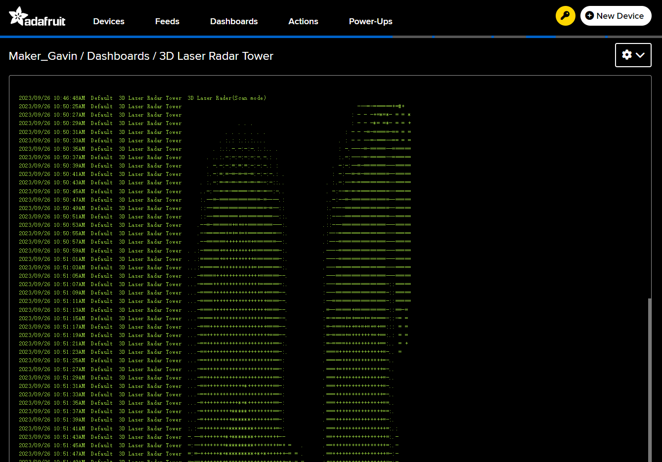
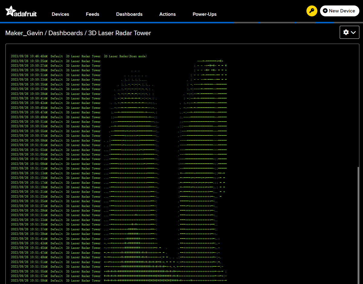
Done!
-
3D-Laser-Radar-Tower_Arduino_code
