Spi to ethernet communication.
Ethernet Chips
No replies yet. Be the first to reply.
Join the discussion.
Ethernet Chips
No replies yet. Be the first to reply.
Join the discussion.
Share projects and connect with makers.
Joined before the site update? first.
New to WIZnet Makers?
We sent a verification link to your address. Open it to activate your account, then log in.
Accounts from this email provider are reviewed by an administrator after verification. Approval usually takes one business day.
Already have an account?
Enter your email address. If it belongs to an account, we'll send a link to set a new password. Members who joined before the site update use this to set their password.
If an account uses that address, we sent a link to set a new password. The link works once and expires in 30 minutes.
Know your password?
Need an account?
RE: Spi to ethernet communication.
by irina WIZnet ·
First, please let me know what use our product name you use.
For example, just use W5500 Chip or use W5500 EVB
If you use the W5500 EVB , you just compile the project that we support project via github and download the firmware.
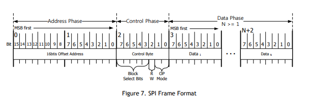
If you configure the board with W5500, you must send the data as SPI frame of W5500 from MCU.
RE: RE: Spi to ethernet communication.
by soorajsuresh80 ·
hello irina ,
thanks for the reply.
Right now i have the W5500 EVB and AOKIN ethernet network module with me .
my only aim is to get the spi data(From another MCU (tms320f28335)) over the ethernet, and monitor it through wire shark.
RE: Spi to ethernet communication.
by becky ·
The W5500’s SPI supports 80 MHz speed
What Ethernet communication do you want?
First, you should connect SPI with MCU.
And set the Source Network information .
Also set the socket communication.
please refer to 4.3.1, 4.3.2 and 4.4.1 of W5100S data sheet.
RE: RE: Spi to ethernet communication.
by soorajsuresh80 ·
Hello
Thanks becky,
let me try it out.
Can u please tell what baud rate should i use?
You said 80Mhz right? How much bits per second is 80MHz?
RE: Spi to ethernet communication.
by soorajsuresh80 ·
correct me if i am wrong, as per what i undrstood from the data sheet to establish the spi communication and get the data over the ethernet we need to send the data as per the spi frame of the W5500. And this frame is what configures the w5500 .
so that should be like this right?
first send the frame with the control bit and address phase selecting the Common register and set the ip mac and stuff there.
secondly, send other frame with address phase and control phase selecting socket register for protocol slection and all??
is that the way???
RE: Spi to ethernet communication.
by teddy ·
If you have W5500 EVB, did you execute the examples code?
and did you succeed for example code?
what’s the example code you execute?
did you configure SPI?
did you initialize w5500?
EX)
void SPI_Init()
{
}
void W5500_Init()
{
}
RE: Spi to ethernet communication.
by teddy ·
If you succeed SPI initialize or W5500 initialize, you will read VERSIONR resister.
what is VERSIONR resister value?
VERSIONR resister value must be 0x04.
RE: Spi to ethernet communication.
by irina WIZnet ·
Could you please answer me about above question?
80Mhz means SPI Clock that it send from SPI master.
Therefore, it is different with SPI baud rate and it is just SPI clock speed.
For example,
For reading the version register in W5500, it need the 32bits.
Assuming no delay between bit, the calculation is as follows.
`1/80MHz 32bits = 12.5ns32 =400ns
Even though theoretical design speed is 80MHz, the signal in the high speed may be distorted because of the circuit crosstalk and the length of the signal line. The minimum guaranteed speed of the SCLK is 33.3 MHz which was tested and measured with the stable waveform.
Please refer to the SPI Application Note which shows the WIZnet test environment and results.
RE: Spi to ethernet communication.
by soorajsuresh80 ·
this is the code i wrote for the spi communication from tms320f28335 to w5500 spi to ethernet module.
please check if the code is correct and correct me if i am wrong .
if am wrong please help me with a pseudo code for the same
//###########################################################################
#include “DSP28x_Project.h” // Device Headerfile and Examples Include File
// Prototype statements for functions found within this file.
// __interrupt void ISRTimer2(void);
typedef unsigned char uint8;
void delay_loop(void);
void spi_xmit(uint8 a);
void spi_fifo_init(void);
void spi_init(void);
void error(void);
void netwrkconfig(void);
void socketinit(void);
void portnum(void);
void opencmd(void);
void listencmd(void);
void txdata(void);
void sendcmd(void);
uint8 sdata;
void main(void)
{
// send data
//Uint16 rdata; // received data
// Step 1. Initialize System Control:
// PLL, WatchDog, enable Peripheral Clocks
InitSysCtrl();
// Step 2. Initialize GPIO:
//
InitSpiaGpio();
// Step 3. Clear all interrupts and initialize PIE vector table:
// Disable CPU interrupts
DINT;
// Initialize PIE control registers to their default state.
// The default state is all PIE interrupts disabled and flags
// are cleared.
// This function is found in the DSP2833x_PieCtrl.c file.
InitPieCtrl();
// Disable CPU interrupts and clear all CPU interrupt flags:
IER = 0x0000;
IFR = 0x0000;
// Initialize the PIE vector table with pointers to the shell Interrupt
// Service Routines (ISR).
// The shell ISR routines are found in DSP2833x_DefaultIsr.c.
// This function is found in DSP2833x_PieVect.c.
InitPieVectTable();
// Step 4. Initialize all the Device Peripherals:
// This function is found in DSP2833x_InitPeripherals.c
spi_fifo_init(); // Initialize the Spi FIFO
spi_init(); // init SPI
// Step 5. User specific code:
// Interrupts are not used in this example.
for(;
{
// Transmit data
}
}
// spi frame data functions:
//*********************************************************************************
void netwrkconfig()
{
//ip address mac SUBR SHAR SIPR are set here
}
//===========================================================================
// *****************************************
void socketinit()
{
// Sn3_MR reg
sdata = 0x0;
spi_xmit(sdata);
}
void portnum()
{
//Sn_PORT
sdata = 0x00;
spi_xmit(sdata);
}
void opencmd()
{
//Sn_CR reg
sdata = 0x00;
spi_xmit(sdata);
}
void listencmd ()
{
//Sn_CR
sdata = 0x00;
spi_xmit(sdata);
}
//*******************************************************
void txdata ()
{
sdata = 0x00;
spi_xmit(sdata);
}
//*****************************************************
void sendcmd()
{
sdata = 0x00;
spi_xmit(sdata);
}
// Step 7. Insert all local Interrupt Service Routines (ISRs) and functions here:
void delay_loop()
{
long i;
for (i = 0; i < 1000000; i++) {}
}
void error(void)
{
__asm(" ESTOP0"); // Test failed!! Stop!
for (;;);
}
void spi_init()
{
SpiaRegs.SPICCR.all =0x000F; // Reset on, rising edge, 16-bit char bits
SpiaRegs.SPICTL.all =0x0006; // Enable master mode, normal phase,
// enable talk, and SPI int disabled.
SpiaRegs.SPIBRR =0x007F;
SpiaRegs.SPICCR.all =0x009F; // Relinquish SPI from Reset
SpiaRegs.SPIPRI.bit.FREE = 1; // Set so breakpoints don’t disturb xmission
}
void spi_xmit(uint8 a)
{
SpiaRegs.SPITXBUF=a;
}
void spi_fifo_init()
{
// Initialize SPI FIFO registers
SpiaRegs.SPIFFTX.all=0xE040;
SpiaRegs.SPIFFRX.all=0x204f;
SpiaRegs.SPIFFCT.all=0x0;
}
//===========================================================================
// No more.
//===========================================================================
RE: RE: Spi to ethernet communication.
by teddy ·
hello
Why you didn’t use iolibrary for WIZNET?
why config and init functions are in the loop?
You didn’t initialize W5500.
you write wizchip_select() for CS set and reset functions.
and you write wizchip_read(), wizchip_write for SPI read& write data functions.
please, check this code.
thank you
RE: RE: Spi to ethernet communication.
by irina WIZnet ·
I think this data is 192.168.0.2 as SIPR, is it right?
If yes,where is the address of SIPR in code?
Also the ioLibrary isn’t dependent on the MCU and I don’t think you have any problem.
If you can’t use the ioLibrary, MCU should send data to W5500 SPI frame.
Further details refer to datasheet : W5500 Datasheet
RE: Spi to ethernet communication.
by soorajsuresh80 ·
Hello,
Am using the Ti’s tms320f28335 as Master . and i think no such library are available for that. If so there must a way to init and configure the w5500 right??
RE: Spi to ethernet communication.
by soorajsuresh80 ·
as the address is auto incremented for each data , i gave only the starting address of GAR. (my mistake ). as of now i changed that.
and made some more modifications in the code.
I’ll post code below please check if any changes is required.
RE: Spi to ethernet communication.
by soorajsuresh80 ·
void main(void)
{
// send data
//Uint16 rdata; // received data
// Step 1. Initialize System Control:
// PLL, WatchDog, enable Peripheral Clocks
InitSysCtrl();
// Step 2. Initialize GPIO:
//
InitSpiaGpio();
// Step 3. Clear all interrupts and initialize PIE vector table:
// Disable CPU interrupts
DINT;
// Initialize PIE control registers to their default state.
// The default state is all PIE interrupts disabled and flags
// are cleared.
// This function is found in the DSP2833x_PieCtrl.c file.
InitPieCtrl();
// Disable CPU interrupts and clear all CPU interrupt flags:
IER = 0x0000;
IFR = 0x0000;
// Initialize the PIE vector table with pointers to the shell Interrupt
// Service Routines (ISR).
// The shell ISR routines are found in DSP2833x_DefaultIsr.c.
// This function is found in DSP2833x_PieVect.c.
InitPieVectTable();
// Step 4. Initialize all the Device Peripherals:
// This function is found in DSP2833x_InitPeripherals.c
spi_fifo_init(); // Initialize the Spi FIFO
spi_init(); // init SPI
// Step 5. User specific code:
// Interrupts are not used in this example.
for(;
{
// Transmit data
GpioDataRegs.GPBCLEAR.bit.GPIO57 = 1;
MR_reg ();
GpioDataRegs.GPBCLEAR.bit.GPIO57 = 1;
}
}
// spi frame data functions:
//*********************************************************************************
void MR_reg ()
{
sdata = 0x00;
spi_xmit(sdata);
}
void GAR()
{
//ip address mac SUBR SHAR SIPR are set here
}
void SUBR()
{
}
void SHAR()
{
sdata = 0x00;
spi_xmit(sdata);
void SIPR ()
{
sdata = 0x00;
spi_xmit(sdata);
}
//===========================================================================
// *****************************************
void Sn_MR()
{
// Sn3_MR reg
sdata = 0x00;
spi_xmit(sdata);
}
void Sn_PORT()
{
sdata = 0x00;
spi_xmit(sdata);
}
void opencmd()
{
//Sn_CR reg
sdata = 0x00;
spi_xmit(sdata);
}
void Sn_DIPR()
{
//destination IP address
sdata = 0x00;
spi_xmit(sdata);
}
void Sn_DPORT()
{
//destination port number
sdata = 0x00;
spi_xmit(sdata);
}
void listencmd () // working in tcp server mode changed to TCP client mode listen chnaged to connect
{
//Sn_CR
sdata = 0x00;
spi_xmit(sdata);
}
//*******************************************************
void txdata ()
{
sdata = 0x00;
spi_xmit(sdata);
}
//*****************************************************
void sendcmd()
{
sdata = 0x00;
spi_xmit(sdata);
}
// Step 7. Insert all local Interrupt Service Routines (ISRs) and functions here:
void delay_loop()
{
long i;
for (i = 0; i < 1000000; i++) {}
}
void error(void)
{
__asm(" ESTOP0"); // Test failed!! Stop!
for (;;);
}
void spi_init()
{
SpiaRegs.SPICCR.all =0x0007; // Reset on, rising edge, 16-bit char bits
SpiaRegs.SPICTL.all =0x0006; // Enable master mode, normal phase,
// enable talk, and SPI int disabled.
SpiaRegs.SPIBRR =0x007F;
SpiaRegs.SPICCR.all =0x0097; // Relinquish SPI from Reset
SpiaRegs.SPIPRI.bit.FREE = 1; // Set so breakpoints don’t disturb xmission
}
void spi_xmit(uint8 a)
{
SpiaRegs.SPITXBUF=a;
}
void spi_fifo_init()
{
// Initialize SPI FIFO registers
SpiaRegs.SPIFFTX.all=0xE040;
SpiaRegs.SPIFFRX.all=0x204f;
SpiaRegs.SPIFFCT.all=0x0;
}