WizFi210 shield layout
Wireless
No replies yet. Be the first to reply.
Join the discussion.
Wireless
No replies yet. Be the first to reply.
Join the discussion.
Share projects and connect with makers.
Joined before the site update? first.
New to WIZnet Makers?
We sent a verification link to your address. Open it to activate your account, then log in.
Accounts from this email provider are reviewed by an administrator after verification. Approval usually takes one business day.
Already have an account?
Enter your email address. If it belongs to an account, we'll send a link to set a new password. Members who joined before the site update use this to set their password.
If an account uses that address, we sent a link to set a new password. The link works once and expires in 30 minutes.
Know your password?
Need an account?
RE: WizFi210 shield layout
by jbkim ·
ICSP에도 SPI 신호가 사용이 되고, pin 11-13에도 SPI신호가 사용이 되어서 같이 연결이 되어 있습니다.
따라서 물리적으로 연결을 끊으려면 패턴을 끊는 방법 밖에 없습니다.
RE: WizFi210 shield layout
by hornet00 ·
6핀 ICSP만 사용한다면 핀 11~13은 끊어도 된다는 것이군요. 그런데, 보드를 보니 양면으로 연결되어 있던데, ISP 선 연결이 핀 11~13하고 연결이 어떻게 되어 있나요? 단면이라 위에서 끊으면 되나요? 아래면도 보니까 연결된거 같은데… 제공해주신 회로도에서는 선 하나만 연결되어 있는 것으로 나와 있는데, 보드에서는 몇 가닥이 연결되어 있나요?
보드에서 핀 11~13을 ISP하고 연결을 끊는 방법을 알려주셨으면 합니다. 그리고, 아래 포스트 답변 부탁 드립니다. 프로그램 로딩하고 WizFi shield를 초기화 할 때, 에러가 생기는데, 뭐… reset 버튼 누르면 문제 없이 되니 괜찮은데… arduino due 보드 예제 프로그램을 부탁 드립니다. 8비트가 좀 느려서 32비트 arm으로 가야하는데, wifi 기능이 꼭 필요하거든요… 그럼, 꼭 좀 부탁드립니다.
Regards
RE: WizFi210 shield layout
by jbkim ·
첨부 그림에서 하늘색으로 표시된 부분을 컷트 하시면 됩니다.
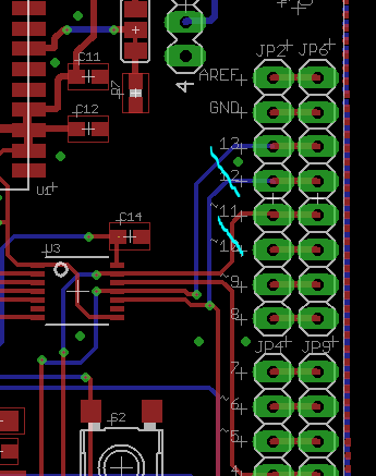
파란색 패턴은 보드의 뒷면 이고 주황색 패턴은 보드의 앞면의 패턴입니다.
RE: WizFi210 shield layout
by hornet00 ·
감사합니다.