



Microcontroller for intelligent purchase and sale of electricity in the home according to current ..
thesis builds a 1,200 CZK home energy controller where STM32F411 handles Modbus RTU to the inverter and W5500 carries PoE-powered Ethernet to a cloud MPC
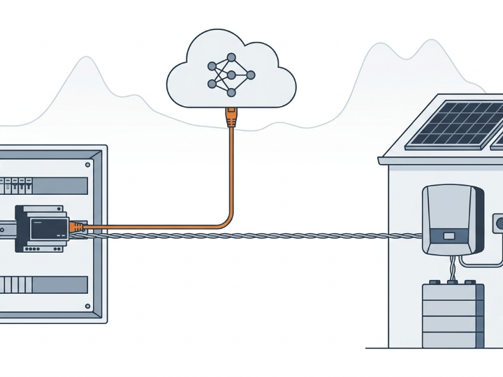
Summary (meta description) A Brno University of Technology master's thesis builds a 1,200 CZK home energy controller where STM32F411 handles Modbus RTU to the inverter and W5500 carries PoE-powered Ethernet to a cloud MPC optimizer.
COMPONENTS — Hardware components
| Component | Qty | Role in this project |
|---|---|---|
| WIZnet W5500 | x 1 | Hardwired TCP/IP Ethernet controller. SPI to STM32 at 20 MHz full-duplex, driven by ioLibrary_Driver. Socket 0 posts telemetry, Socket 1 downloads the MPC control plan. |
| STM32F411RET6TR | x 1 | Arm Cortex-M4 with FPU, 512 KB Flash. Runs the 5-second battery control loop and both communication stacks. |
| ARJM11 series RJ45 | x 1 | 10/100BASE-T modular jack with integrated magnetics, center-tap PoE extraction. |
| Texas Instruments TPS2378DDA | x 1 | PoE Powered Device controller. 25 kΩ detection signature, PoE/adapter priority arbitration. |
| Texas Instruments LMR51610YDBVR | x 1 | 1.1 MHz / 1 A buck converter for the 3.3 V and 12 V rails. |
| Texas Instruments THVD1429DT | x 1 | RS-485 transceiver with integrated TVS, for Modbus RTU to the inverter. |
| Texas Instruments ISO6731DWR + CME0303S3C | x 1 each | 3-channel digital isolator and isolated DC/DC, galvanically separating the RS-485 side. |
W5500 product page: https://docs.wiznet.io/Product/iEthernet/W5500/overview
PROJECT DESCRIPTION
📌 Overview
Czech households can buy electricity at spot prices that change every 15 minutes, and since October 2025 the Czech market publishes those prices in quarter-hour resolution. That creates a real arbitrage opportunity for any home with a photovoltaic array and a battery: charge when power is cheap, discharge when it is expensive, and never let the battery sit idle through a winter it could have been earning money in.
Vojtěch Vrzal's 2026 master's thesis at Brno University of Technology (VUT Brno), Faculty of Mechanical Engineering, supervised by Ing. Martin Appel, Ph.D., builds exactly that system — and builds it for 1,200 CZK in parts. The design is a Cloud-Edge split: a Python server runs a neural network, a consumption model, and a Model Predictive Control optimizer; a custom STM32F411 board executes the resulting plan against a SolaX hybrid inverter over Modbus RTU.
WIZnet W5500 is the bridge between those two halves, and the board takes its power from the same Ethernet cable through a PoE Powered Device stage.
The system in one line: a cloud MPC optimizer decides what the battery should do for the next 96 quarter-hours, W5500 delivers that plan to an STM32F411 over one PoE cable, and the STM32 writes a target state-of-charge into the inverter every five seconds.
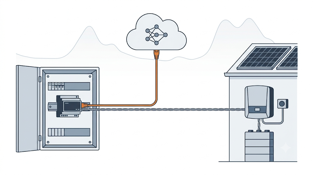
For a WIZnet reader, the interesting part is the role W5500 plays in a control system where the network is on the critical path but not in the safety path. The plan arrives over Ethernet, but if Ethernet stops, nothing breaks — the design has a deliberate, layered fallback that is worth studying on its own.
Why the Optimizer Runs in the Cloud and Not on the MCU
The thesis explicitly compares running the optimization on the server versus on the microcontroller, and chooses the server. The MPC problem is solved with CVXPY in Python over a 96-step horizon, which is not something an STM32F411 with 512 KB of Flash is going to do every 15 minutes.
That decision defines the whole architecture, and it defines W5500's job:
| Layer | Where it runs | What it does |
|---|---|---|
| Prediction and optimization | Cloud server (FastAPI, SQLite + SQLModel, CVXPY, PyTorch) | Weather fetch, PV forecast, consumption model, MPC solve, plan generation |
| Transport | W5500 + Ethernet | HTTP POST telemetry up, binary plan download |
| Execution | STM32F411 firmware | 5-second control loop, Modbus RTU writes, safety fallback |
| Actuation | SolaX hybrid inverter | Internal current regulation, MPPT, battery management |
The firmware is organized in three layers that mirror this: an application layer (app_main, system_state), a communication layer (server_comm, inverter_comm), and a driver layer consisting of STM32 HAL plus WIZnet ioLibrary. The communication modules make no control decisions — they only translate application requests into protocol telegrams. A shared SystemState_t structure acts as the single source of truth.
The W5500 Network Path
Two sockets, two directions, two formats
The STM32 talks to W5500 over SPI in full-duplex at 20 MHz, using ioLibrary_Driver for its BSD-sockets-style abstraction over the chip's registers. The design allocates two dedicated hardware sockets rather than multiplexing one:
| Socket | Direction | Method | Payload format |
|---|---|---|---|
| Socket 0 | MCU → Server | HTTP POST | JSON telemetry |
| Socket 1 | Server → MCU | HTTP GET | Custom binary plan |
The asymmetry is intentional and well argued in the thesis. Telemetry goes up as JSON because the server side archives it, feeds it into model retraining, and benefits from human-readable logs. The control plan comes down as raw binary because the MCU has to parse it, and the thesis measured JSON as carrying very high metadata overhead and high MCU parsing cost compared to a C-struct layout that maps directly into RAM by pointer.
The "ACTN" plan packet
The downlink protocol is a small, well-specified binary format worth copying:
Header:  "ACTN"  (4-byte magic word)
         protocol version
         UNIX timestamp
         record count
         CRC16 (Modbus polynomial)

Record:  6 bytes each
         - 15-minute interval index (0–95)
         - target battery SOC
         - relay mask
         - requested appliance power
         - CRC16 (Modbus polynomial)
Every record carries its own CRC16 in addition to the header CRC, so a corrupted record can be rejected without discarding the whole day's plan. Given that this arrives over TCP — which already guarantees delivery integrity end to end — the per-record CRC is defense against corruption anywhere in the chain, not just on the wire.
Telemetry that has already been filtered
The MCU does not send raw samples. It reads inverter SOC and instantaneous power every Ts = 5 s into accumulators inside SystemState_t (int32 for power to avoid overflow across 60 samples at tens of kW, float for SOC), then transmits the arithmetic mean every Ttel = 5 min — exactly 60 samples per window.
This is a low-pass filter implemented at the point of measurement, and the thesis is explicit about why: appliance inrush spikes are artifacts for energy planning, and the LSTM models trained later on this data need clean, evenly spaced series. It also keeps the data rate low enough that the Ethernet link is never the bottleneck.
Security
The FastAPI server authorizes at the HTTP header level. Each registered user gets a cryptographically generated 32-character hexadecimal key, and the MCU attaches it to every request in an X-API-Key header. The thesis notes this was chosen over JWT specifically because token parsing is expensive on a hardware-limited microcontroller, while adding one header field costs essentially nothing.
The PoE Power Path
The reason for PoE here is installation, not novelty: the controller lives in a home distribution cabinet, and one cable for data and power is dramatically easier to run than two.
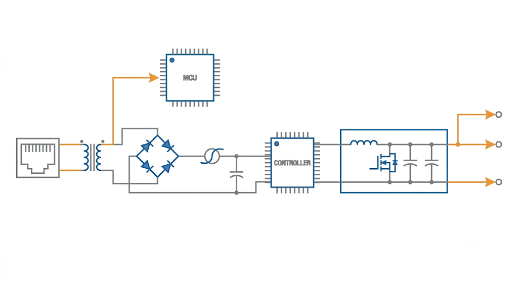
The implementation is a clean, textbook PD front end:
- Center-tap extraction. The ARJM11-series RJ45 jack has integrated magnetics rated for IEEE 802.3af/at/bt. DC injected as common-mode voltage on the twisted pairs is taken from the transformer center taps.
- Bob Smith termination. Unused pairs are terminated through 75 Ω resistors and a common capacitor to ground — an EMI and impedance-matching measure the thesis calls out explicitly as important for EMC compliance.
- Polarity-agnostic rectification. Because PoE injectors may present either polarity (MDI vs MDI-X), the input goes through diode bridges before the PD controller.
- Filtering and protection. An LC filter with ferrite beads smooths the rail; an SMAJ58 TVS diode handles surge and ESD.
- PD controller. The TPS2378DDA presents the 25 kΩ detection signature the powered-source equipment looks for, and connects PoE ground to board ground once detection succeeds. A 1 Ω series resistor limits inrush into the ceramic output capacitors.
- Source arbitration. The controller automatically handles priority between PoE and an external DC adapter via its APD pin, so the unit can be bench-powered during commissioning and PoE-powered in the field without a jumper.
Downstream, an LMR51610YDBVR buck at 1.1 MHz produces the 3.3 V rail feeding the STM32, W5500, and peripherals, plus a 12 V rail for MOSFET drivers.
Design lesson: W5500 does not do PoE. The two live on the same connector and cooperate, but the PD controller, magnetics, bridges, and protection are entirely separate circuitry. This is one of the most common misunderstandings about "PoE Ethernet chips," and this thesis lays out the separation cleanly enough to use as a teaching schematic.
W5500 Schematic and Layout Details
The thesis documents the W5500 support circuitry at a level most maker projects skip, and these are the numbers people most often get wrong on a first Ethernet board:
| Item | Value in this design |
|---|---|
| MCU interface | SPI on PA5 / PA6 / PA7; control and interrupt signals (nRESET, nSCS, nINT) on PB0, PB1, PB2, PC4, PC5, PA2 |
| Reference clock | 25 MHz crystal, 18 pF load capacitance |
| Crystal load caps | C1, C2 = 30 pF |
| Crystal series resistor | R2 = 33 Ω, determined empirically for reliable oscillator startup |
| Crystal parallel resistor | R1 = 1 MΩ |
| Receive path matching | 49.9 Ω resistors with 6.8 nF capacitors |
| Signal integrity | 33 Ω series resistors on all communication lines to suppress reflections |
| Analog supply | Dedicated power polygon for the W5500 analog rail |
| Connector isolation | USB-C and RJ45 shields tied to board ground through 1 MΩ resistors in parallel with capacitors |
The RS-485 section is fully isolated in both signal and supply domains — digital isolator plus isolated DC/DC — specifically to prevent ground loops between the control cabinet and the inverter. A separate 12 V polygon is carved out in the PWM output region.
For anyone laying out a W5500 board for the first time, that table is close to a checklist.
Firmware: Fast Loop, and What Happens When the Network Dies
This is the part of the project most worth reading for anyone building networked control hardware.
The control loop runs deterministically at 5 s. Using an RTC-maintained UNIX timestamp, the firmware determines which of the day's 96 quarter-hour slots (index 0–95) is currently valid and pulls the corresponding target SOC from the downloaded plan.
Rather than crude on/off switching, it uses the inverter's native capacity-targeting interface over Modbus RTU:
| Register | Purpose | Value written |
|---|---|---|
0x007C ModbusPowerControl | Remote control mode | 3 = enable SOC target control; 0 = disable |
0x0083 TargetSoc | Target state of charge | From the current 15-minute plan slot |
0x0088 RemoteCtrlTimeOut | Inverter-side communication watchdog | 30 seconds, written periodically |
Low-level current regulation and power flow direction stay inside the inverter's own fast algorithms, which the thesis argues improves overall system stability — the STM32 sets the goal, the inverter figures out how to reach it.
Three independent fallback layers protect the household:
- Plan expiry. If the downloaded plan has aged out, the firmware writes
0to0x007Cand the inverter reverts to its factory Self-use mode. - Network failure. If server communication fails, the same thing happens — remote control is dropped deliberately rather than continuing on stale data.
- Controller failure. The
RemoteCtrlTimeOutwatchdog lives inside the inverter. If the STM32 crashes or the RS-485 cable is cut, the inverter cancels remote control after 30 seconds on its own.
The third layer is the important one. It means no software or hardware fault in the WIZnet-connected controller can leave the inverter stuck in an unwanted state such as continuous forced discharge to the grid. The verification chapter tested this by physically unplugging the RS-485 cable during active remote control, and confirmed the inverter fell back to Self-use after the 30-second limit.
For W5500 developers: this is a good template for any Ethernet-connected controller. Design so that losing the network is a normal, tested state rather than an exception, and put the final safety timeout in the device being controlled rather than in the controller.
What the Cloud Side Does With the Data
The prediction stack is worth summarizing because it explains why the telemetry format matters.
PV production forecast — a feedforward neural network in PyTorch. After testing candidate meteorological inputs for predictive value and low mutual correlation, six were selected: cosine of the solar incidence angle, solar elevation, sunshine duration, low cloud cover, total cloud cover, and ambient temperature. The architecture is three fully connected hidden layers of 128 – 64 – 32 with ReLU, Dropout 0.2, Adam at a learning rate of 0.0005, MAE loss, and MinMax input normalization. Training used roughly 84,000 hourly records split 80/20, over 100 epochs.
Then it gets personalized. A global model turned out to be insufficient because real installations differ in panel age and degradation, local shading from buildings and vegetation, and installation deviations from the documented tilt and azimuth. The most striking failure mode: on systems with export limitation, the global model predicts the physical maximum while the real inverter is being curtailed to zero at midday. The solution is transfer learning — take the global weights and fine-tune on each roof's own data.
Consumption forecast uses a statistical model with quadratic polynomial coefficients stored per user, adjusted by outdoor temperature and day type.
External data comes from Open-Meteo for weather and spotovaelektrina.cz for Czech spot prices in CZK/MWh.
The MPC objective function is more nuanced than pure price arbitrage. It includes distribution fees and taxes, the trader's buyback fee, battery cyclic wear cost per kWh, penalty weights for high state of charge, and penalty weights for indoor and hot-water temperature deviation. Including wear cost is why the algorithm sometimes declines to trade at all — if the price spread does not cover degradation plus round-trip conversion losses, doing nothing is optimal.
Results: Does the Arbitrage Actually Pay?
The evaluation used real operational data from 1 October 2025 to 30 April 2026 — chosen because Czech spot prices moved to quarter-hour resolution in October 2025 — simulated across 20,253 quarter-hour steps with a 10.0 kWh battery.
| Scenario | Total cost over the period |
|---|---|
| Fixed tariff, no PV or battery (baseline) | 63,136 CZK |
| Spot tariff, no PV or battery | 54,182 CZK |
| Fixed tariff, with PV and standard battery control | 59,950 CZK |
| Spot tariff, with PV and standard battery control | 52,080 CZK |
| Spot tariff, with PV and the proposed MPC control | 51,455 CZK |
Read honestly, and the thesis reads it honestly:
- Most of the saving comes from the tariff, not the algorithm. Moving to spot pricing was worth roughly 9,000 CZK over the winter half-year.
- Total saving from MPC versus the baseline was 11,681 CZK.
- The algorithm's own net contribution — MPC versus standard battery control on the same spot tariff — was 625 CZK.
- Adding a conventionally controlled PV and battery to a fixed tariff saved only 625 CZK, because in winter a battery with no arbitrage capability mostly sits unused.
That 625 CZK figure is the number that matters, and it is where the hardware cost becomes the point. The controller costs 1,200 CZK to build — 400 CZK for the PCB, 800 CZK for components. A 625 CZK net gain across a single winter half-year against a 1,200 CZK build cost gives an estimated payback of one to two years, before counting summer, when surplus generation and larger price spreads should make arbitrage considerably more profitable.
Verification of the Ethernet Path
The hardware bring-up chapter documents the W5500 path specifically:
- The buck stage was verified to deliver a stable 3.3 V to the STM32, W5500, and peripherals, and 12 V to the MOSFET drivers, before the ICs were trusted.
- Galvanic isolation between the digital section and the RS-485 driver was confirmed with a multimeter.
- Through W5500 and its integrated TCP/IP stack, a stable network connection to the local LAN was established, HTTP communication was initialized, and the first test telemetry packet reached the remote server — verified against the server log.
- On the inverter side, Modbus RTU successfully read live PV power and battery SOC, and a write to
0x007Cconfirmed the controller could change inverter modes in real time.
That last pairing is the whole system in miniature: read from the inverter, average, ship over W5500, receive a plan, write back to the inverter.
What a Developer Can Reuse
- The two-socket pattern. Dedicating Socket 0 to uplink and Socket 1 to downlink, rather than opening and closing one socket per transaction, avoids handshake churn and keeps the two data paths independent. W5500's eight hardware sockets make this free.
- Asymmetric serialization. JSON up, binary down. Optimize each direction for whichever side has to parse it. This is a better default than picking one format for the whole system.
- The magic word + CRC16 record format.
"ACTN"plus per-record CRC is a small, robust plan-download protocol that any scheduled-control device could adopt. - Edge-side averaging before transmission. 60 samples in, one telemetry point out. Reduces bandwidth, database volume, and — importantly — improves downstream model convergence.
- The complete PoE PD front end. Bob Smith termination, polarity bridges, TVS, PD controller with inrush limiting and adapter arbitration. It is a reusable reference block.
- The W5500 crystal and matching values. 25 MHz / 18 pF, 30 pF load caps, 33 Ω series, 1 MΩ parallel, 49.9 Ω + 6.8 nF on receive.
Limitations to note. The design is tied to SolaX inverter register semantics; adapting it to another manufacturer means rewriting inverter_comm. Transport security beyond the API key is not addressed. And the economic case is validated only over a winter half-year — the summer figures that would strengthen it are projected rather than measured.
Why This Is a Good W5500 Design Case
Home energy management is exactly the kind of application where the network's job is easy to misdescribe. It is tempting to call the Ethernet link "the smart part" because that is where the AI lives. It is not. The intelligence is in the cloud; the safety is in the inverter; the real-time determinism is in the STM32's 5-second loop.
W5500's contribution is that none of those three had to compromise for the network to exist. The STM32 kept its Flash and its cycles because there is no software TCP/IP stack. The plan arrives reliably because TCP is handled in hardware. The installation is one cable because PoE and Ethernet share a connector. And when the link goes down, the system degrades to a safe, tested state instead of failing.
For 1,200 CZK in parts, that is a strong argument for hardwired TCP/IP in cost-sensitive control hardware — and a reminder that the most valuable network component in a control system is often the one that is completely uneventful.
Related WIZnet Maker Projects
- Smart Home Energy Management Controller with the Waveshare ESP32-S3-POE-ETH — the closest functional companion: home energy management over PoE Ethernet, built on a commercial module instead of a custom PCB.
- How to Log Growatt Solar Inverter Data with W5500 on ESP32 — the read-only half of this architecture: inverter telemetry to the network via W5500.
- Modbus RTU-to-TCP Gateway with W5500 and STM32 — the same RS-485-plus-W5500-on-STM32 hardware pattern, packaged as a general-purpose gateway.
- Introduction to Ethernet and Wi-Fi to Modbus Conversion Using STM32F411 and W5500 — the identical MCU and Ethernet controller pairing, useful as a starting point for the port layer.
- OpenDTU-OnBattery — open-source PV and battery monitoring with Ethernet, for comparison of the data model.
Source-Backed Summary
Vojtěch Vrzal's 2026 master's thesis at Brno University of Technology designs and builds a low-cost home energy management controller that minimizes electricity cost by trading against 15-minute spot prices. A cloud server running FastAPI, a PyTorch PV-forecast network, and a CVXPY-based MPC optimizer produces a 96-slot daily plan; a custom STM32F411RET6 board downloads that plan through WIZnet W5500 and executes it against a SolaX hybrid inverter over isolated RS-485 Modbus RTU, drawing its own power from the same Ethernet cable via a TPS2378 PoE PD stage.
W5500 runs on SPI at 20 MHz with ioLibrary_Driver, using Socket 0 for JSON telemetry over HTTP POST and Socket 1 for a CRC16-protected binary plan download over HTTP GET. Bring-up testing confirmed the full path from board power rails through the first telemetry packet reaching the server log. Simulation over 20,253 quarter-hour steps from October 2025 to April 2026 showed total costs of 51,455 CZK with MPC against a 63,136 CZK fixed-tariff baseline, with the algorithm's own net contribution at 625 CZK against a 1,200 CZK hardware cost.
For WIZnet developers, the value is a complete, documented reference design: PoE PD front end, W5500 crystal and matching values, a two-socket communication pattern, an asymmetric JSON-up / binary-down protocol, and a layered network-failure fallback that ends inside the controlled device rather than the controller.
❓ FAQ
Q. Does W5500 handle the PoE power conversion? No. W5500 handles Ethernet communication only. Power extraction is done at the RJ45 magnetics center taps and converted by a separate chain: diode bridges, LC filter, TVS, the TPS2378DDA PD controller, and an LMR51610 buck converter.
Q. Does the design use MACRAW mode or a software TCP/IP stack? Neither. It uses W5500's hardwired TCP/IP stack through ioLibrary_Driver's BSD-sockets-style API. There is no lwIP in the firmware — that is precisely why an STM32F411 has room for the rest of the application.
Q. Why two sockets instead of one? Socket 0 is dedicated to uplink telemetry (HTTP POST, JSON) and Socket 1 to downlink plan retrieval (HTTP GET, binary). Keeping them separate avoids reopening sockets per transaction and keeps the two data flows independent. W5500 provides eight hardware sockets, so this costs nothing.
Q. What happens if the Ethernet link goes down? Three layers of fallback. The firmware drops remote control when the plan expires or the server is unreachable. Independently, the inverter's own RemoteCtrlTimeOut watchdog cancels remote control 30 seconds after the last valid Modbus packet, so even a total controller failure returns the household to the inverter's autonomous Self-use mode. This was verified by physically disconnecting the cable during operation.
Q. Why send JSON one way and binary the other? Because different sides do the parsing. The server archives telemetry and retrains models, so human-readable JSON is convenient there. The MCU parses the control plan, so a fixed binary layout that maps directly into RAM is far cheaper than tokenizing text.