Arduino Based Smart Home IOT System
Arduino Based Smart Home IOT System
0
Components
Hardware components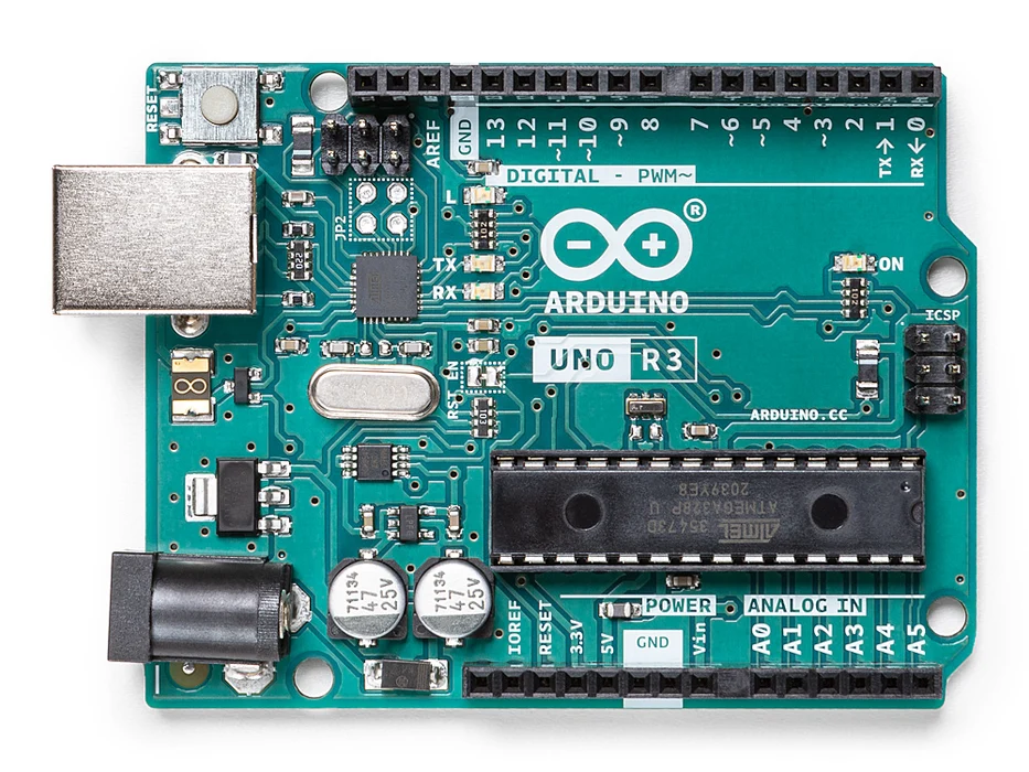
Arduino - Arduino UNO
x 1

Ethernet module (or shield) (based on W5100 chip ! important !)*
x 1
Shift Register IC - 74HC595
x 1
8x buttons
x 1
8x 220 Ohm, 2x 1K, 2x 2K, 2x 3K, 3x 10K, 1x 100K resistors
x 1
1x photocell
x 1
Breadboard
x 1
Some breadboard cables
x 1
8x screw drivers for outputs, 2x for power output and 2x for photocell
x 1
LD1117V33 Voltage regulator (3.3V output)
x 1
Project description
Step 1: Shift Register 595 and Outputs The shift register will give to your Arduino an additional 8 digital outputs, by using only 3 pins on your board! Here you can find a simple tutorial with the shift register 595 IC and Arduino uno board. SR 595 and Arduino uno: Pin 8 (GND) to GND Pin 10 (SRCLR') to 5V Pin 11 (SRCLK) to Arduino pin 6 Pin 12 (RCLK) to Arduino pin 5 Pin 13 (OE') to GND Pin 14 (SER) to Arduino pin 4 Pin 16 (Vcc) to 5V QA is the first output - QH is the 8th output. We will connect each output with one screw driver - terminal and with an LED through a 220 Ohm resistor. When…
Keep reading with a free account
Guests can read 15 projects per visit. Log in or create a free account to read the full description, open the documents and join the comments.