
WIZnet ISS Notifier
A desktop light design to give a visual indication of how far away the International Space Station is, and to alert when it is visible.
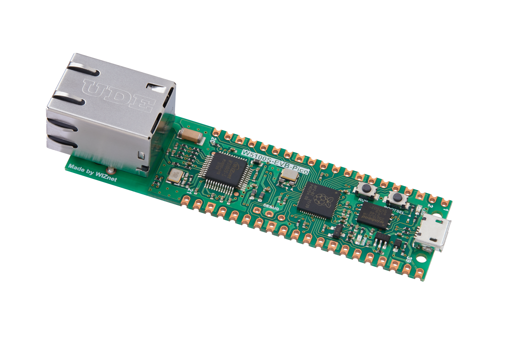
WIZnet - W5100S-EVB-Pico
x 1
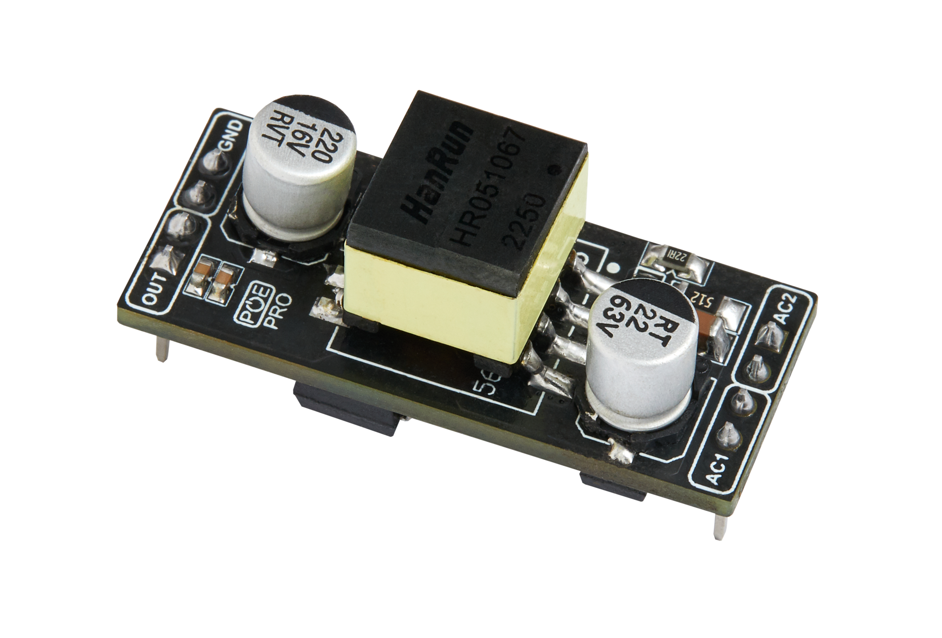
WIZnet - WIZPoE-P1
x 1

DFRobot - WS2812B LED Strip
x 1
Any bair "neopixel compatible" LED strip will work.
thonny.org - Thonny
x 1
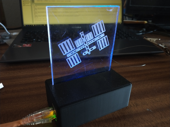
The WIZnet ISS Notifier is a desktop light designed to give a visual indication of how far away the International Space Station is, and to alert us when it is going to be passing.
The concept is not new and various versions have been done of this over the years. The unique element of this design is that it is PoE powered and easily moddable in Micropython. If you do use this as a base of your project then please do share that.
What is Needed
The hardware element of the project is very easy to construct. Full instructions are below and hardware requirements are above. The only thing not listed is a short length of wire to collect the LED strip, and a network cable that can plug you into a PoE switch.
The case design is ready to be 3D printed. You will not need any supports with the design. The light up part is acrylic and is best cut and etched on a laser cutter.
Installing MicroPython
Before we can upload our firmware we need to install Micropython.
To do this download the compiled MicroPythonbinary ZIP file from https://github.com/WIZnet-ioNIC/WIZnet-ioNIC-micropython/releases and extract its contents. Then plug in the W55RP20-EVB-Pico to your computer using a USB cable while pressing the button closest to the USB connector. Your computer will then install some drivers and a virtual disk drive will become available. Copy the file “firmware.uf2” that you expected before on to the virtual disk, the drive will vanish as it reboots, and then your board is running MicroPython.
Setting up Thony
To keep things simple we are going to use Thony to modify and transfer the firmware. This can be downloaded from https://thonny.org/ . The only configuration that will be needed it to select “Options” from the “Tools” menu, select the “Interpreter” tab, and then change the interpreter to “MicroPython (RP2040)”. Click the “Stop” icon on the toolbar and you should get the message like “MicroPython 3ca01ecca-dirty on 2024-09-10; W55RP20-EVB-Pico with RP2040” in the shell part of the screen.
Uploading the firmware
Before we can upload our firmware we need to install the Neopixel library created by Blaž Rolih. This library can be downloaded from https://github.com/blaz-r/pi_pico_neopixel/blob/main/neopixel.py and the process of copying it to the hardware is documented on the library wiki.
Now we need to save our code to the WizNET ioNIC and we will use the same technique. In Thony click the “New” icon on the toolbar (the sheet of blank paper to the left), copy the firmware from this page, and then paste it into the new document we just created. The only setting that needs changes is our location towards the top of the script (line 15 and 16). To get these numbers find your location on Google Map, right click on that location, and select the coordinates that will be in the pop up menu.
To save it click the “Save” icon on the toolbar (the retro floppy sick icon that will likely be the third icon in from the left), press the “RP2040 device” button, and enter a name for the new file. We will call the file “main.py” so it will start when we power on the device. For testing you can call it whatever you want, but remember to add the “.py” to the end.
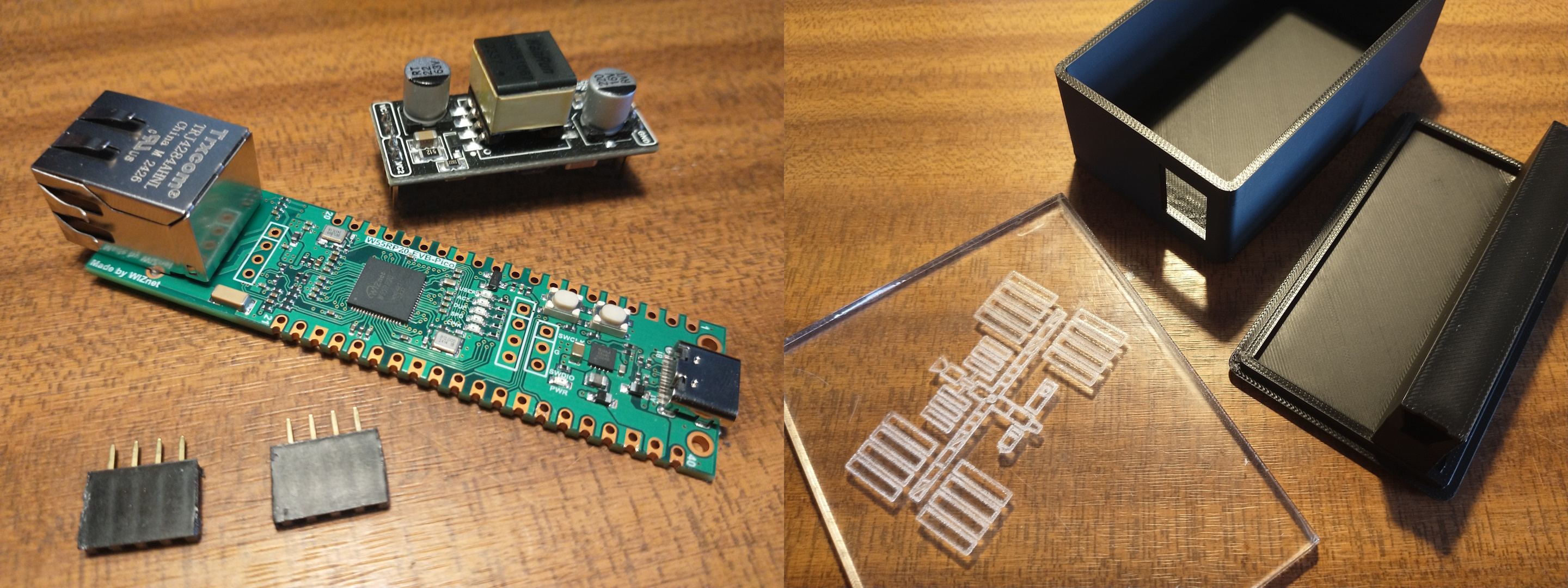
Assembling the electronics
The electronics are simple and the only soldering we only need to do is to add the header socket for the PoE adapter (often included with the adapter) and to connect the addressable LED strip to the board. If you can not solder then there are many great tutorials online.
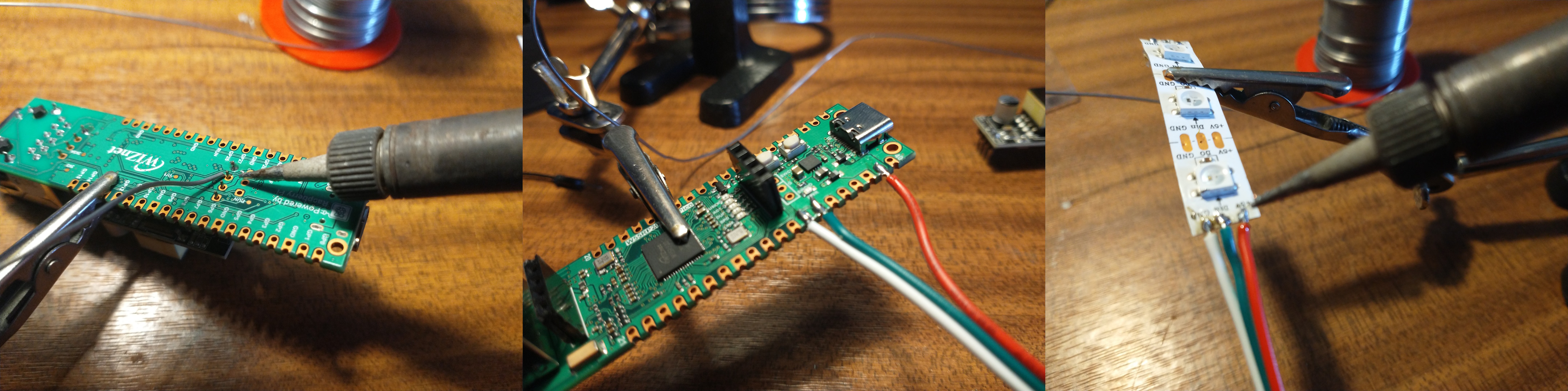
First solder on the header socket for the PoE adapter. I find it easier to plug them on to the adapter itself to hold them in place, solder one of the pins to hold it steady, and then solder the rest after removing the adapter.
The wires are even easier to attach. We need to attach GND and GND, GP23 (pin 34) to Din, and VSYS (pin 39) to +5v. It is worth noting that the GND connectors are more square and this can help identify the correct pads to solder without needing to turn over the board.
Assembling the case
This is again very simple and easy. The board’s Ethernet connector should fit thought the hole at the side, and the board be generally pushed down until it is supported by a raised support.
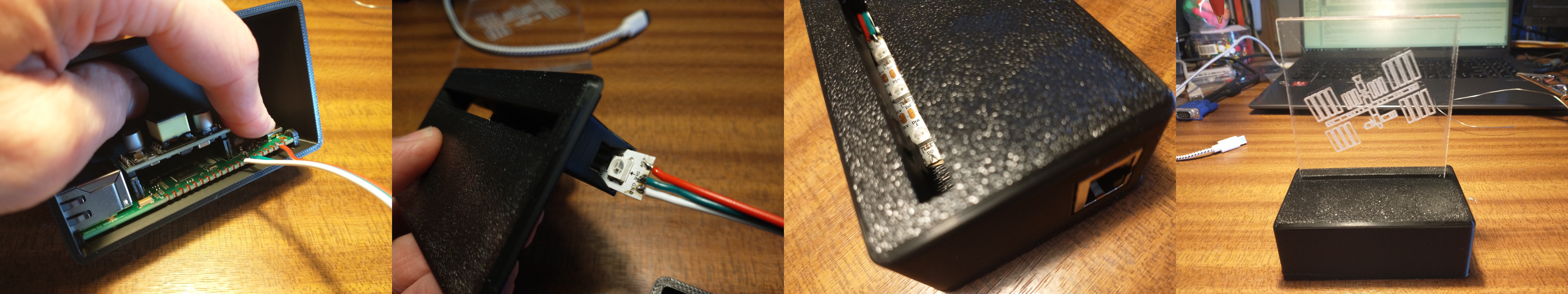
The LED strip should slide into the gap in the case top. When it is in the correct position I find it useful to fold the wires round the end of the plastic to help keep it in place.
After that simply put the two halves together and insert the acrylic sheet into slot.
Demonstration
This is a demonstration of the WIZnet ISS Notifier in Action. As the ISS was not passing my location so I pretended I was just South of Santiago, Chile (where the red arrow is pointing to on the screen).
The action starts at 8 minutes into the video, but feel free to watch from power to after the ISS has passed.
-
Case (bottom part)
This is printed in PLA on any FDM printer. It should not require any supports or custom settings.

-
Case (top part)
This is printed upside down in PLA on any FDM printer. It should not require any supports or custom settings.
-
Wiring Diagram
-
Light up insert
Laser cut the vector lines from a 4mm or 5mm sheet of acrylic, and engrave the bitmap.
-
Main Firmware