Web App RGB LED Controller with WIZ750SR and Zynq FPGA
Add Ethernet connectivity to an FPGA with the WIZ750SR module. Control RGB LEDs via a Python Flask web app from your browser.
0
Components
Hardware components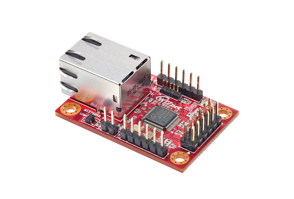
WIZnet - WIZ750SR
x 1

Vivado - Xilinx Vivado toolkit
x 1
Project description
Story
Introduction
This project will demonstrate how to control an FPGA via your browser by adding Ethernet connectivity using the WIZ750SR serial to Ethernet bridge. The idea is to use the module to enable Ethernet communication to a MiniZed Zynq board by implementing a UART serial controller working alongside the ARM CPU core. The FPGA in turn controls RGB LEDs based on the serial commands it receives.
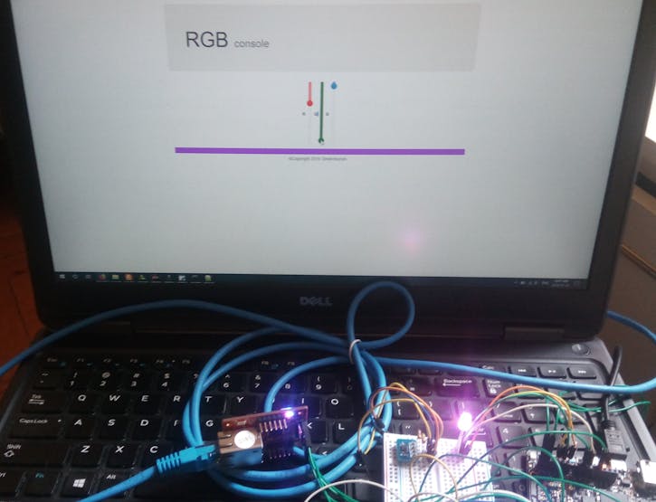
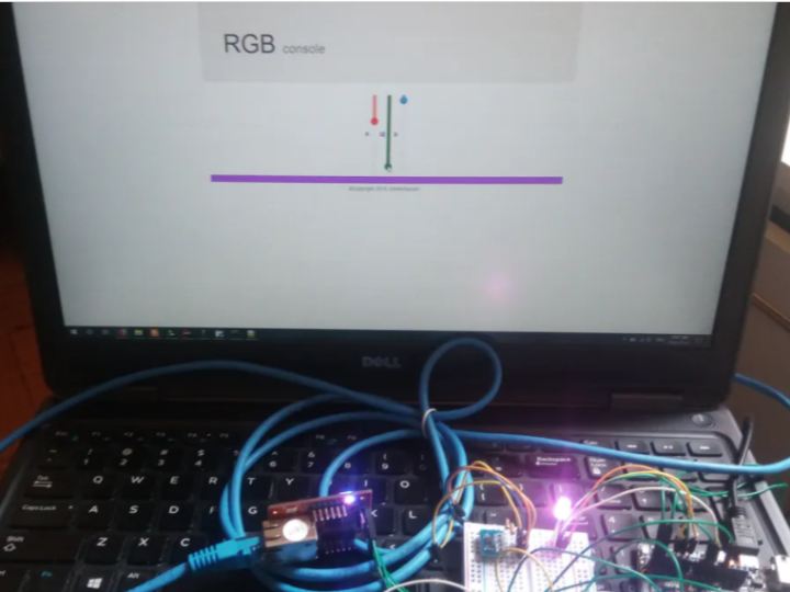
The hardware consists of the WIZ750SR serial to Ethernet module and the MiniZed FPGA board together with an RGB LED. This development board is connected to a diffused RGB LEDs which will be controlled via a Python Flask web app.
Configuring the S2E Bridge
The main component is the WIZ750SR module. This module takes care of the translation between the TCP or UDP protocols to and from the serial protocol.
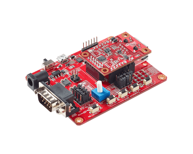
After unboxing the unit. I removed the unit from the baseboard and connected a CAT5 cable between the module and the laptop. The VDD and GND pins were connected to 3.3v and GND respectively. The blue LED turned on which indicated that a connection was made. Next I reconfigured the Ethernet port and used the configuration tool to search the module and configure it as a TCP server.
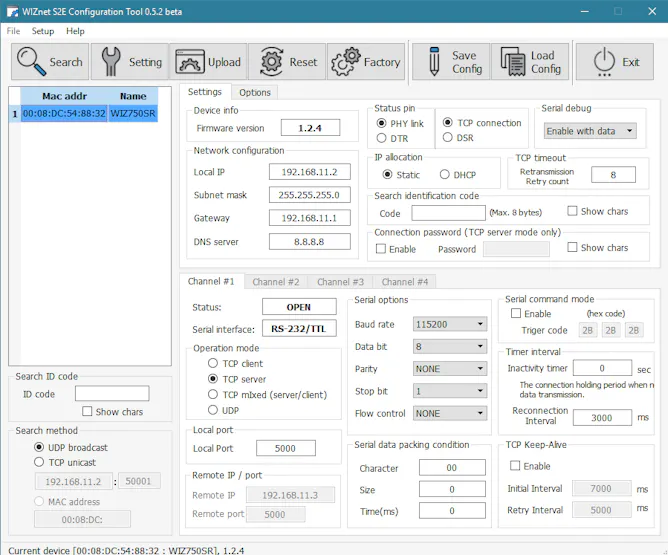
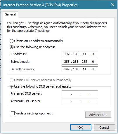
The latest FW version by Wiznet had been upgraded to 1.2.4 so I used the utility to upgrade the FW, Next step was configuring the Ethernet IP adapter IP with the remote IP address.
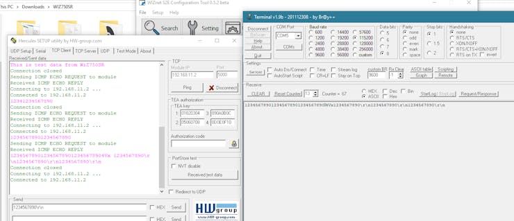
After that was done, a UART to USB bridge was connected to the TXD, RXD VDD, and GND pins of the module and tested communication in both directions. Lo and behold it worked like a charm.
Building the Web App
Next step was coding the web app. To test the app one has to install Python Flask by issuing:
pip install flask
This will pull all the dependencies. The app serves a webpage with three sliders. One for each LED. The RGB data from the Flask server is received as JSON packets. These data are parsed and the slider values are sent via TCP client socket connections to the WIZNET module which is configured as a TCP server. After I finalized the app I tested it by issuing the command:
python app.py
Then open a web-browser and navigate to localhost port 5000. \localhost:5000. The RGB data from the Flask server is received as JSON packets. These are parsed and sent via TCP sockets to the WIZNET module.
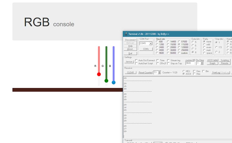
To set the communication I enabled the debug printf on Zynq This serial connection uses the PS UART1 of the ARM MPU. After verifying that the data was correct the program on the Zynq side was augmented by converting the received strings into numbers that range from 0-255.
Zynq FPGA SoC Configuration
Zynq Hardware
The MiniZed is a Zynq FPGA SoC that has an Arduino form factor so the connection between the serial pins of the wiz750sr Ethernet module and the dev-board has been kept the same. Pins RXD and TXD are pins 0 and 1 of the Arduino connector
The first step is to enable the Zynq processor to connect to FPGA fabric cores. The master AXI bus has to be enabled so after clicking on the Zynq processor block under the PL-PS configuration the GP Master interface has to be enabled.
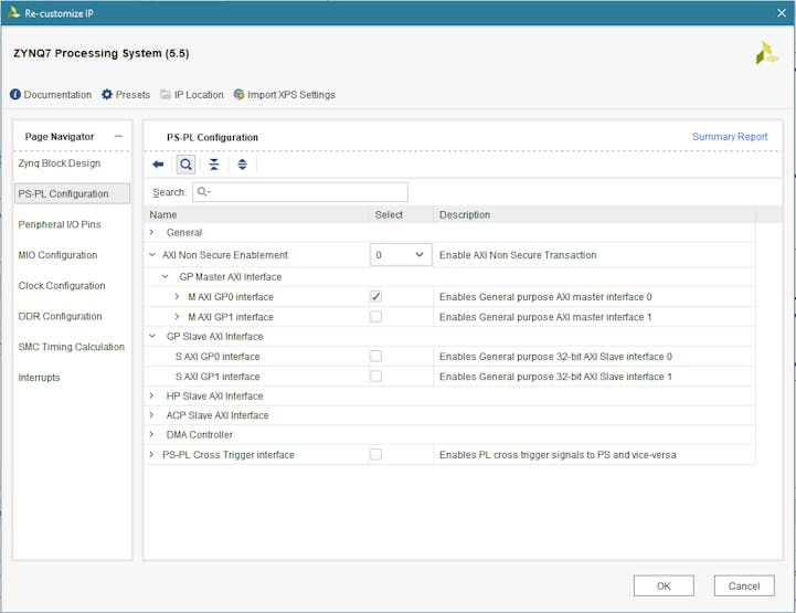
The next step is building the programmable hardware system. To do this add an AXI UART lite IP core which will be used to interface with the WIZ750SR via the serial protocol. Double click the AXI uart core and configure it to run at 115200 8N1.
The next component that will interface with the RGB LED is a custom RGB PWM (Pulse width modulator ) core. The complete design is shown below.

The beauty with FPGA is that you can instantiate any hardware interface to any pin that you like because it’s programmable logic.
Custom PWM AXI Core
The custom PWM AXI core has three outputs which interface to the red, green and blue LEDs. This RGB PWM core allows one to change the duty cycle of each RGB LED independently. The code of the PWM core is shown below. This code is integrated on the AXI bus Verilog file RGB_PWM_v1_0_S00_AXI.v
   //comparator statements that drive the PWM signal
   assign PWM0 = slv_reg0 < counter ? 1'b0 : 1'b1;
   assign PWM1 = slv_reg1 < counter ? 1'b0 : 1'b1;
   assign PWM2 = slv_reg2 < counter ? 1'b0 : 1'b1;
   assign PWM3 = slv_reg3 < counter ? 1'b0 : 1'b1;
After instantiating the UART-Lite AXI peripheral core and the custom PWM RGB core the next step is to write the drivers for the ZYNQ ARM MPU. The drivers for the UART core is setup in polling mode. This allows one to continuously monitor the Wiz750SR to get the data from the Ethernet link and control the three RGB LEDs based on the received values.
The MiniZed has an Arduino-compatible footprint shield so pins 0, 1 are assigned to the UART core, with TXD1, RXD1, respectively. Pins A0, A1 and A2 of the Arduino MiniZed shield are connected to the RGB LED pins. To set these pins on the Zynq module one has to implement the constraints file which shows the complete pinout.
After the hardware was designed, the bitstream was exported as an HDF file. The SDK uses this bitstream to run the firmware.
Zynq Firmware
The firmware was coded using the Xilinx SDK. After creating a BSP and importing the HDF file, a state machine was implemented which receives serial data from the AXI UART1 core and based on the 3 decoded values sets the PWM duty cycle of each LED independently. The demo below shows the RGB console in action.
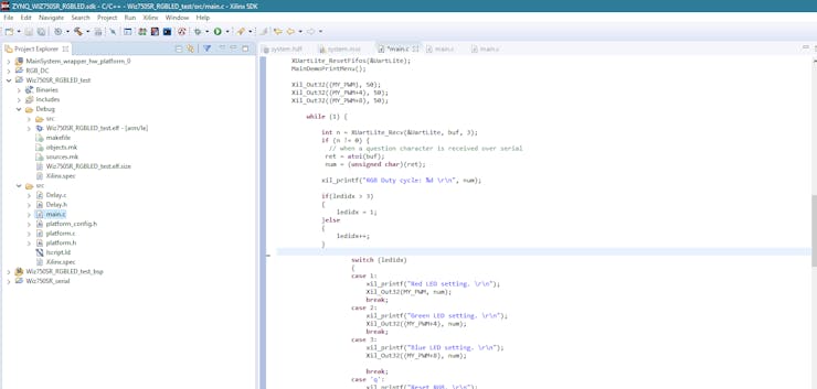
The same method can be used to control any transducers such as motors, LEDs, servos etc. The latency of the control depends on the serial speed which for this test case was set to 11500 baud.
Demo
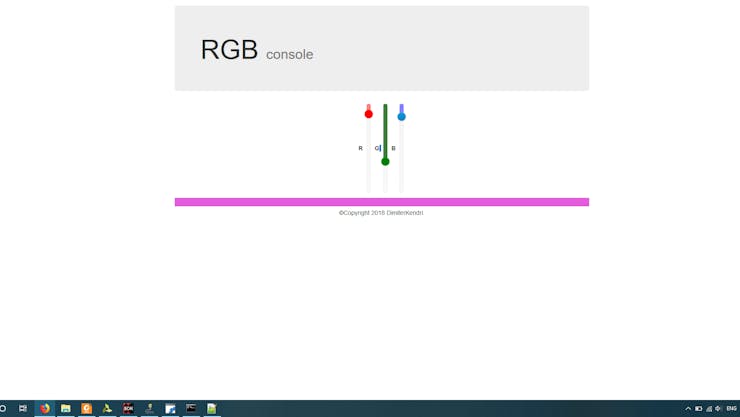
The complete system is shown below:
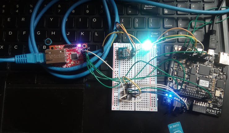
This concludes the demo. Code, including Python Flask web app, Zynq HW and Firmware is on the GitHub repo.
Future modifications may replace the RGB LED with a DC motor to allow control of a telescope via you browser.


