


W5500 and ESP-NOW Moto Gymkhana Timer: One Trigger, Two Paths
MGTS sends each photoelectric START and STOP event over ESP-NOW and W5500 UDP, then applies shared duplicate guards in an ESP32-C6 timing core.

WIZnet - W5500
x 3

One module on the main display and one on each of the two sensor nodes in the core BOM
📌 Overview
A START command is only five letters, but a timing system has to treat it with unusual care. If the command never arrives, the run has no valid beginning. If two copies are counted as two events, the timing state can be corrupted. Adding a second network path therefore solves only half of the problem. The receiver also needs to recognize that two packets may represent one physical trigger.
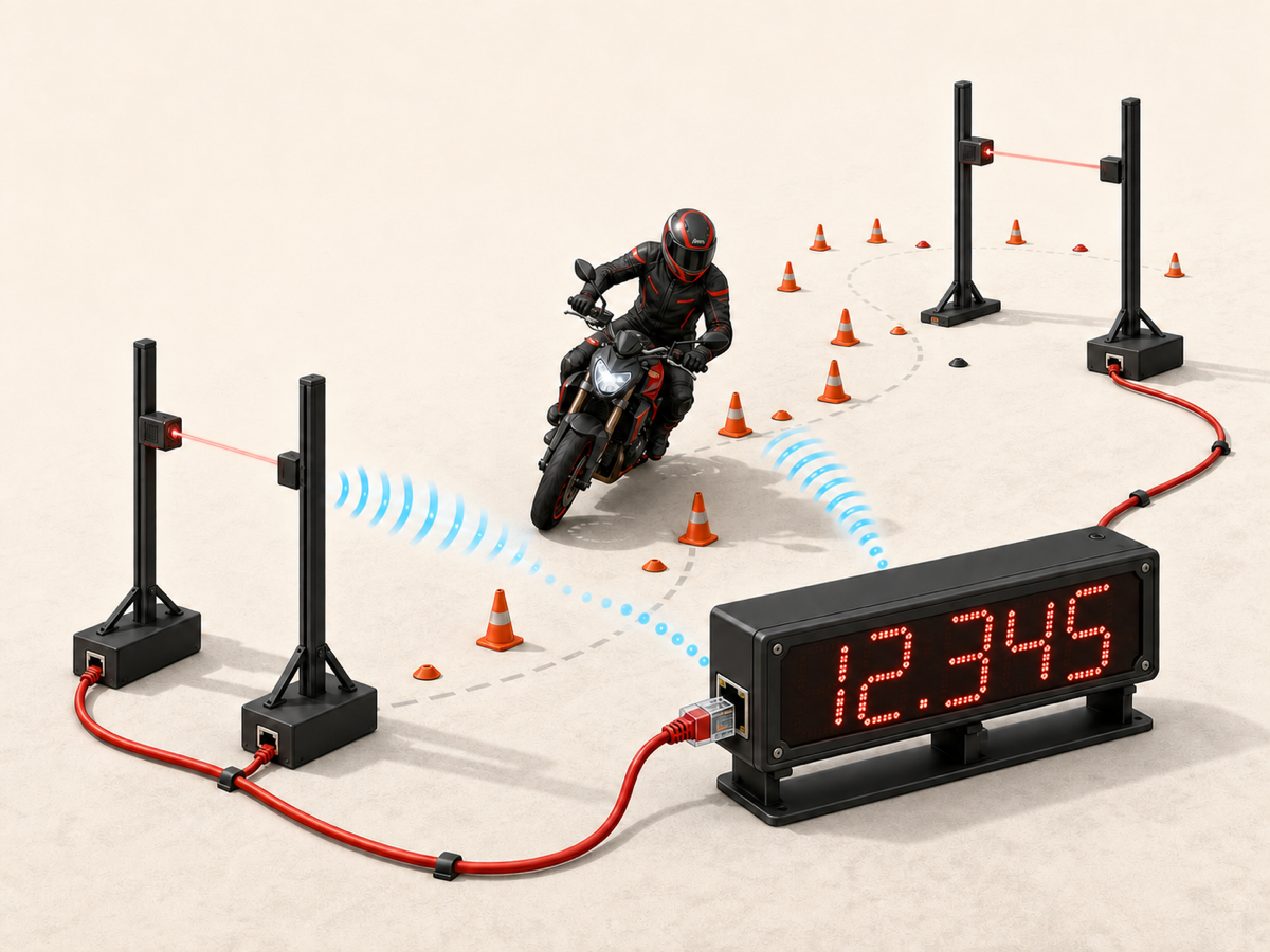
MGTS, the Moto Gymkhana Timing System, is GitHub developer uspat1234-bit's evolving answer to that problem. Its current development branch combines XIAO ESP32-C6 boards, Omron photoelectric sensors, a matrix LED display, ESP-NOW, and W5500 Ethernet. Each START or STOP node sends the same qualified beam event over radio and wired UDP. The main board accepts the event through a shared command handler and applies guards before changing the timer state.
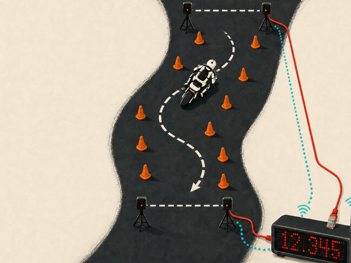
Moto Gymkhana is a timed motorcycle sport built around a cone course. Timing rules vary by organizer, but the start line and complete stop at the goal are decisive operational moments. MGTS focuses on the electronic chain around them: beam interruption, event delivery, duplicate handling, elapsed-time state, visible result, and operator workflow.
MGTS in one line: qualify one photoelectric trigger, send it by ESP-NOW and W5500 UDP, and apply one state-and-time guard before changing the timer.
Why One Timing Packet Matters
Ordinary telemetry can often send another temperature or status sample a moment later. A course-timing edge is different. The rider crosses it once, and the system has to preserve that event while ignoring rain, leaves, electrical noise, a blocked beam, and duplicate network copies.
A historical JAGE timing note makes the operational problem concrete. In an older one-photogate setup, start and finish signals could overlap, so an operator had to block the beam manually. MGTS supports a single-sensor practice mode, but its core hardware plan uses separate START and STOP nodes. That separation gives each physical line a clear role before networking begins.
The repository's strongest idea is not a performance number. It is a source-visible control pattern: filter at the edge, deliver over two media, and collapse close duplicates at one state machine. This pattern can be studied without assuming a specific packet-loss rate or timing accuracy.
One Trigger, Two Transport Paths
The START and STOP nodes follow the same pipeline. An Omron E3Z-R66 retro-reflective NPN sensor feeds the sensor board through a PC817 optocoupler, isolating its 12 V side from the ESP32-C6's 3.3 V logic. The firmware reads the isolated signal as an active-low input on GPIO21.
When the beam is interrupted, the input must remain LOW for at least 20 ms. After that qualification interval, the node creates either START or STOP. During the same trigger-handling pass, it makes two sequential ESP-NOW unicast calls, one to the main-board peer and one to the signal-board peer, then sends the same token as a W5500 UDP broadcast to 255.255.255.255:5005.
A one-shot lock prevents a continuously blocked beam from producing a packet stream. A sensor-side three-second guard limits fast retriggering. ESP-NOW is fixed to channel 1 in the relevant firmware, while the Ethernet path uses static addresses on one private subnet.
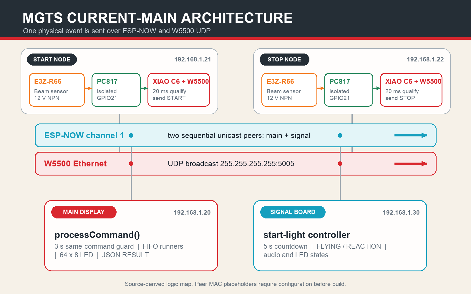
These paths are parallel, not a bridge and not automatic failover. The sensor does not wait for one path to fail before using the other. It attempts both, and the receivers decide what each arrival means.
⚙️ What the W5500 Actually Does
The WIZnet W5500 is a hardwired TCP/IP controller with an integrated 10/100 Ethernet MAC and PHY. MGTS connects a generic W5500 module to each XIAO ESP32-C6 over SPI and uses Arduino Ethernet.h UDP sockets. The project does not need an internet connection for timing. Its wired messages stay on a local Ethernet segment.
The exact sensor-node SPI map is useful for builders: CS is GPIO1, reset is GPIO2, SCK is GPIO19, MISO is GPIO20, and MOSI is GPIO18. The checked source assigns 192.168.1.20 to the main display, .21 to START, .22 to STOP, and .30 to the signal board. Every wired node listens or sends on UDP port 5005.
W5500's precise role: it provides the SPI-connected wired path for sensor commands and result traffic. The ESP32-C6 firmware still owns event acceptance, elapsed time, modes, and display state.
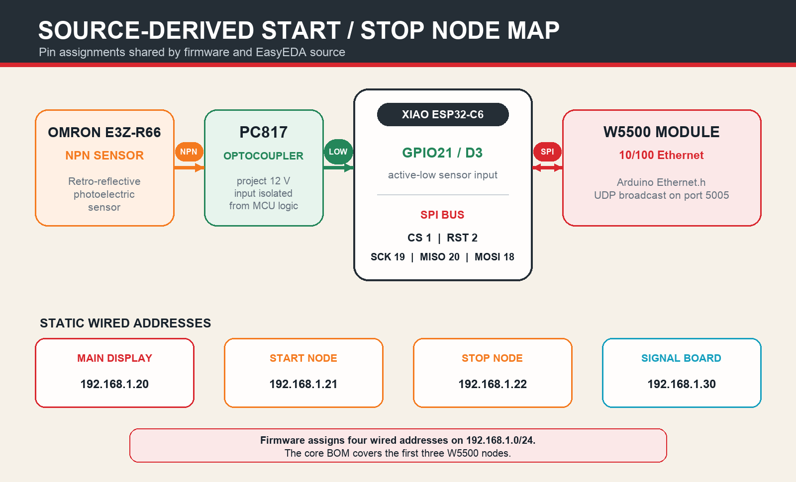
The BOM covers three W5500 modules for the main display and two sensor nodes. Later source also defines the signal board as a wired .30 node, so a complete current setup needs a common Ethernet segment, normally including a switch and cabling that are not listed in the original core BOM.
How the Main Board Turns Two Copies into One Event
The main board receives ESP-NOW data in its wireless callback and checks W5500 UDP in the main loop. Both routes feed the same processCommand() logic. That shared handler is the center of the design.
When the first valid START arrives, the board records the action and adds a runner. The code is intended to ignore another START inside the next three seconds, even if it arrived by the other network. STOP uses a corresponding guard. In normal multi-runner operation, STOP completes the oldest active runner, creating a FIFO timing queue of up to nine entries.
The duplicate logic is command-and-time based rather than packet-ID based. Packets contain no sensor timestamp or sequence number. The elapsed clock begins when the main board accepts the event, not when the photoelectric node first observed the beam. This makes the implementation easy to follow, while route-to-route timing calibration remains a separate engineering task.
After a STOP produces a result, the firmware holds it for one second, then broadcasts a compact JSON object over UDP and sends it to an ESP-NOW hub peer. The delay affects result reporting, not the already recorded elapsed value.
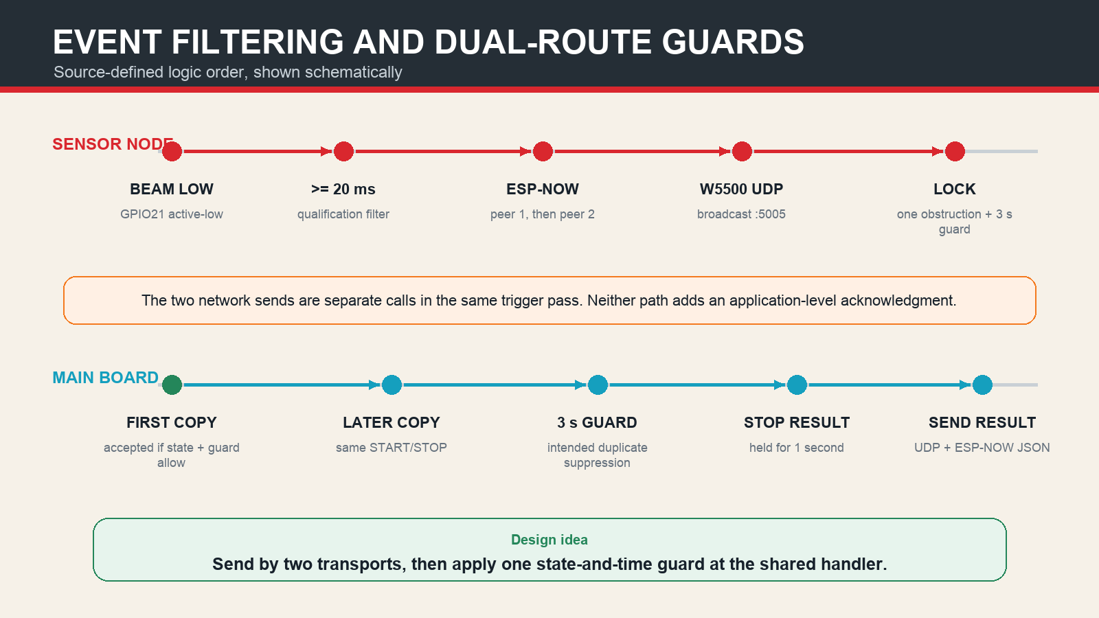
Layered event control: the 20 ms filter handles short input changes, the one-shot state handles a blocked beam, and the central three-second guard is intended to suppress close START or STOP copies from either transport.
There is no application-level acknowledgment, retransmission, or route reconciliation in the checked code. The ESP-NOW callback and Ethernet loop also share timing state without a queue or critical section, so simultaneous-arrival behavior belongs in a builder's target-hardware test plan. MGTS is best read as a clear dual-path event-delivery reference, with sequence IDs, acknowledgments, security, calibration, and field measurements available as future extensions.
Timing Modes, Signal Lights, and Operator Workflow
The extended main firmware provides three modes. MULT starts a new runner on START and completes the oldest runner on STOP. SOLO uses one START input as both edges: the first accepted event begins a run and the next completes it. SYNC receives SEQ_START and schedules its local timing origin five seconds later.
The signal-board firmware turns that sequence into an operator-visible countdown: first red at two seconds, second red at three, yellow at four, and green at five. A START before green produces a FLYING message; one after green produces REACTION. Signal and main boards each schedule from their own local millis() after receiving the command, so this is coordinated behavior rather than a shared-clock synchronization protocol.
A short main-board button press can force the active runner to the project's 999.999 DNF sentinel, while a long press cycles modes. The value is an MGTS workflow convention, not a universal Moto Gymkhana DNF code.
The repository's Python/Flet applications add the operator layer. They can import a rider CSV, read an NFC entry, send ENTRY by hub serial and UDP, receive RESULT through either route, maintain active runners, and export results. The voice variant adds spoken output, rankings, ratios, and manual result editing. Timing remains on the embedded main board; the desktop software supplies identities, presentation, and event operations.
What Builders Get, and What They Must Configure
This is a substantial public hardware-and-software repository. It includes firmware for START, STOP, main display, signal board, control hubs, and NFC; a BOM; four EasyEDA schematic/PCB JSON files; four segmented LED-enclosure STL files; and the Flet applications. The design reaches well beyond a single networking sketch.
The current branch is also an active prototype rather than a one-command build. A practical bring-up needs several deliberate steps:
- Put
sensor_start.inoandsensor_stop.inoin separate Arduino sketch folders, because both currently define their own globals,setup(), andloop()in one directory. - Choose either
main_board.inoormain_board_full.inoand isolate it for the same reason. - Replace placeholder peer bytes such as
0xXXand0xYY, then reconcile the concrete hub MAC addresses used by the later nodes. - Lock compatible ESP32 Arduino, ArduinoJson, Ethernet, LED, audio, NFC, and Flet dependencies, because the repository has no build manifest with versions.
- Bring up ESP-NOW and W5500 separately, then enable both and verify that one physical beam interruption creates one state transition.
- Define the tag format before combining the included NDEF tag writer with the embedded reader, which currently reads fixed raw bytes.
The repository does not declare a LICENSE. Review reuse and redistribution permission with the author before publishing a derivative design.
The Latest Release Is a Different Generation
MGTS changed architecture after its latest packaged release. The December 2025 v1.0 ZIP describes an earlier Wi-Fi 6 laptop-hotspot system with Windows applications, NFC, UDP, and Google Drive utilities. On June 15, 2026, the README and hardware direction were rewritten around ESP-NOW plus W5500. Signal, hub, NFC, app, and hardware work continued into July.
There is no tagged release for that later W5500 generation. Current main is 79 commits ahead of v1.0, and the release workflow still refers to files from the previous layout. The separate Android/Flet companion repository also follows the older hotspot and heartbeat protocol, so it should be read as an earlier companion track rather than the packaged interface for the current dual-path firmware.
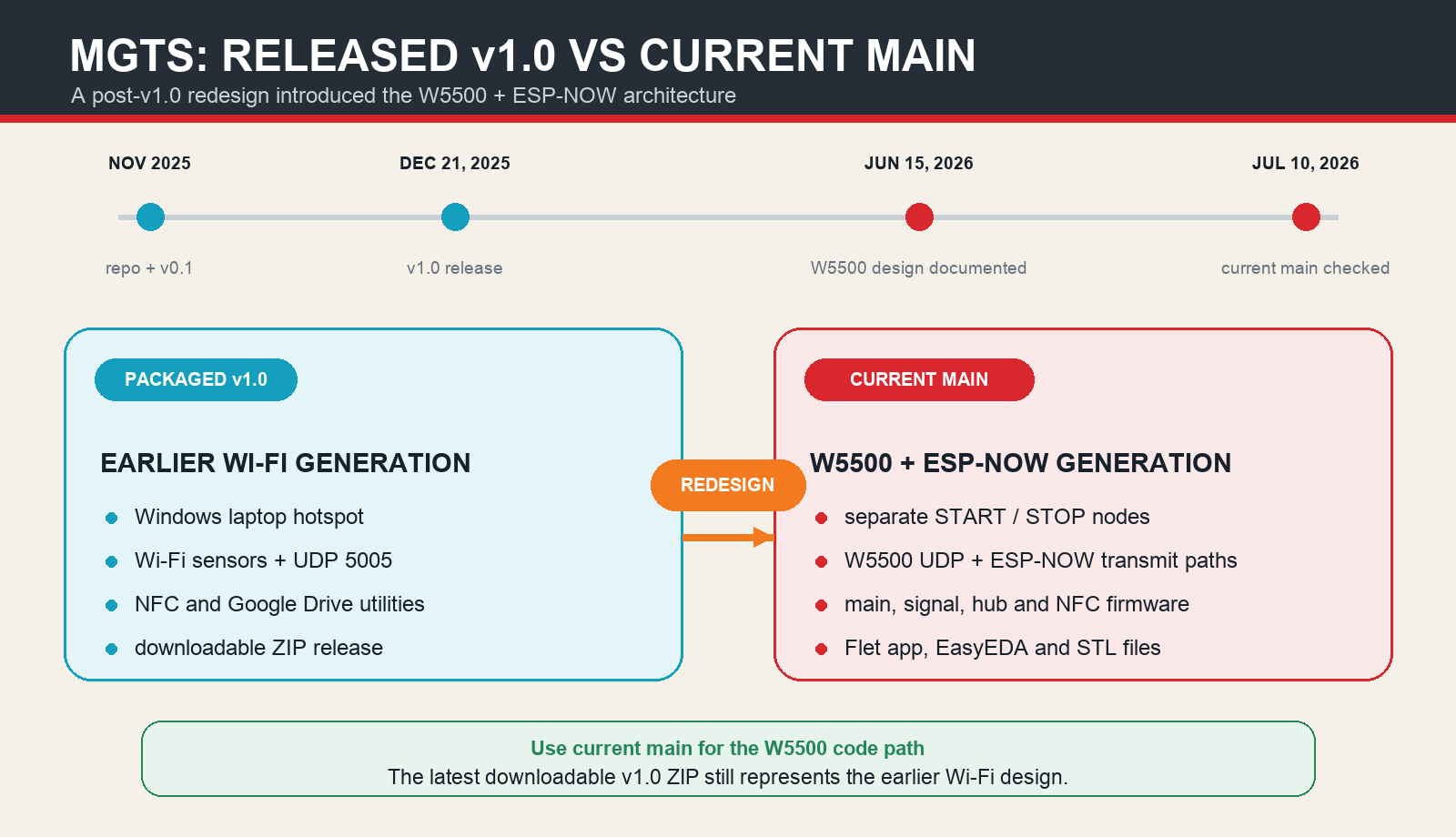
Version checkpoint: use the current main branch to study the W5500 and ESP-NOW implementation described here. Use v1.0 to inspect the earlier packaged Wi-Fi system.
Related WIZnet Maker Reading Path
ESP-NOW Differential Probe offers a useful topology comparison. Its remote ESP-NOW measurements are aggregated at an ESP32/W5500 gateway, while MGTS originates the same event at each gate and sends it over both media.
ArtNet to ESP-NOW DMX512 uses the same broad ESP32, W5500, ESP-NOW, and UDP ingredients in the opposite direction: Ethernet traffic enters a bridge and fans out over ESP-NOW.
For the motorsport data angle, PER, Purdue Electric Racing uses W5500 UDP broadcast for continuous Formula SAE telemetry. MGTS instead moves small, discrete photoelectric events that change a course-timing state.
Source-Backed Summary
MGTS connects a physical race-course edge to an embedded result in a traceable sequence: E3Z-R66 beam break, PC817 isolation, 20 ms qualification, ESP-NOW unicasts plus W5500 UDP broadcast, shared command guard, ESP32-C6 timing state, LED result, and Flet operator workflow.
Its most reusable lesson is larger than any one protocol. A second transport becomes useful only when the application defines what counts as the same event. MGTS makes that decision visible in code, hardware files, timing modes, and the lifecycle of an ambitious maker system.
❓ FAQ
Q. What does MGTS use the W5500 for? Each wired node uses the W5500 as its local Ethernet interface. START and STOP sensors broadcast their event on UDP port 5005, and the main board also publishes result JSON over UDP.
Q. Are ESP-NOW and W5500 configured as automatic failover? No. A qualified sensor event attempts both routes during the same trigger pass. Close matching arrivals converge on the same handler, where the three-second action guard is intended to suppress a second transition.
Q. Where is elapsed time captured? In this implementation, the main board records millis() when it accepts START or STOP. Sensor packets do not carry a source timestamp or sequence number.
Q. Can the current repository compile exactly as cloned? It needs preparation. Separate the competing Arduino sketch variants, replace placeholder MAC bytes, reconcile peer constants, and install compatible libraries before building each target.
Q. Which download contains the W5500 architecture? The current main branch contains the W5500 plus ESP-NOW source. The latest tagged v1.0 release contains the earlier Wi-Fi-hotspot generation.
한국어 (Korean)
📌 개요
START는 다섯 글자뿐인 명령이지만, 계측 시스템은 이를 아주 신중하게 다뤄야 합니다. 명령이 도착하지 않으면 출발 시점이 사라지고, 두 개의 복사본을 두 번의 이벤트로 처리하면 계측 상태가 틀어질 수 있습니다. 따라서 두 번째 네트워크 경로를 추가하는 것만으로는 문제의 절반만 해결됩니다. 수신기도 두 패킷이 하나의 물리적 트리거를 뜻할 수 있다는 사실을 알아야 합니다.
MGTS, Moto Gymkhana Timing System은 GitHub 개발자 uspat1234-bit가 이 문제를 풀기 위해 발전시키고 있는 프로젝트입니다. 현재 개발 브랜치는 XIAO ESP32-C6, Omron 광전 센서, 매트릭스 LED 디스플레이, ESP-NOW, W5500 Ethernet을 결합합니다. START와 STOP 노드는 조건을 통과한 동일한 빔 이벤트를 무선과 유선 UDP로 보냅니다. 메인 보드는 공통 명령 핸들러로 이벤트를 받아 가드를 적용한 뒤 타이머 상태를 바꿉니다.
모토짐카나는 콘으로 만든 코스를 달리는 시간을 겨루는 모터사이클 종목입니다. 세부 규칙은 주최 단체마다 다르지만 출발선을 통과하는 순간과 골 지점에서 완전히 정지하는 절차는 운영상 매우 중요합니다. MGTS는 그 순간을 둘러싼 전자적 흐름에 집중합니다. 빔 차단, 이벤트 전송, 중복 처리, 경과 시간 상태, 결과 표시, 운영자 워크플로가 하나로 이어집니다.
한 문장으로 보는 MGTS: 하나의 광전 트리거를 확인하고, ESP-NOW와 W5500 UDP로 보낸 뒤, 타이머를 바꾸기 전에 하나의 상태·시간 가드를 적용합니다.
하나의 계측 패킷이 중요한 이유
일반 텔레메트리는 잠시 후 온도나 상태 샘플을 다시 보낼 수 있습니다. 코스 계측의 에지는 다릅니다. 라이더는 그 지점을 한 번 통과하고, 시스템은 비, 낙엽, 전기적 노이즈, 계속 가려진 빔, 네트워크 중복 패킷을 무시하면서 그 이벤트를 보존해야 합니다.
JAGE의 과거 계측 기록은 운영 문제를 구체적으로 보여 줍니다. 예전의 단일 광전 게이트 구성에서는 출발과 골 신호가 겹칠 수 있어 운영자가 직접 빔을 막아야 했습니다. MGTS도 연습용 단일 센서 모드를 지원하지만, 핵심 하드웨어 계획은 START와 STOP 노드를 분리합니다. 네트워크로 보내기 전부터 각 물리적 지점의 역할을 분명하게 만드는 구성입니다.
이 저장소에서 가장 흥미로운 것은 성능 수치가 아니라 코드로 확인할 수 있는 제어 패턴입니다. 에지에서 입력을 걸러내고, 두 매체로 전달하며, 하나의 상태 머신에서 가까운 중복을 합칩니다. 특정 패킷 손실률이나 계측 정확도를 가정하지 않고도 이 패턴을 살펴볼 수 있습니다.
하나의 트리거, 두 개의 전송 경로
START와 STOP 노드는 같은 파이프라인을 사용합니다. Omron E3Z-R66 반사형 NPN 센서가 PC817 옵토커플러를 통해 센서 보드로 들어옵니다. 12 V 센서 측과 ESP32-C6의 3.3 V 로직 측을 절연하고, 펌웨어는 GPIO21에서 active-low 신호를 읽습니다.
빔이 끊기면 입력은 최소 20 ms 동안 LOW를 유지해야 합니다. 이 확인 구간을 통과하면 노드는 START 또는 STOP을 만듭니다. 같은 트리거 처리 루프 안에서 메인 보드와 신호 보드에 ESP-NOW 유니캐스트를 순서대로 두 번 호출하고, 이어서 동일한 토큰을 W5500 UDP 브로드캐스트 255.255.255.255:5005로 보냅니다.
원샷 잠금은 빔이 계속 가려진 상태에서 패킷이 반복되는 것을 막습니다. 센서 측의 3초 가드는 너무 빠른 재트리거를 제한합니다. 관련 펌웨어의 ESP-NOW 채널은 1로 고정돼 있고, Ethernet 경로는 하나의 사설 서브넷에서 고정 주소를 사용합니다.
두 경로는 브리지도 아니고 자동 전환식 백업도 아닙니다. 센서는 한 경로가 실패할 때까지 기다리지 않습니다. 두 경로 모두로 전송을 시도하고, 수신기가 각 도착의 의미를 결정합니다.
⚙️ W5500이 실제로 맡는 역할
WIZnet W5500은 10/100 Ethernet MAC과 PHY가 통합된 하드와이어드 TCP/IP 컨트롤러입니다. MGTS는 범용 W5500 모듈을 SPI로 각 XIAO ESP32-C6에 연결하고 Arduino Ethernet.h의 UDP 소켓을 사용합니다. 계측에 인터넷 연결은 필요하지 않으며, 유선 메시지는 로컬 Ethernet 세그먼트 안에서 이동합니다.
센서 노드의 정확한 SPI 매핑은 CS GPIO1, reset GPIO2, SCK GPIO19, MISO GPIO20, MOSI GPIO18입니다. 확인한 소스에서 메인 디스플레이는 192.168.1.20, START는 .21, STOP은 .22, 신호 보드는 .30을 사용합니다. 모든 유선 노드는 UDP 포트 5005로 송수신합니다.
W5500의 정확한 역할: 센서 명령과 결과 트래픽을 위한 SPI 연결 유선 경로를 제공합니다. 이벤트 수락, 경과 시간, 모드, 디스플레이 상태는 ESP32-C6 펌웨어가 결정합니다.
BOM에는 메인 디스플레이와 두 센서 노드에 사용할 W5500 모듈 3개가 포함됩니다. 이후 소스는 신호 보드도 유선 .30 노드로 정의합니다. 따라서 현재 구성을 완성하려면 공통 Ethernet 세그먼트가 필요하며, 보통 초기 핵심 BOM에 없는 스위치와 케이블도 준비해야 합니다.
메인 보드는 두 복사본을 어떻게 한 이벤트로 만드나?
메인 보드는 무선 콜백에서 ESP-NOW 데이터를 받고, 메인 루프에서 W5500 UDP를 확인합니다. 두 경로 모두 동일한 processCommand() 로직으로 들어갑니다. 이 공통 핸들러가 설계의 중심입니다.
첫 번째 유효한 START가 도착하면 보드는 동작 시각을 기록하고 러너를 추가합니다. 코드는 다른 네트워크 경로에서 왔더라도 이후 3초 안의 START를 무시하도록 작성돼 있습니다. STOP도 같은 방식의 가드를 사용합니다. 일반적인 다중 러너 동작에서는 STOP이 가장 오래된 활성 러너를 완료하므로 최대 9개 항목의 FIFO 계측 큐가 만들어집니다.
중복 로직은 패킷 ID가 아니라 명령 종류와 시간에 기반합니다. 패킷에는 센서 타임스탬프나 시퀀스 번호가 없습니다. 경과 시간은 광전 노드가 빔을 처음 본 시점이 아니라 메인 보드가 이벤트를 수락한 시점에서 시작됩니다. 구현 흐름은 이해하기 쉽고, 경로별 시간 보정은 별도의 엔지니어링 과제로 남습니다.
STOP이 결과를 만들면 펌웨어는 이를 1초 동안 보류한 뒤 UDP로 JSON을 브로드캐스트하고 ESP-NOW 허브 피어에도 보냅니다. 이 지연은 이미 기록된 경과 시간이 아니라 결과 보고 시점에 적용됩니다.
계층별 이벤트 제어: 20 ms 필터는 짧은 입력 변화를, 원샷 상태는 계속 가려진 빔을, 중앙의 3초 가드는 어느 전송 경로에서 오든 가까운 START 또는 STOP 복사본을 억제하도록 설계됐습니다.
확인한 코드에는 애플리케이션 수준의 ACK, 재전송, 경로 조정 로직이 없습니다. ESP-NOW 콜백과 Ethernet 루프는 큐나 임계 구역 없이 계측 상태를 공유하므로 동시 도착 동작도 실제 타깃 하드웨어에서 확인해야 합니다. 따라서 MGTS는 명확한 이중 경로 이벤트 전송 레퍼런스로 읽는 것이 좋습니다. 시퀀스 ID, ACK, 보안, 보정, 현장 측정은 이후 확장할 수 있습니다.
계측 모드, 신호등, 운영자 워크플로
확장형 메인 펌웨어는 세 가지 모드를 제공합니다. MULT는 START로 새 러너를 시작하고 STOP으로 가장 오래된 러너를 완료합니다. SOLO는 하나의 START 입력을 출발과 종료에 함께 사용해 첫 이벤트로 시작하고 다음 이벤트로 완료합니다. SYNC는 SEQ_START를 받은 뒤 5초 후의 로컬 시점을 시간 원점으로 예약합니다.
신호 보드 펌웨어는 이 명령을 운영자가 볼 수 있는 카운트다운으로 바꿉니다. 2초에 첫 번째 적색, 3초에 두 번째 적색, 4초에 황색, 5초에 녹색이 켜집니다. 녹색 전에 START가 들어오면 FLYING, 녹색 이후에는 REACTION을 만듭니다. 신호 보드와 메인 보드는 명령을 받은 뒤 각자의 millis()로 예약하므로 공유 시계 동기화 프로토콜이 아니라 조정된 동작입니다.
메인 보드 버튼을 짧게 누르면 활성 러너를 프로젝트의 999.999 DNF 센티널로 강제할 수 있고, 길게 누르면 모드를 순환합니다. 이 값은 MGTS 운영 규칙이며 모토짐카나 전체의 공통 DNF 코드가 아닙니다.
저장소의 Python/Flet 애플리케이션은 운영자 계층을 더합니다. 러너 CSV 가져오기, NFC 엔트리 읽기, 허브 시리얼과 UDP를 통한 ENTRY 전송, 두 경로의 RESULT 수신, 활성 러너 관리, 결과 내보내기를 처리할 수 있습니다. 음성 버전은 TTS, 순위, 비율, 수동 결과 편집을 추가합니다. 계측은 임베디드 메인 보드가 담당하고 데스크톱 소프트웨어는 신원, 표시, 경기 운영을 맡습니다.
제작자가 얻는 자료와 직접 설정할 부분
이 저장소에는 상당한 분량의 하드웨어와 소프트웨어 자료가 공개돼 있습니다. START, STOP, 메인 디스플레이, 신호 보드, 제어 허브, NFC 펌웨어와 BOM, EasyEDA 회로도/PCB JSON 4개, 분할형 LED 케이스 STL 4개, Flet 애플리케이션이 포함됩니다. 단일 네트워크 예제를 훨씬 넘어선 설계입니다.
동시에 현재 브랜치는 명령 한 번으로 빌드되는 완제품보다 활발히 발전 중인 프로토타입에 가깝습니다. 실제 bring-up에는 다음 정리가 필요합니다.
sensor_start.ino와sensor_stop.ino는 각각 전역 변수,setup(),loop()를 정의하므로 별도 Arduino 스케치 폴더로 나눕니다.- 같은 이유로
main_board.ino와main_board_full.ino중 하나를 선택해 분리합니다. 0xXX,0xYY같은 피어 주소 자리표시자를 바꾸고, 후기에 추가된 노드의 실제 허브 MAC 상수도 서로 맞춥니다.- 버전이 고정된 빌드 매니페스트가 없으므로 ESP32 Arduino, ArduinoJson, Ethernet, LED, audio, NFC, Flet 의존성을 호환되는 조합으로 고정합니다.
- ESP-NOW와 W5500을 각각 먼저 확인한 다음 둘을 함께 켜서 한 번의 물리적 빔 차단이 하나의 상태 전이만 만드는지 확인합니다.
- 포함된 NDEF 태그 writer와 고정 raw byte를 읽는 임베디드 reader를 결합하기 전에 태그 형식을 정의합니다.
저장소에는 LICENSE가 선언돼 있지 않습니다. 파생 설계를 공개하거나 재배포하기 전에 제작자와 재사용 권한을 확인해야 합니다.
최신 릴리스는 다른 세대의 시스템
MGTS는 최신 패키지 릴리스 이후 아키텍처를 바꿨습니다. 2025년 12월의 v1.0 ZIP은 Windows 애플리케이션, NFC, UDP, Google Drive 유틸리티가 포함된 이전 Wi-Fi 6 노트북 hotspot 시스템을 설명합니다. 2026년 6월 15일 README와 하드웨어 방향이 ESP-NOW와 W5500 조합으로 다시 작성됐고, 7월까지 신호, 허브, NFC, 앱, 하드웨어 작업이 이어졌습니다.
이후 W5500 세대에 해당하는 태그 릴리스는 없습니다. 현재 main은 v1.0보다 79개 커밋 앞서 있으며, 릴리스 워크플로는 여전히 이전 레이아웃의 파일을 참조합니다. 별도 Android/Flet companion 저장소도 과거 hotspot과 heartbeat 프로토콜을 사용하므로 현재 이중 경로 펌웨어의 패키지 인터페이스보다 이전 세대의 companion 개발 트랙으로 보는 것이 정확합니다.
버전 체크포인트: 여기서 설명한 W5500과 ESP-NOW 구현은 현재 main 브랜치에서 살펴봐야 합니다. v1.0은 이전 패키지형 Wi-Fi 시스템을 확인할 때 사용합니다.
관련 WIZnet Maker 읽을거리
ESP-NOW Differential Probe는 토폴로지를 비교하기 좋은 프로젝트입니다. 원격 ESP-NOW 계측값을 ESP32/W5500 gateway에서 모으는 구조인 반면, MGTS는 각 게이트에서 같은 이벤트를 만들어 두 매체로 전송합니다.
ArtNet to ESP-NOW DMX512는 ESP32, W5500, ESP-NOW, UDP라는 비슷한 구성 요소를 반대 방향으로 사용합니다. Ethernet 트래픽이 브리지로 들어오고 ESP-NOW로 fan-out됩니다.
모터스포츠 데이터 관점에서는 PER, Purdue Electric Racing이 W5500 UDP 브로드캐스트로 연속적인 Formula SAE 텔레메트리를 보냅니다. MGTS는 코스 계측 상태를 바꾸는 작고 불연속적인 광전 이벤트를 전송한다는 차이가 있습니다.
출처 기반 요약
MGTS는 물리적인 코스 에지를 임베디드 결과로 이어지는 순서로 연결합니다. E3Z-R66 빔 차단, PC817 절연, 20 ms 확인, ESP-NOW 유니캐스트와 W5500 UDP 브로드캐스트, 공통 명령 가드, ESP32-C6 계측 상태, LED 결과, Flet 운영 워크플로가 하나의 흐름을 만듭니다.
가장 재사용할 만한 교훈은 개별 프로토콜보다 큽니다. 두 번째 전송 경로는 애플리케이션이 무엇을 같은 이벤트로 볼지 정의할 때 비로소 유용해집니다. MGTS는 그 결정을 코드, 하드웨어 파일, 계측 모드, 프로젝트의 발전 과정 안에서 보여 줍니다.
❓ FAQ
Q. MGTS는 W5500을 어디에 사용하나요? 각 유선 노드의 로컬 Ethernet 인터페이스로 사용합니다. START와 STOP 센서는 UDP 포트 5005로 이벤트를 브로드캐스트하고, 메인 보드도 UDP로 결과 JSON을 보냅니다.
Q. ESP-NOW와 W5500은 자동 failover로 구성됐나요? 아닙니다. 조건을 통과한 센서 이벤트는 같은 트리거 처리에서 두 경로 모두로 전송을 시도합니다. 가까운 동일 명령은 하나의 핸들러로 들어가며 3초 동작 가드는 두 번째 전이를 억제하도록 작성돼 있습니다.
Q. 경과 시간은 어디에서 기록하나요? 이 구현에서는 메인 보드가 START 또는 STOP을 수락할 때 millis()를 기록합니다. 센서 패킷에는 원본 타임스탬프나 시퀀스 번호가 없습니다.
Q. 현재 저장소를 clone한 그대로 컴파일할 수 있나요? 준비 작업이 필요합니다. 서로 충돌하는 Arduino 스케치 변형을 분리하고, MAC 자리표시자를 바꾸며, 피어 상수를 맞추고, 호환 라이브러리를 설치해야 합니다.
Q. W5500 아키텍처는 어떤 다운로드에 들어 있나요? W5500과 ESP-NOW 소스는 현재 main 브랜치에 있습니다. 최신 태그 v1.0 릴리스에는 이전 Wi-Fi hotspot 세대가 들어 있습니다.
-
Moto Gymkhana Timing System source
Current hardware, firmware, enclosure, BOM, and desktop-app sources

-
Main display firmware
Pinned main timing, mode, ESP-NOW, W5500 UDP, and result path
-
START sensor firmware
Pinned photoelectric input, guards, ESP-NOW peer sends, and UDP broadcast
-
Signal board firmware
Pinned countdown, FLYING/REACTION, ESP-NOW, and W5500 UDP source
-
MGTS v1.0 release
Earlier packaged Wi-Fi generation, preceding the current W5500 redesign
-
WIZnet W5500 documentation
Official W5500 product documentation
-
ESP-NOW API reference
Official ESP32-C6 ESP-NOW API reference


