
How do you control Ethernet, LCD, and LED Matrix all at once with a $1 STM32 Blue Pill?
STM32F103C8T6 (Blue Pill) + W5500 Multi-Display IoT Starter

WIZnet - W5500
x 1
STMicroelectronics - STM32F103RCT6
x 1
STM32F103C8T6 (Blue Pill) + W5500 Multi-Display IoT Starter
A Vietnamese embedded developer built this open-source starter project that combines WIZnet's W5500 Ethernet module with STM32F103C8T6, routing received TCP data simultaneously to an LCD 1602 and a P10 LED Matrix — all in pure C with no OS. Started just 2 weeks ago and actively growing.
| Component | Specification | Role |
|---|---|---|
| STM32F103C8T6 (Blue Pill) | ARM Cortex-M3, 72MHz, 64KB Flash, 20KB RAM | Main MCU |
| W5500 | Hardwired TCP/IP, SPI interface, up to 80MHz | Ethernet communication |
| LCD 1602 I2C | 16x2 characters, PCF8574 I2C adapter (0x27 / 0x3F) | Display received data |
| P10 LED Matrix | 32×16 pixels, HUB12 interface, 1/4 scan | Scrolling text output |
| ST-Link V2 | SWD debugger / programmer | Firmware upload |
1. What This Project Does
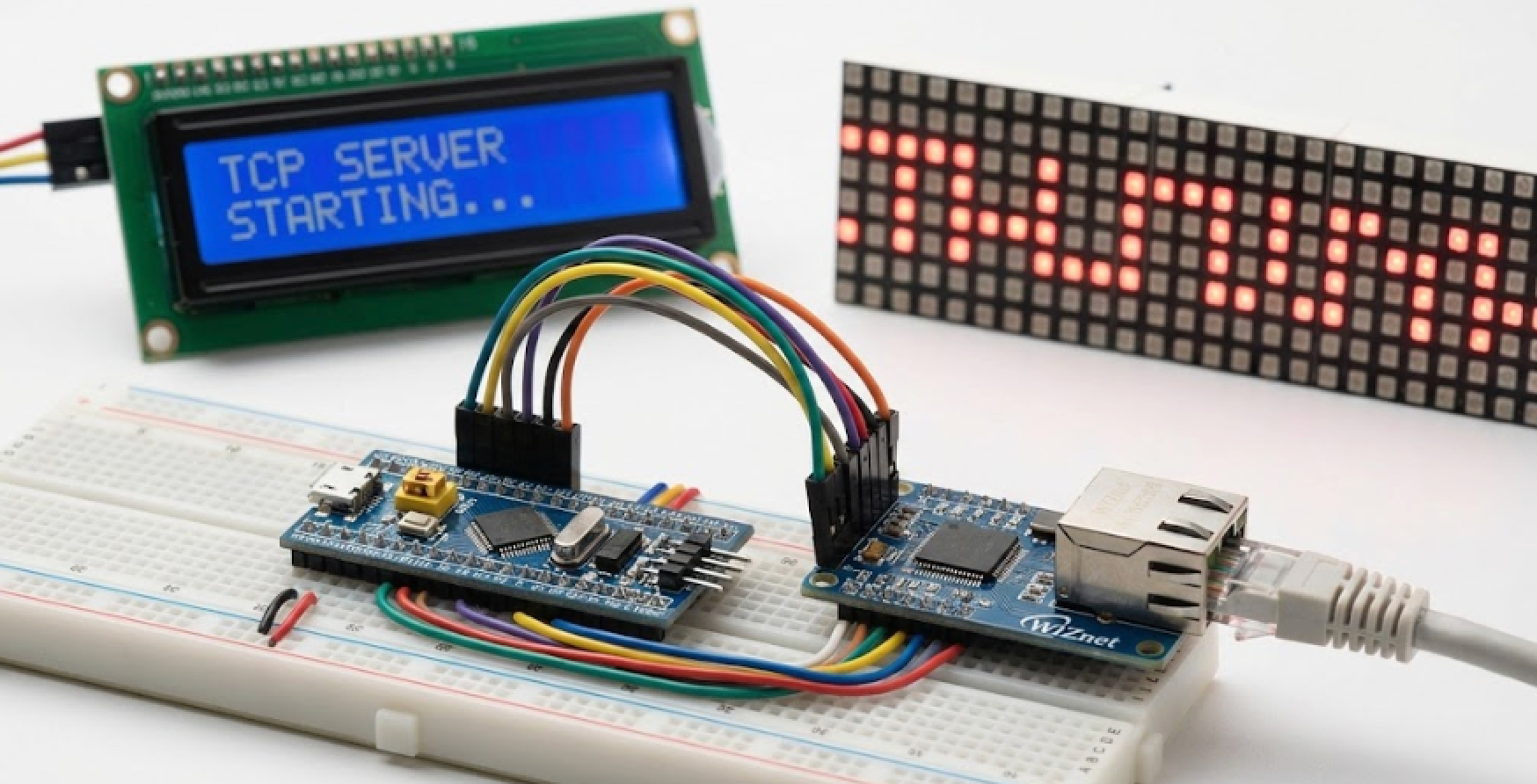
This project implements a TCP Echo Server on an STM32F103C8T6 ("Blue Pill") using the WIZnet W5500 Ethernet module, then pipes received data to two displays simultaneously — an LCD 1602 over I2C and a P10 LED Matrix over HUB12.
"Project STM32F103C8T6 với thư viện W5500 Ethernet." — Author's README opening line
The data flow is straightforward:
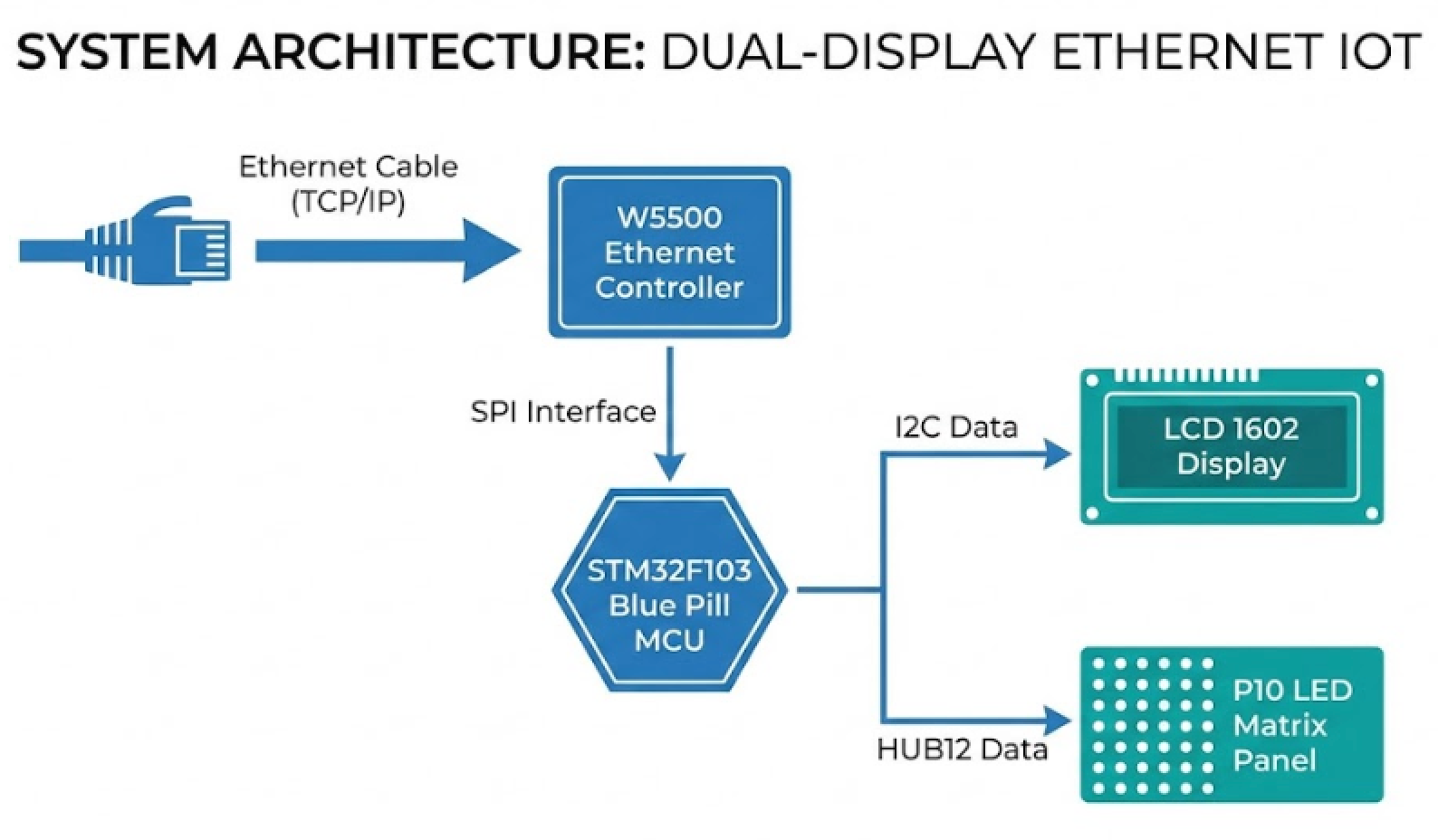
No RTOS, no middleware — just bare-metal C, CMake, and WIZnet's official socket library. It's a clean, readable reference for anyone learning embedded networking on a budget board.
2. Who Built This — and Why It's Worth Watching
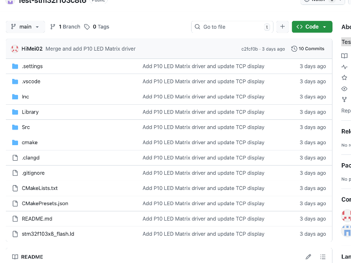
This project comes from a Vietnamese embedded developer (ili-vbot-ili, 2 contributors) who started from scratch on February 5, 2026 and has been shipping new features every few days since. The README is written in Vietnamese, which tells you this is a hands-on learning build — not a polished product release — but the hardware design, pin wiring diagrams, and code structure are clean and universally readable.
The update history speaks for itself:
| Date | What Was Added |
|---|---|
| 2026-02-05 | Project created, W5500 library integrated, TCP Echo Server |
| 2026-02-05 | LCD 1602 I2C driver added, W5500 received data → LCD output |
| 2026-02-05 | IntelliSense config, successful build confirmed |
| 2026-02-06 | P10 LED Matrix driver (HUB12, TIM3 auto-refresh, built-in 5×7 font) |
| 2026-02-10 | flash.ps1 script — one-click firmware upload via ST-Link or UART |
Two weeks in, and it already covers Ethernet, dual-display output, and automated flashing. Still actively updated.
3. Why W5500 Makes Sense Here
The Blue Pill only has 20KB of RAM. Running a software TCP/IP stack on it would eat half that budget before you write a single line of application logic. W5500 solves this by handling the entire TCP/IP stack in hardware, offloading it completely from the MCU.
| Factor | Detail |
|---|---|
| Voltage compatibility | W5500 runs at 3.3V — direct connection to STM32, no level shifter needed |
| SPI speed | W5500 supports up to 80MHz; Blue Pill SPI1 tops at 36MHz — fully compatible |
| GPIO conflict avoidance | W5500 on GPIOA (PA4–PA7), P10 on GPIOB (PB10–PB15) — zero pin conflicts |
| Independent TCP/IP stack | W5500's internal 32KB buffer handles networking; MCU RAM stays free for your logic |
The project integrates WIZnet's official ioLibrary (wizchip_conf, socket.c/.h) directly — no custom TCP reimplementation, no guesswork.
4. Confirmed Build Footprint
From the author's own history log after the initial successful build:
FLASH:  10,008 B  →  15.27% of 64KB used
RAM:    4,136 B   →  20.20% of 20KB used
Ethernet + dual-display control running in under one-fifth of total resources. Plenty of headroom left for user application logic.
5. Pin Layout at a Glance
STM32F103C8T6 (Blue Pill)
│
├── GPIOA (SPI1) ──────────── W5500 Ethernet
│   ├── PA4  → CS
│   ├── PA5  → SCK
│   ├── PA6  → MISO
│   ├── PA7  → MOSI
│   ├── PB0  → RST  (optional)
│   └── PB1  → INT  (optional)
│
├── GPIOB (I2C1) ──────────── LCD 1602 I2C (PCF8574)
│   ├── PB6  → SCL
│   └── PB7  → SDA
│
├── GPIOB ─────────────────── P10 LED Matrix (HUB12)
│   ├── PB10 → OE
│   ├── PB11 → A
│   ├── PB12 → B
│   ├── PB13 → CLK
│   ├── PB14 → LAT/STB
│   └── PB15 → DATA/R
│
└── PA13 / PA14 ────────────── ST-Link (SWD)
Keeping W5500 on GPIOA and P10 on GPIOB is the key design decision that lets SPI, I2C, and HUB12 all run simultaneously without any pin conflicts.
6. Build Environment
Pure CMake + Ninja — no IDE lock-in.
| Tool | Role |
|---|---|
| VS Code + STM32 Extension | Primary development environment |
| GNU Arm Embedded Toolchain | Compiler |
| CMake ≥ 3.20 + Ninja | Build system |
| STM32CubeProgrammer CLI | Firmware flashing |
| flash.ps1 (PowerShell) | One-click flash script (ST-Link or UART) |
Build output includes .elf, .hex, .bin, and .map. Flash via ST-Link SWD (recommended) or USB-TTL UART bootloader.
FAQ
Q1: Does connecting W5500 to STM32F103C8T6 require a level shifter? No. W5500 operates at 3.3V IO and so does the STM32F103C8T6, so you can wire them directly. Only the LCD 1602 and P10 LED Matrix need a 5V VCC supply line.
Q2: What SPI speed should I configure for W5500 on this board? W5500 supports up to 80MHz, but the Blue Pill's SPI1 maxes out at 36MHz. The author recommends staying at or below 33MHz. Set this via your SPI prescaler in the MCU initialization code.
Q3: My LCD isn't showing anything. What should I check first? The most common cause is an I2C address mismatch. PCF8574-based adapters typically use 0x27, while PCF8574A uses 0x3F. Change LCD_I2C_ADDR in Library/lcd1602/lcd_i2c.h to match your module. You can also run a quick I2C scanner firmware to confirm the address.
Q4: How does P10 LED Matrix auto-refresh work without blocking the main loop? The project uses TIM3 configured with a 1ms interrupt that calls P10_Refresh() automatically. You only need to call P10_SetupTimer() once during initialization — after that, the display stays alive independently while your main loop handles Ethernet and logic.
Q5: Do I need to connect the W5500 INT pin? No, it's marked optional in the README. The project works in polling mode without it. If you want interrupt-driven packet reception, connect INT to PB1 and add the handler yourself.
Q6: Can I build this without STM32CubeIDE installed? Yes. The project is fully CMake-based. Run cmake --preset Debug to configure, then cmake --build build/Debug to compile. STM32CubeIDE is not required — only the GNU Arm Embedded Toolchain and CMake ≥ 3.20 are needed.
Q7: The README is in Vietnamese — can developers from other regions use this without issues? Absolutely. The pin wiring tables, ASCII connection diagrams, function reference tables, and build commands are all in a universal format. The WIZnet ioLibrary itself is documented in English. The Vietnamese text covers setup notes and explanations, but nothing in the code or hardware design is language-dependent.