
Powering 57,000 LEDs: A Custom Motherboard for W5500-EVB-Pico
Open-source KiCad PCB acting as a power distribution and SPI hub motherboard for W5100S/W5500-EVB-Pico, driving six LED lamp units in a university building-scal

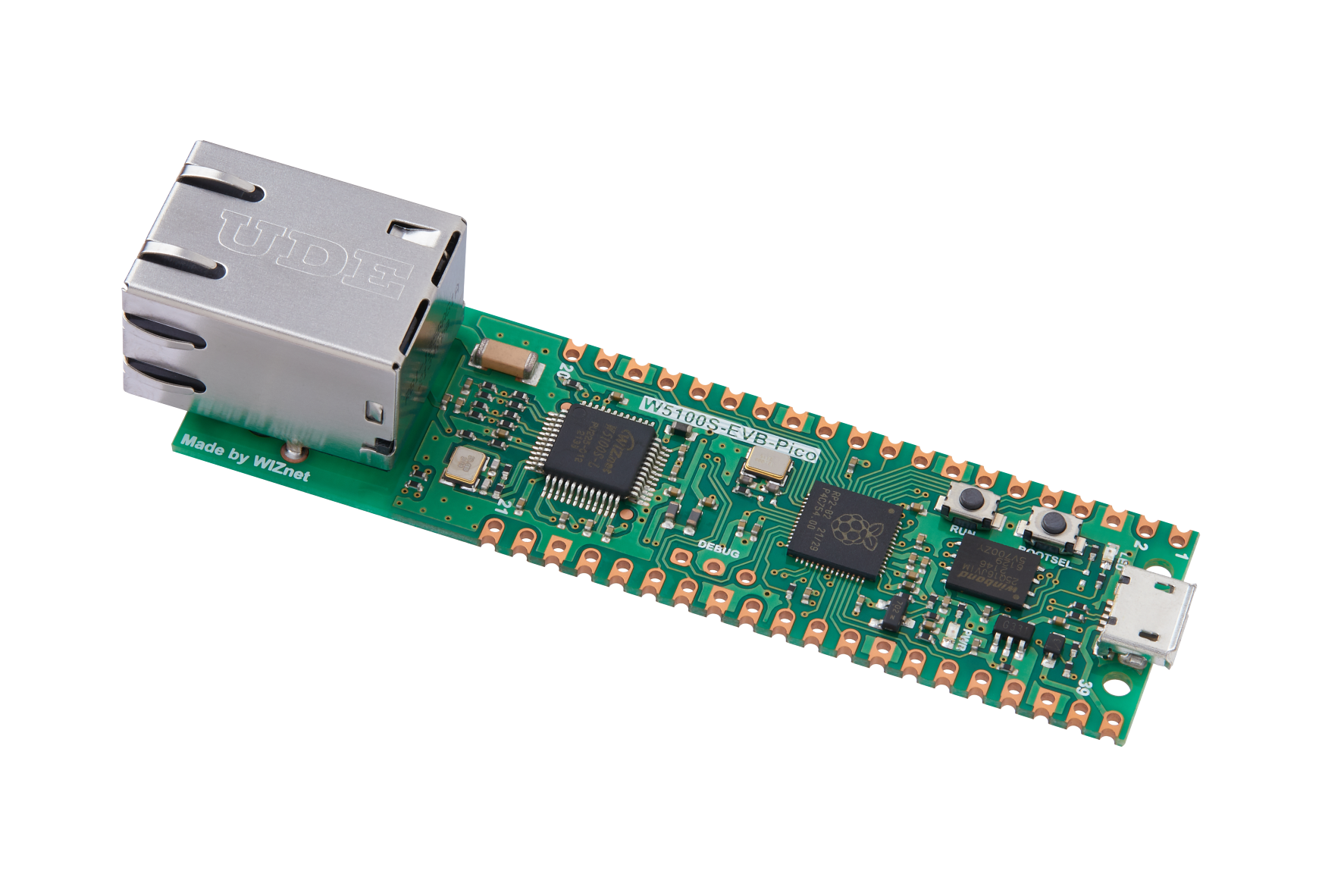
WIZnet - W5100S-EVB-Pico
x 1
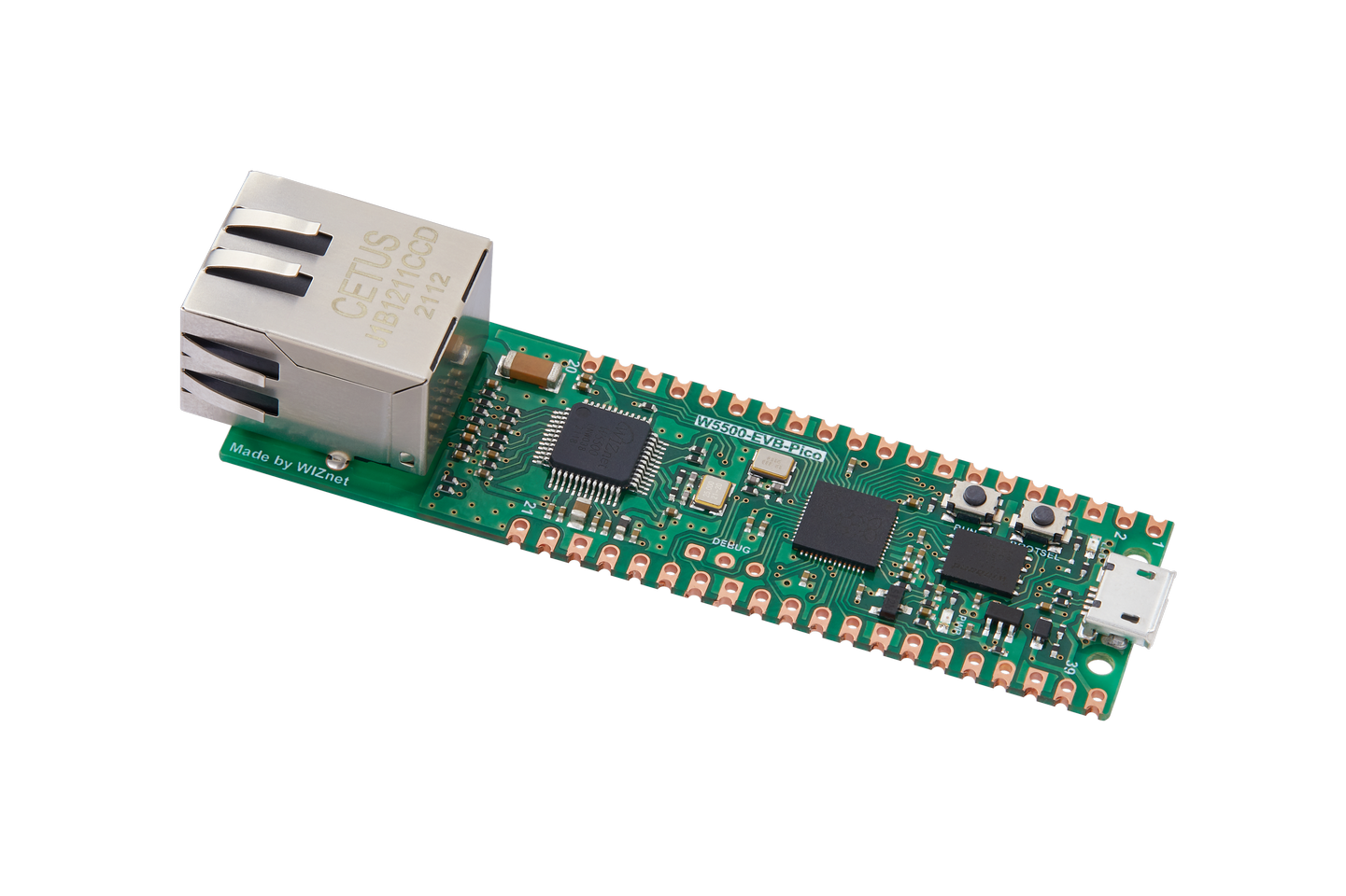
WIZnet - W5500-EVB-Pico
x 1
KiCad - KiCad
x 1
A Building-Scale LED Display, One Board at a Time
Project Lighthouse is a student initiative at Kiel University in Germany that transforms the university's tallest building into a massive LED screen. Approximately 57,000 individual LEDs installed across 392 windows (14 floors × 28 columns) create a 1,200 m² display surface where students can run games like Tetris, Pong, and Space Invaders right on the building facade.
Each window contains a "lamp" — an LED module controlled by an ATtiny841 microcontroller. These lamps receive pixel data over SPI via flat cables from a central controller board. The pico-power-board is that controller: a custom PCB designed in KiCad that serves as a motherboard for the WIZnet W5100S-EVB-Pico or W5500-EVB-Pico.
Why WIZnet Pico Boards?
The README documents a thorough evaluation of alternatives. The previous system used an ATmega/ATtiny with the Microchip ENC28J60 Ethernet controller, which proved unreliable and lacked sufficient performance and memory. The team considered STM32 chips with built-in Ethernet, but those with Ethernet support were too expensive and required a full board design. Teensy and Raspberry Pi SBCs were also ruled out on cost.
"In fact, after a lot of research we found many wireless capable microcontrollers (e.g. the official Pi Pico W and ESP32) because of the increasing popularity of the Internet of Things (IoT) but finding good and cheap Ethernet capable MCUs was difficult. Therefore we were glad that Wiznet released their Pi Pico based boards." — README.md
The W5100S-EVB-Pico and W5500-EVB-Pico offered the right balance: an RP2040 MCU with a hardware TCP/IP Ethernet controller on a compact, affordable module. The "motherboard" approach means the team only needs to design the power, protection, and distribution circuitry — the MCU and Ethernet subsystem come ready-made from WIZnet.
System Architecture
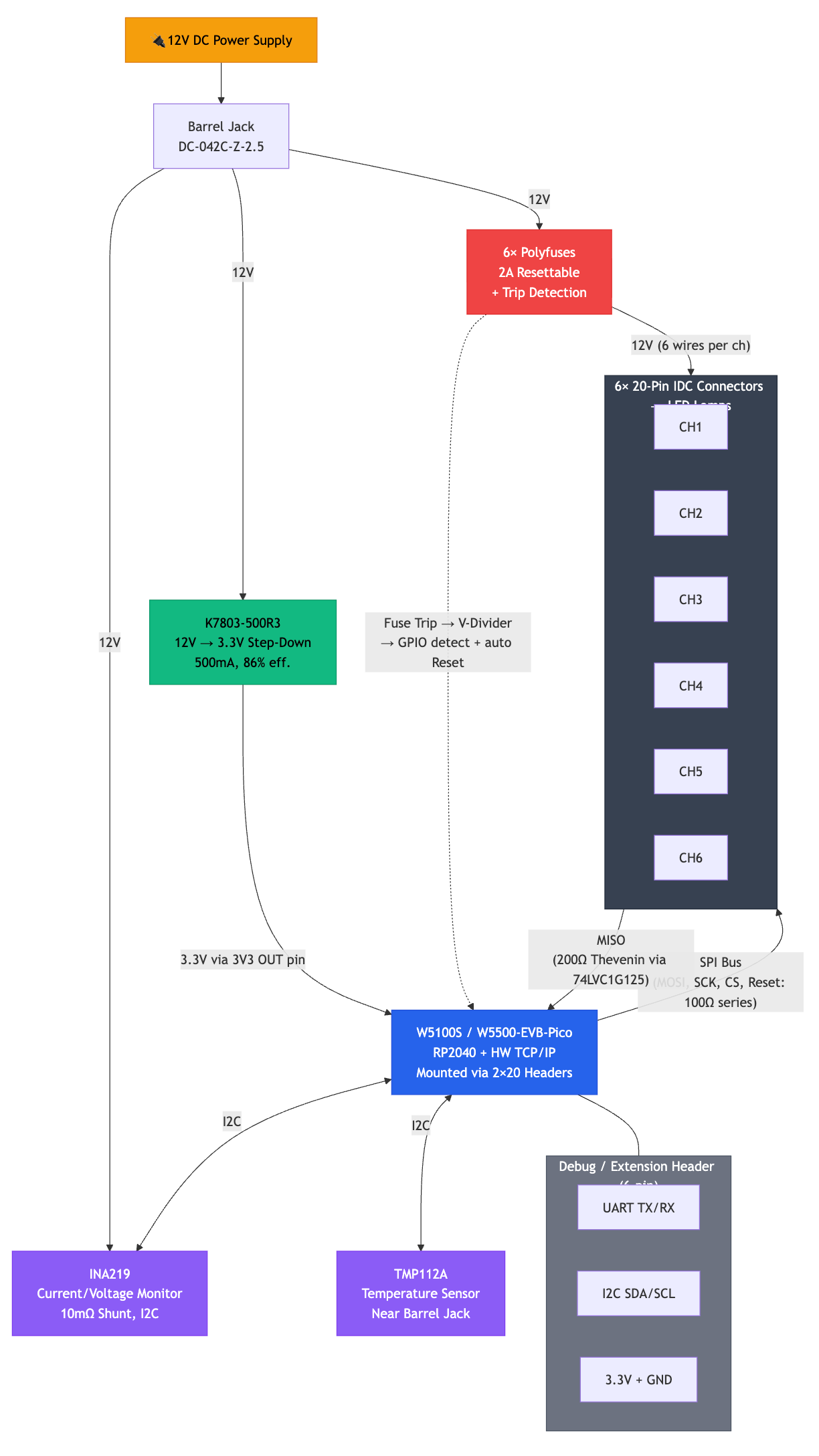
Each of the six 20-pin IDC connectors carries SPI signals (MISO, MOSI, SCK, CS), 3.3V, a Reset line, 12V power (distributed across six wires), and GND (across eight wires) to an individual lamp unit.
Power Management and Protection
The board uses a Mornsun K7803-500R3 switching regulator to step 12V down to 3.3V. This module is pin-compatible with LM78xx linear regulators but achieves up to 86% efficiency, accepting 4.75–36V input. A deliberate design choice routes 3.3V to the Pico's 3V3(OUT) pin rather than VSYS. This bypasses the Pico's internal regulator, avoiding the issue that the W5100S-EVB-Pico's linear regulator cannot efficiently handle 3.3V-to-3.3V conversion (it requires at least 1V headroom).
Each lamp channel has a 2A resettable polyfuse. If a lamp short-circuits, only that channel's fuse trips — preventing a full 10A from flowing through one lamp and creating a fire hazard. A voltage divider on the fuse output serves double duty: it feeds back to the Pico GPIO for trip detection, and it also drives the lamp's active-low reset line. This means a tripped fuse automatically resets the affected lamp without consuming an extra GPIO pin.
An INA219 current sensor with a 10 mΩ shunt monitors total power draw via I2C, and a TMP112A temperature sensor near the barrel jack tracks thermal conditions on the 12V trace.
SPI Signal Integrity over Long Cables
One of the most technically interesting aspects of this design is the signal termination strategy. SPI was never intended for long-distance communication over unshielded flat cables, and the team found significant signal integrity issues:
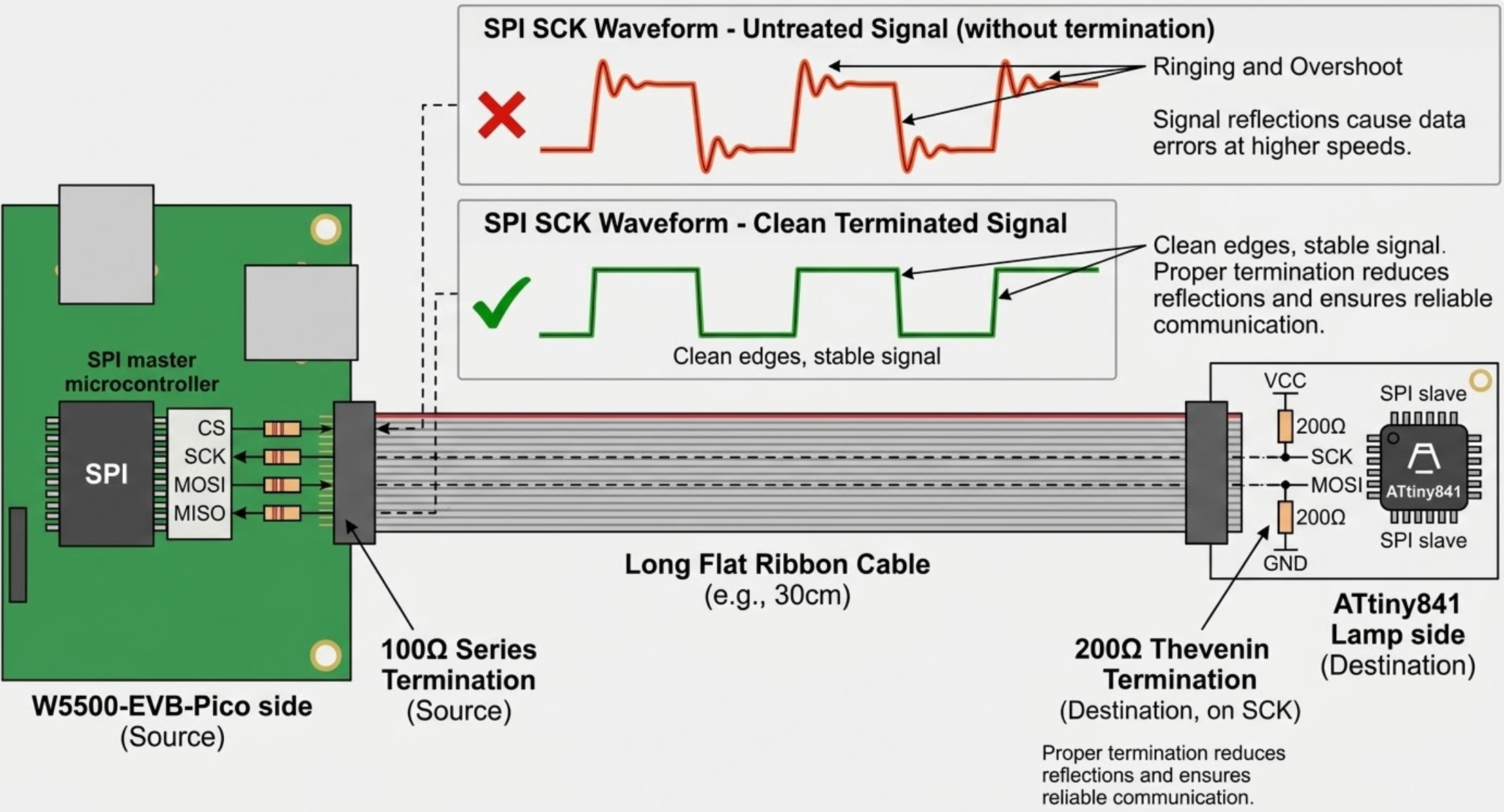
"After looking at the SPI signal with an oscilloscope, we found out that the fast switching of voltage levels causes reflections on the end of the longer cables." — README.md
The solution uses a combination of termination techniques, with resistor values determined experimentally using an oscilloscope:
Outgoing lines (SCK, MOSI, CS, Reset): 100 Ω series termination resistors at the source. This is the most common technique — the resistor absorbs reflections at the cost of slightly increased rise/fall times.
Incoming line (MISO): Initially, parallel termination was attempted, but the ATtiny841 transmitters in the lamps couldn't source enough current to reach a valid logic-high level. The team switched to Thevenin termination — two 200 Ω resistors forming a voltage divider that biases the line to Vcc/2, making it easier for the driver to swing in either direction. Each of the six MISO lines is isolated by a 74LVC1G125 tri-state buffer, allowing per-channel Thevenin termination without interference between lamps.
Design Files and BOM Overview
The KiCad project includes a complete schematic (pico-power-board.kicad_sch) and PCB layout (pico-power-board.kicad_pcb) at version 1.0. A rendered board image shows the compact layout: six IDC connectors across the top edge, the Pico mounting area in the center, the DC jack and power circuitry on the right, and the debug header at the bottom-right corner.
Key component counts from the schematic: 30× 100 Ω resistors (series termination), 12× 200 Ω resistors (Thevenin termination), 13× 10 kΩ pull-up/down resistors, 6× 27 kΩ resistors (voltage dividers for fuse detection), 9× 100 nF decoupling capacitors, and 7× polyfuses.
Limitations and Honest Assessment
This is a hardware design repository only — the firmware is being developed separately in Rust and is not publicly linked from this repo. The team acknowledges that SPI over long unshielded cables is fundamentally problematic:
"We are aware that transmitting SPI signals over long unshielded cables can and will cause interference problems." — README.md
Differential signaling with shielded cables would be ideal, but the cost and complexity of retrofitting transceiver boards on all existing lamps made it impractical. The return channel (MISO) remains the weakest link, partly due to the ATtiny841's unbuffered SPI data register.
FAQ
Q1. Can I use this board with a regular Raspberry Pi Pico (without WIZnet)?
The README mentions the Pi Pico W (Wi-Fi) as an option. The 2×20 header socket is pin-compatible with any Pico-form-factor board. However, the primary purpose is Ethernet-based control, so you would lose that capability without a WIZnet board.
Q2. Why CERN-OHL-S instead of a more common license like MIT?
CERN-OHL-S (Strongly Reciprocal) is specifically designed for open-source hardware. It's the hardware equivalent of GPL — any derivative designs must also be shared under the same license. This aligns with the academic, collaborative nature of the project.
Q3. What is the maximum power the board can handle?
The DC barrel jack is rated for 10A at 12V. Each lamp channel has a 2A polyfuse, so with six channels the theoretical maximum is 12A — but the barrel jack is the bottleneck at 10A. The 3.3V rail from the K7803-500R3 is limited to 500 mA.
Q4. Could I adapt this board for other SPI-driven LED systems?
Yes, the SPI fan-out with individual polyfuse protection and signal termination is a reusable pattern. You would need to verify the termination resistor values for your specific cable length and impedance, and potentially adjust the fuse rating for your lamp current draw.
Q5. Where is the firmware?
The firmware is being developed in Rust using the Embassy async framework, but the repository is not publicly linked from this project. The README mentions that the team initially used the C/C++ Pico SDK with WIZnet's socket API before rewriting in Rust for the W5500.