
How to Build a Zigbee Smart Switch System with W5500 Ethernet Backhaul on ESP32-C3?
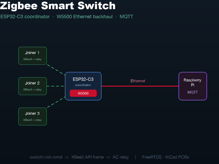
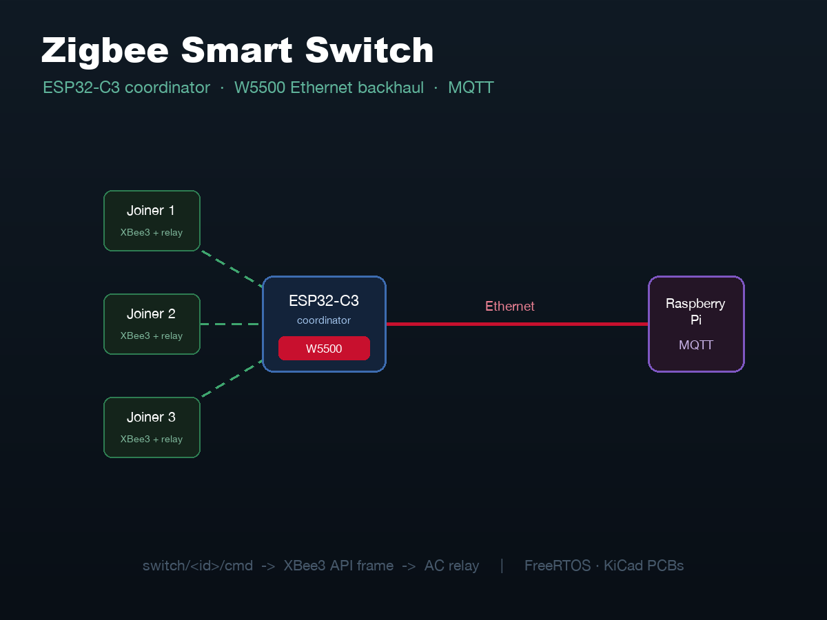
W5500 Ethernet connects an ESP32-C3 Zigbee coordinator to a Raspberry Pi MQTT broker, letting XBee3 relay nodes switch AC loads reliably without Wi-Fi.

WIZnet - W5500
x 1
SPI2 @ 20 MHz, static IP 192.168.2.10/24, direct Ethernet to Raspberry Pi MQTT broker; INT=GPIO9, RST=GPIO10
📌 Overview
Roberto Carlos Aguilar Jiménez (GitHub: RCaguilarJ) is a developer from Guadalajara, Jalisco, Mexico, and a member of the ICAMS-MMBSE academic organization. This project is a Zigbee-based smart switch system designed for remote dehumidifier control with Industry 4.0 reliability in mind. The coordinator node - an ESP32-C3 running FreeRTOS - uses a WIZnet W5500 Ethernet module to connect directly to a Raspberry Pi MQTT broker over a wired cable, while Digi XBee3 Zigbee 3.0 TH radios carry commands wirelessly to relay-equipped joiner nodes that switch AC loads.
The complete project includes coordinator firmware (ESP-IDF 6.x), joiner firmware, KiCad PCB designs for both board types, and a Docker Compose Mosquitto broker.
System Configuration
Coordinator (the W5500 node): - ESP32-C3 with FreeRTOS, four concurrent tasks - Digi XBee3 Zigbee 3.0 TH: Coordinator role, Extended PAN ID 1234, API Mode 1, UART1 (TX=IO0, RX=IO1, 115200 baud) - WIZnet W5500: SPI2 at 20 MHz, static IP 192.168.2.10/24, gateway 192.168.2.1; INT=GPIO9, RST=GPIO10; SCLK=IO5, MOSI=IO7, MISO=IO8, CS=IO6 - Physical button (IO3) for manual toggle broadcast; LED indicator (IO4) - KiCad PCB: commissioner_v1 (in progress) - Build: PlatformIO + ESP-IDF >= 6.0.0; espressif/w5500 ^1.0.1 from the Espressif component registry
Joiner (relay node): - ESP32-C3 Super Mini - Digi XBee3 Zigbee 3.0 TH: Joiner role, API Mode 1, Join Notification enabled, same PAN - Relay circuit: 2N2222A NPN transistor (low-side switch) + 1N4001 flyback diode + 5V relay; mains load switched via relay on a cut extension cord - Powered from the relay supply line; no USB required after deployment - KiCad PCB: joiner design complete, pending power specification before ordering
Broker: - Raspberry Pi running Mosquitto via Docker Compose (port 1883); eth0 set to static 192.168.2.1/24 with NetworkManager
System Architecture & Data Flow
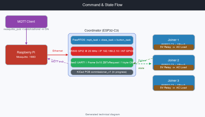
Commands flow from any MQTT client through the Raspberry Pi broker, over wired Ethernet into the W5500, and into the coordinator. The coordinator's mqtt_task receives the payload and calls relay_cmd(), which constructs a raw XBee3 API frame (Frame Type 0x10 ZBTxRequest) with a 1-byte command payload - CMD_ON=0x01, CMD_OFF=0x00, CMD_TOGGLE=0x02, CMD_POLL=0x03 - and sends it to the addressed joiner over Zigbee.
State flows in reverse: joiner nodes respond to POLL requests or physical button presses by sending a Zigbee frame back to the coordinator. The coordinator's xbee_task decodes the Frame Type 0x90 ZB RX response and calls mqtt_publish_state(node_id, state), which publishes "ON" or "OFF" to switch/<NI>/state on the broker.
FreeRTOS task layout on the coordinator:
| Task | Stack | Purpose |
|---|---|---|
xbee_task | 4096 | Continuous Zigbee frame RX and command dispatch |
button_task | 2048 | Physical button: debounce and broadcast toggle |
console_task | 4096 | UART0 debug: AT_PING, DISCOVER, RELAY, TOGGLE, POLL |
mqtt_init (no task) | - | Espressif MQTT client, event-driven |
Node discovery runs at boot via discover_nodes(), which sends an XBee ND (Node Discovery) AT command and parses the responses to build a node table (up to MAX_NODES=10 entries, keyed by 64-bit address and NI string). Duplicate ND responses are deduplicated by address.
⚙️ Role of the WIZnet W5500
The W5500 is the coordinator's sole connection to the IP network. Instead of Wi-Fi - which can suffer from congestion, interference, or association delays in industrial environments - the coordinator uses a direct point-to-point Ethernet cable to the Raspberry Pi. This gives the MQTT link a deterministic, interference-free path with no association handshake and no DHCP dependency.
// firmware/coord_esp32-c3/src/ethernet.c
eth_w5500_config_t w5500_cfg = ETH_W5500_DEFAULT_CONFIG(SPI2_HOST, &devcfg);
w5500_cfg.int_gpio_num   = W5500_INT;   // GPIO9 - hardware interrupt
phy_cfg.reset_gpio_num   = W5500_RST;  // GPIO10
// Static IP: 192.168.2.10/24, gateway 192.168.2.1
The W5500 is driven by ESP-IDF's esp_eth_mac_new_w5500 and esp_eth_phy_new_w5500 (Espressif espressif/w5500 ^1.0.1 component, ESP-IDF >= 6.0.0 required). SPI runs at 20 MHz on SPI2. The hardware interrupt pin (INT, GPIO9) lets the ESP32-C3 respond to incoming Ethernet frames efficiently without polling the SPI bus.
IP addressing is static (192.168.2.10/24) - matching the Pi's eth0 static IP (192.168.2.1) - so the two devices form a self-contained wired subnet with no router or DHCP server needed.
Where It Fits - Value and Limits
Good fits: - Industrial or building automation where a Raspberry Pi controller needs deterministic Ethernet backhaul to a wireless sensor/actuator mesh - RF-noisy environments (factory floors, warehouses) where Wi-Fi is unreliable - Learning projects combining ESP-IDF W5500 Ethernet with Zigbee in a multi-node FreeRTOS architecture - Makers who want to extend Zigbee reach with a Pi-based MQTT hub instead of a commercial gateway
Current limits: - DHCP is disabled; the system requires a manually configured direct cable between coordinator and Pi - The MQTT handler currently routes all commands to all nodes regardless of the target topic (switch/1/cmd also broadcasts to ALL). Per-node addressing is partially implemented but not complete. - Humidity-threshold automation (the original project goal) is on the roadmap, not yet implemented - Joiner PCB ordering is pending a power specification confirmation; must be assembled manually in the meantime - Coordinator PCB (commissioner_v1) is still a work in progress in KiCad - Maximum 10 joiner nodes (MAX_NODES in config.h) - Requires ESP-IDF >= 6.0.0 for the W5500 component
Related WIZnet Maker Projects
Artnet to Zigbee Bridge for ESP32 C6 and W5500 (Grade B) receives ArtNet DMX lighting data over a W5500 Ethernet interface and converts it to Zigbee commands for wireless light nodes. Both projects wire W5500 as the Ethernet interface in a hybrid Ethernet-plus-Zigbee system, with the MCU bridging between IP and Zigbee radio. The protocol stacks diverge at both ends: that project receives unidirectional ArtNet universe streams and uses the ESP32-C6's native Zigbee stack via the ESP-Zigbee SDK; this project exchanges MQTT messages bidirectionally and builds raw XBee3 API frames (Frame Type 0x10 ZBTxRequest) manually in C with no third-party Zigbee library.
Why W5500 in ESP32-S3 Zigbee Gateway? (Unofficial Firmware) (Grade A) is a W5500-equipped ESP32-S3 board running upstream Zigbee coordinator firmware - a hardware platform post that makes the case for W5500 as natural Ethernet backhaul for a Zigbee coordinator. Both projects share the W5500-plus-Zigbee coordinator topology and the same rationale for wired Ethernet over Wi-Fi. This project goes further in firmware depth: coordinator logic (XBee3 frame parsing, node discovery via XBee ND, per-node relay state tracking, MQTT topic routing) is built from scratch in C under FreeRTOS with four concurrent tasks, and KiCad PCB designs cover both coordinator and joiner boards.
W5500 Module + Zigbee Gateway (Grade A) is an earlier W5500-plus-Zigbee gateway built on a CC2530 Zigbee SoC running Texas Instruments Z-Stack firmware over UART. Both projects use W5500 for Ethernet in a Zigbee gateway. This project carries the same topology forward onto ESP32-C3 and ESP-IDF 6.x: SPI-driven W5500 at 20 MHz via the espressif/w5500 ^1.0.1 component, custom XBee3 API frame code replacing Z-Stack UART, and a FreeRTOS four-task architecture replacing a single-loop design. Together the two projects show the same gateway pattern across a hardware generation.
What this project uniquely contributes is the complete, custom-built relay chain: raw XBee3 API frame construction and parsing (no Zigbee SDK), bidirectional MQTT control with per-node state feedback, interrupt-driven W5500 receive (INT on GPIO9), FreeRTOS four-task scheduling, and KiCad PCBs for both coordinator and joiner - all in one repository.
❓ FAQ
Q. Why use W5500 wired Ethernet instead of the ESP32-C3's built-in Wi-Fi for the coordinator-to-Pi link? A direct Ethernet cable provides a deterministic, interference-free MQTT path in environments where Wi-Fi can suffer from congestion or RF noise. The static IP setup also eliminates DHCP dependency, making the coordinator-to-Pi link self-contained and reliable even without a router.
Q. How are commands sent to Zigbee nodes? The coordinator builds raw XBee3 API frames manually in C. A Frame Type 0x10 ZBTxRequest carries a 1-byte command payload (CMD_ON=0x01, CMD_OFF=0x00, CMD_TOGGLE=0x02, CMD_POLL=0x03) addressed to a specific 64-bit joiner address or the broadcast address. No third-party Zigbee library is used; the frame structure follows the Digi XBee3 API specification directly.
Q. Can additional joiner nodes be added to the network? Yes, up to MAX_NODES (10, set in config.h). New joiners join the Zigbee network automatically at power-up. At boot, discover_nodes() runs an XBee ND scan and populates a node table with each joiner's 64-bit address and NI string. Duplicate ND responses are filtered automatically.
Q. What MQTT topics does the system use? switch/all/cmd broadcasts to all nodes; switch/1/cmd targets node index 1; switch/<NI>/state carries each joiner's reported relay state back to the broker. Supported commands are ON, OFF, TOGGLE, and POLL.
Q. Is this project ready for production use? Not yet. The joiner PCB is pending a power spec, the coordinator PCB is in progress, and humidity-threshold automation is on the roadmap. It is a working firmware prototype - demonstrated with wired-up components - and is best suited for development, learning, and small-scale pilot use.
한국어 (Korean)
📌 개요
Roberto Carlos Aguilar Jiménez (GitHub: RCaguilarJ)는 멕시코 과달라하라 출신의 개발자로, ICAMS-MMBSE 아카데믹 조직의 멤버입니다. 이 프로젝트는 Industry 4.0 신뢰성을 목표로 설계된 Zigbee 기반 스마트 스위치 시스템으로, 원격 습도 제거기 제어를 목적으로 합니다. 코디네이터 노드(FreeRTOS를 실행하는 ESP32-C3)는 WIZnet W5500 이더넷 모듈로 Raspberry Pi MQTT 브로커에 유선 직접 연결하고, Digi XBee3 Zigbee 3.0 TH 라디오로 릴레이 장착 조이너 노드에 명령을 무선으로 전달해 AC 부하를 제어합니다.
전체 프로젝트에는 코디네이터 펌웨어(ESP-IDF 6.x), 조이너 펌웨어, 양쪽 보드의 KiCad PCB 설계, Docker Compose Mosquitto 브로커가 포함됩니다.
시스템 구성
코디네이터 (W5500 노드): - ESP32-C3, FreeRTOS 4개 동시 태스크 - XBee3 Zigbee 3.0 TH: 코디네이터 역할, Extended PAN ID 1234, API 모드 1, UART1 (TX=IO0, RX=IO1, 115200 baud) - WIZnet W5500: SPI2 @ 20MHz, 정적 IP 192.168.2.10/24, 게이트웨이 192.168.2.1; INT=GPIO9, RST=GPIO10; SCLK=IO5, MOSI=IO7, MISO=IO8, CS=IO6 - KiCad PCB: commissioner_v1 (설계 진행 중) - 빌드: PlatformIO + ESP-IDF >= 6.0.0; espressif/w5500 ^1.0.1
조이너 (릴레이 노드): - ESP32-C3 Super Mini - XBee3 Zigbee 3.0 TH: 조이너 역할, API 모드 1, 조인 알림 활성화 - 릴레이 회로: 2N2222A NPN 트랜지스터 + 1N4001 환류 다이오드 + 5V 릴레이; 연장 코드로 AC 부하 제어 - 릴레이 공급 라인으로 전원 공급 (배포 후 USB 불필요) - KiCad PCB: 설계 완료, 전원 사양 확인 후 발주 예정
시스템 아키텍처와 데이터 흐름
MQTT 클라이언트의 명령이 Raspberry Pi 브로커를 거쳐 유선 이더넷으로 W5500에 전달되고 코디네이터로 들어옵니다. 코디네이터의 mqtt_task가 페이로드를 수신해 relay_cmd()를 호출하면, 1바이트 명령 페이로드를 담은 XBee3 API 프레임(Frame Type 0x10 ZBTxRequest)이 Zigbee로 조이너에 전송됩니다.
상태는 역방향으로 전달됩니다. 조이너는 POLL 요청이나 물리적 버튼 입력에 응답해 Zigbee 프레임을 코디네이터로 보내고, 코디네이터는 switch/<NI>/state에 "ON" 또는 "OFF"를 발행합니다.
⚙️ WIZnet W5500의 역할
W5500은 코디네이터와 IP 네트워크 간의 유일한 연결 수단입니다. Wi-Fi 대신 Raspberry Pi와 직접 이더넷 케이블로 연결함으로써, 혼잡하거나 RF 잡음이 많은 환경에서도 MQTT 링크에 결정론적이고 간섭 없는 경로를 보장합니다.
W5500은 ESP-IDF의 esp_eth_mac_new_w5500 / esp_eth_phy_new_w5500 드라이버(Espressif espressif/w5500 ^1.0.1 컴포넌트, ESP-IDF >= 6.0.0 필요)로 SPI2에서 20MHz로 구동됩니다. 하드웨어 인터럽트 핀(INT, GPIO9)을 사용해 SPI 버스 폴링 없이 효율적으로 이더넷 프레임을 수신합니다.
IP는 정적 구성(192.168.2.10/24, 게이트웨이 192.168.2.1)으로, DHCP 서버나 라우터 없이 코디네이터와 Pi가 독립적인 유선 서브넷을 형성합니다.
적합한 사용 사례와 한계
적합한 경우: - Raspberry Pi 기반 컨트롤러에서 무선 메시로의 결정론적 이더넷 백홀이 필요한 산업/빌딩 자동화 - Wi-Fi가 불안정한 RF 잡음 환경(공장, 창고) - ESP-IDF W5500 이더넷과 Zigbee를 FreeRTOS 멀티노드 시스템에서 결합하는 학습 프로젝트
현재 한계: - DHCP 비활성화: 코디네이터와 Pi 간 수동 설정된 직접 케이블 필요 - MQTT 핸들러가 현재 모든 명령을 ALL 노드로 라우팅 (개별 노드 주소 지정 미완성) - 습도 임계값 자동화는 로드맵 단계 - 조이너 PCB는 전원 사양 확인 대기 중 - 코디네이터 PCB는 KiCad 설계 진행 중 - 최대 10개 조이너 노드 (MAX_NODES) - ESP-IDF >= 6.0.0 필요
관련 WIZnet Maker 프로젝트
Artnet to Zigbee Bridge for ESP32 C6 and W5500 (Grade B) - W5500 이더넷으로 ArtNet DMX 조명 데이터를 수신해 Zigbee 명령으로 변환, 무선 조명 노드에 전달하는 프로젝트입니다. 두 프로젝트 모두 W5500을 이더넷-Zigbee 하이브리드 시스템의 유선 인터페이스로 쓰고 MCU가 IP와 Zigbee 라디오 사이를 브리지합니다. 프로토콜 스택은 양쪽 끝에서 갈립니다. 그 프로젝트는 단방향 ArtNet 유니버스 스트림을 수신하고 ESP32-C6 내장 Zigbee 스택(ESP-Zigbee SDK)을 씁니다. 이 프로젝트는 MQTT로 양방향 통신하고 서드파티 Zigbee 라이브러리 없이 C로 XBee3 API 프레임(Frame Type 0x10 ZBTxRequest)을 직접 생성합니다.
Why W5500 in ESP32-S3 Zigbee Gateway? (Unofficial Firmware) (Grade A) - W5500을 탑재한 ESP32-S3 보드에 업스트림 Zigbee 코디네이터 펌웨어를 올린 하드웨어 플랫폼 포스트로, Zigbee 코디네이터 이더넷 백홀로서의 W5500의 당위성을 보여줍니다. 두 프로젝트 모두 W5500+Zigbee 코디네이터 토폴로지와 유선 이더넷을 선택한 이유가 같습니다. 이 프로젝트는 펌웨어 깊이를 더합니다. 코디네이터 로직(XBee3 프레임 파싱, XBee ND 노드 탐색, 노드별 릴레이 상태 추적, MQTT 토픽 라우팅)을 FreeRTOS 4-태스크 구조에서 C로 처음부터 직접 구현하고, 코디네이터·조이너 양쪽 KiCad PCB 설계를 포함합니다.
W5500 Module + Zigbee Gateway (Grade A) - CC2530 Zigbee SoC에서 TI Z-Stack 펌웨어를 UART로 돌리는 초기 W5500+Zigbee 게이트웨이 설계입니다. 두 프로젝트 모두 Zigbee 게이트웨이의 이더넷 연결에 W5500을 씁니다. 이 프로젝트는 같은 토폴로지를 ESP32-C3·ESP-IDF 6.x로 현대화합니다. espressif/w5500 ^1.0.1로 20MHz SPI 구동, Z-Stack UART 대신 직접 작성한 XBee3 API 프레임 코드, 단일 루프 대신 FreeRTOS 4-태스크 구조. 두 프로젝트를 같이 보면 한 세대를 사이에 둔 같은 게이트웨이 패턴의 진화를 볼 수 있습니다.
이 프로젝트만의 고유한 기여: Zigbee SDK 없이 C로 직접 작성한 XBee3 API 프레임 생성·파싱, 노드별 상태 피드백을 갖춘 양방향 MQTT 제어, 인터럽트 기반 W5500 수신(INT GPIO9), FreeRTOS 4-태스크 스케줄링, 코디네이터·조이너 양쪽 KiCad PCB - 이 모든 것이 하나의 저장소에 있습니다.
❓ FAQ
코디네이터-Pi 링크에 ESP32-C3 내장 Wi-Fi 대신 W5500 유선 이더넷을 사용하는 이유는? 직접 이더넷 케이블은 Wi-Fi 혼잡이나 RF 간섭이 발생할 수 있는 환경에서 MQTT 트래픽에 더 결정론적이고 안정적인 경로를 제공합니다. 정적 IP 구성으로 DHCP 의존성을 제거해 라우터 없이도 동작하는 독립 서브넷을 구성합니다.
Zigbee 노드에 명령을 어떻게 전송하나요? 코디네이터가 C 코드로 XBee3 API 프레임을 직접 생성합니다. Frame Type 0x10 ZBTxRequest에 1바이트 명령 페이로드(CMD_ON=0x01, CMD_OFF=0x00, CMD_TOGGLE=0x02, CMD_POLL=0x03)를 담아 특정 조이너 주소 또는 브로드캐스트 주소로 전송합니다.
조이너 노드를 더 추가할 수 있나요? 네, config.h의 MAX_NODES(기본값 10)까지 가능합니다. 새 조이너는 전원 투입 시 자동으로 Zigbee 네트워크에 연결되고, 부팅 시 discover_nodes()의 XBee ND 스캔으로 노드 테이블에 등록됩니다.
시스템이 사용하는 MQTT 토픽은 무엇인가요? switch/all/cmd는 모든 노드에 브로드캐스트, switch/1/cmd는 인덱스 1 노드 대상, switch/
이 프로젝트를 프로덕션에 사용할 수 있나요? 아직 아닙니다. 조이너 PCB는 전원 사양 확인 대기 중이고, 코디네이터 PCB는 진행 중이며, 습도 임계값 자동화는 로드맵 단계입니다. 컴포넌트를 연결한 동작 펌웨어 프로토타입으로, 개발 및 소규모 파일럿에 적합합니다.
-
Source Code (GitHub)
Full coordinator + joiner firmware (ESP-IDF 6.x), KiCad PCBs, Docker Compose Mosquitto

-
Espressif W5500 ESP-IDF Component
espressif/w5500 ^1.0.1 - W5500 driver used in idf_component.yml
-
ESP-IDF Ethernet API (ESP32-C3)
ESP-IDF Ethernet driver documentation for W5500 integration
-
Digi XBee3 API Frame Reference
XBee3 API frame types used in firmware (0x10 ZBTxRequest, 0x90 ZBRx, 0x08 AT)
-
WIZnet W5500 Product Page
W5500 product overview and datasheet