
2040-ArtNode: RP2040 + W5500 ArtNet LED Controller Board
Open-source KiCad PCB design for a 4-universe ArtNet LED controller with RP2040, W5500, USB-C charging, and JLCPCB assembly support

Raspberry Pi - RP2040
x 1

WIZnet - W5500
x 1
KiCad - KiCad
x 1
Python - Python
x 1
An ArtNet Controller Designed for Manufacturing
Dan Newcome, a maker based in the USA, has published a complete open-source PCB design for an ArtNet LED controller built around the RP2040 and WIZnet W5500. Unlike most maker ArtNet projects that wire up an existing W5500-EVB-Pico on a breadboard or stripboard, this one is a custom board designed from the ground up for JLCPCB turnkey assembly. Every component in the BOM comes from the JLCPCB/LCSC catalog with matching part numbers, so you can order fully assembled boards without sourcing any parts yourself.
The board drives four independent WS2812B / SK6812 LED universes over Ethernet using the ArtNet protocol (UDP port 6454), with a total capacity of 1,024 pixels (256 per universe at 30fps).
What Is ArtNet?
ArtNet is a protocol for transmitting DMX512 lighting data over Ethernet as UDP packets on port 6454. Originally designed for professional stage lighting, it has become widely adopted in the LED maker community for controlling large pixel installations. Each ArtNet "universe" carries 512 channels (170 RGB pixels). By supporting four universes on a single board, this controller can address up to 680 RGB pixels, or 1,024 with reduced channel depth.
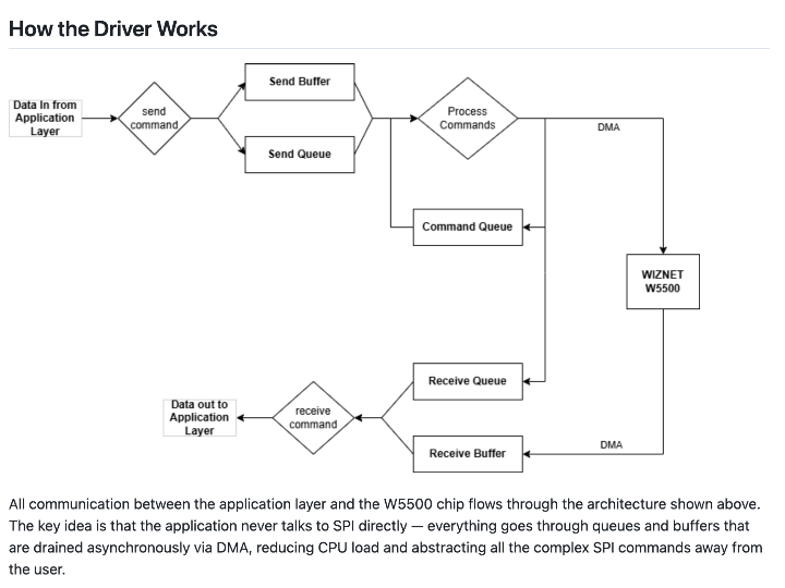
The W5500 handles the UDP reception in hardware through its built-in TCP/IP stack (TOE). The RP2040 only needs to parse the ArtNet packet headers and route pixel data to the correct PIO state machine. This offloading is especially valuable for real-time LED control, where the MCU needs to spend its cycles on precise signal timing rather than network protocol processing.
Power Architecture
One of the more thoughtful aspects of this design is the dual-source power system. The board runs from USB-C (5V/3A) or a single-cell LiPo battery, with automatic switching:
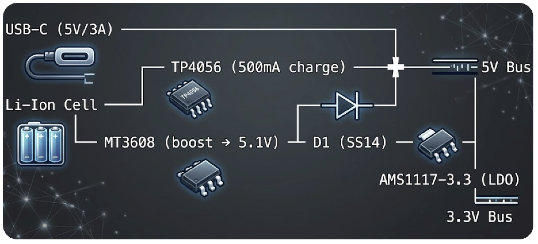
When USB-C is connected, the TP4056 charges the battery while the board runs simultaneously. On battery only, the MT3608 boost converter maintains the 5V rail. A Schottky diode (SS14) prevents back-feeding between the two sources.
An important note from the design: the board provides only the LED control signal and a pass-through 5V pin on each output connector. At full white brightness, 1,024 WS2812B pixels draw up to 61A at 5V, which must come from external power supplies connected directly to the LED strips. The board itself draws about 300mA for its own electronics.
Board Layout and Pin Assignment
The design fits everything into a compact 100mm x 70mm, 2-layer FR4 board with ENIG surface finish. The RP2040's GPIO allocation is straightforward:
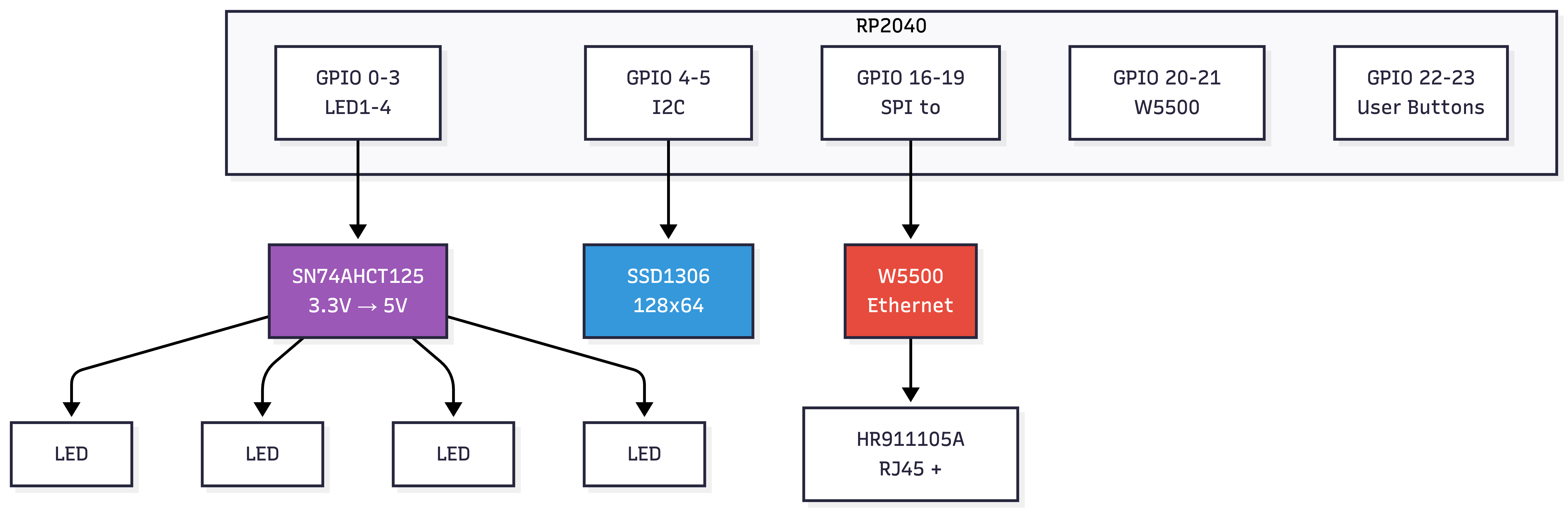
The SN74AHCT125 quad buffer handles level shifting on all four LED data lines. WS2812B LEDs expect 5V logic, but the RP2040 outputs 3.3V. Many projects skip this step and rely on the LEDs' tolerance, which works for short runs but causes flickering on longer strips. This board uses a proper level shifter for reliable signal margins.
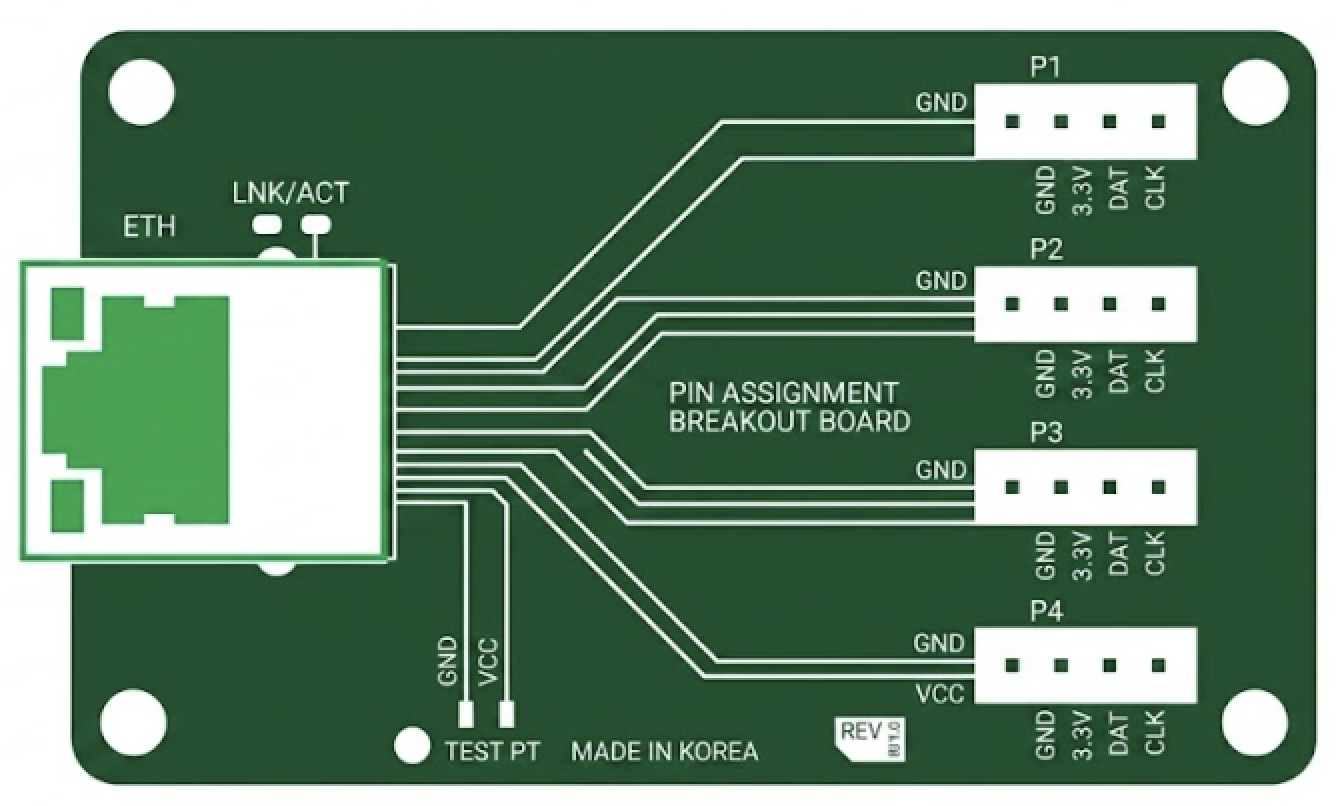
Each LED output connector (J5 through J8) is a 3-pin 2.54mm header: GND, DATA (5V level), and VCC5V. For production use with many pixels, you would inject external 5V power directly into the strips and use only the DATA and GND pins from the board.
Python-Generated KiCad Files
An unusual aspect of this project: all design files are generated by Python scripts rather than edited manually in the KiCad GUI. The repository contains four generators:
| Script | Output |
|---|---|
gen_schematic.py | artnet-led-controller.kicad_sch |
gen_pcb.py | artnet-led-controller.kicad_pcb |
gen_project.py | artnet-led-controller.kicad_pro |
gen_bom.py | jlcpcb-bom.csv |
This approach makes the entire hardware design version-controllable and reproducible. Instead of tracking hard-to-diff KiCad XML files, you review changes in clean Python code. It also makes it easy to parameterize the design for variations.
The schematic is self-contained with all symbols defined inline, so it opens in KiCad 7 without any external library dependencies. The PCB has all components placed with GND copper pours defined on both layers. To finish, you need to run "Update PCB from Schematic" in KiCad and then route the tracks.
JLCPCB Assembly
The BOM is organized for direct JLCPCB upload. Most parts are JLCPCB "Basic" (no extra fee). Four components are "Extended" parts with a one-time $3 setup fee each:
| Part | LCSC | Fee |
|---|---|---|
| W25Q16JVSSIQ (Flash) | C97521 | $3 |
| W5500 | C32646 | $3 |
| USB4125-GF-A (USB-C) | C165948 | $3 |
| HR911105A (RJ45) | C12074 | $3 |
Total extended part fees are approximately $12 per order. All other components are Basic parts.
Firmware (Not Included)
The repository contains only the hardware design. The README suggests three firmware approaches:
- Arduino-Pico + Ethernet library: W5500 support built in, easiest ArtNet path
- pico-sdk + LWIP: full control, lower overhead
- MicroPython: W5500 NIC driver included since v1.20
The firmware task is to listen on UDP port 6454, parse ArtDMX packets, and route universes 0 through 3 to GPIO 0 through 3 via the RP2040's PIO WS2812 driver. Programming is done via UF2 drag-and-drop over USB-C, or SWD debug through the J10 header.
For a complete working ArtNet node firmware reference using the same W5500 + RP2040 combination, see the Instructables build by UltraW3ird which uses the W5500-EVB-Pico with a full Arduino sketch.
FAQ
Q: What is ArtNet and how does it work with W5500?
A: ArtNet transmits DMX512 lighting data as UDP packets on port 6454 over Ethernet. The W5500 receives these packets using its hardware TCP/IP stack (TOE), so the RP2040 only handles application-level parsing. Each universe carries 512 channels, enough for 170 RGB pixels.
Q: Can I order this board fully assembled from JLCPCB?
A: Yes. The BOM uses only JLCPCB/LCSC catalog parts with matching part numbers. Four "Extended" parts incur a one-time $3 fee each (about $12 total). Upload the gerbers, BOM CSV, and pick-and-place file to JLCPCB for turnkey assembly.
Q: Why generate KiCad files with Python instead of editing them directly?
A: This makes the design fully version-controllable and reproducible. Changes are tracked in readable Python code rather than hard-to-diff KiCad XML. It also enables parameterized design variations.
Q: How does this compare to using a W5500-EVB-Pico dev board?
A: A W5500-EVB-Pico works well for prototyping, but this custom board integrates USB-C LiPo charging, a boost converter, proper level shifting, an OLED header, and user buttons into a single 100x70mm PCB designed for production assembly.
-
KiCad 7, all symbols inline
