
Modular HMI
Low-cost HMI for industrial systems. Interface with ModbusTCP. Uses MicroPython for easy on-site modifications with heads-up LCD.

WIZnet - W55RP20
x 1
micropython - MicroPython
x 1
Introduction
The project involves modular and low-cost HMI system add-on for industrial control systems applications via the use of LCD display. We can interface to many industrial protocols such as Modbus TCP. The application uses MicroPython to modify elements of the HMI display graphics to allow easy modification by different on-site engineers.
The demonstration uses the WIZnet ioNIC W55RP20 for a reduced BOM cost. This uses the System in Package (SiP) technology. The WIZnet ioNIC W55RP20 is a combination of the Raspberry Pi RP2040 and WIZnet W5500 Ethernet controller into a single chip.
Project Aim
We will interface to an existing industrial system over Modbus TCP on the address 192.168.77.55.
Hardware Setup
The hardware unboxing is a simple box with the W55RP20-EVB-PICO (evaluation board for W55RP20).
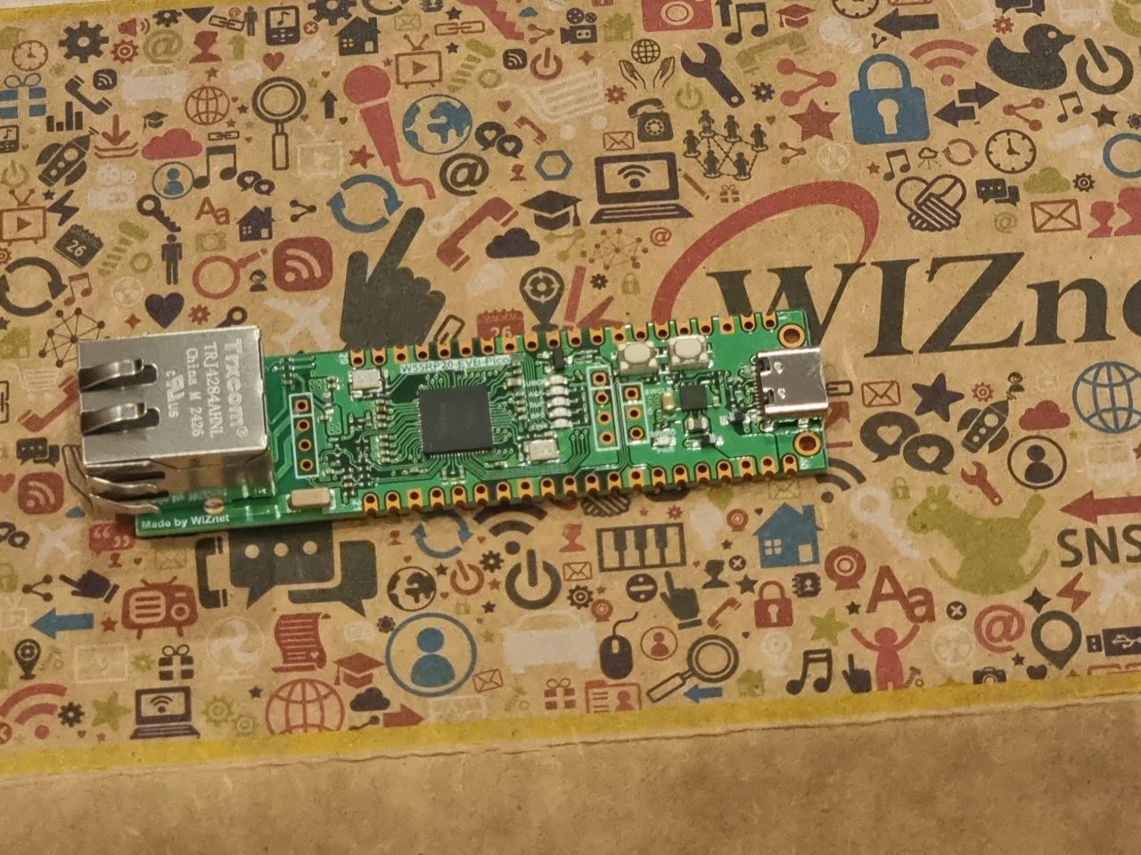
The documentations of the board are found here, including the pinout of the board.
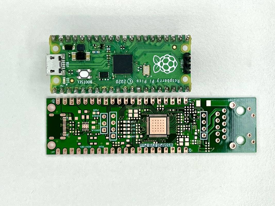
It has the same footprint but slightly longer to accommodate the Ethernet port. This is a comparison. [Photo as shown from the WIZnet LinkedIn post]
Firmware Setup
Download the MicroPython firmware from here. This is the ioNIC version with built-in drivers for the network.
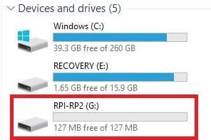
Unzip the folder and choose the .uf2 binary file. We will upload the firmware by holding down the BOOTSEL button and reset the device using RUN button. This will put the RP2040 into bootloader mode and a UF2 drive will appear on your computer. Drag and drop the MicroPython firmware into the drive.
Next, I installed the Thonny IDE to modify the running code.
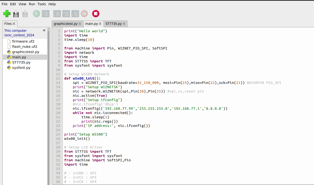
Application Code
1. Network Connectivity
The first demo is to test the network connection. The example code is found here: https://github.com/WIZnet-ioNIC/WIZnet-ioNIC-micropython/blob/master/WIZnet-ioNIC_examples/dhcp.py
from machine import Pin,WIZNET_PIO_SPI
import network
import time

def w5x00_init():
   spi = WIZNET_PIO_SPI(baudrate=31_250_000, mosi=Pin(23),miso=Pin(22),sck=Pin(21)) #W55RP20 PIO_SPI
   print("Setup WIZNET5K")
   nic = network.WIZNET5K(spi,Pin(20),Pin(25)) #spi,cs,reset pin
   nic.active(True)
   print("Setup ifconfig")
   #nic.ifconfig('dhcp')
   nic.ifconfig(('192.168.77.99','255.255.255.0','192.168.77.1','8.8.8.8'))
   while not nic.isconnected():
       time.sleep(1)
       print(nic.regs())
   print('IP address:', nic.ifconfig())

w5x00_init()
On my computer I confirm that I can ping the ioNIC board.
$ ping 192.168.77.99
PING 192.168.77.99 (192.168.77.99) 56(84) bytes of data.
64 bytes from 192.168.77.99: icmp_seq=1 ttl=255 time=108 ms
64 bytes from 192.168.77.99: icmp_seq=2 ttl=255 time=31.5 ms
64 bytes from 192.168.77.99: icmp_seq=3 ttl=255 time=52.4 ms
64 bytes from 192.168.77.99: icmp_seq=4 ttl=255 time=10.3 ms
64 bytes from 192.168.77.99: icmp_seq=5 ttl=255 time=32.6 ms
2. Modbus TCP Library
Next I used the mpremote tool to install the micropython-modbus library onto the board.
$ mpremote mip install 'github:brainelectronics/micropython-modbus'
   Install github:brainelectronics/micropython-modbus
   Installing github:brainelectronics/micropython-modbus/package.json to /lib
   Installing: /lib/umodbus/__init__.py
   Installing: /lib/umodbus/common.py
   Installing: /lib/umodbus/const.py
   Installing: /lib/umodbus/functions.py
   Installing: /lib/umodbus/modbus.py
   Installing: /lib/umodbus/serial.py
   Installing: /lib/umodbus/tcp.py
   Installing: /lib/umodbus/typing.py
   Installing: /lib/umodbus/version.py
   Done
This is the example code to read from a Modbus slave.
from umodbus.tcp import TCP as ModbusTCPMaster
print("Starting Modbus Master")
tcp_device = ModbusTCPMaster(
slave_ip='192.168.77.55',
slave_port=502,
timeout=10
)
while True:
time.sleep(1)
coil_status = tcp_device.read_coils(
slave_addr=1,
starting_addr=0,
coil_qty=8)
print('Status of coil', coil_status)
input_status = tcp_device.read_discrete_inputs(
slave_addr=1,
starting_addr=0,
input_qty=8)
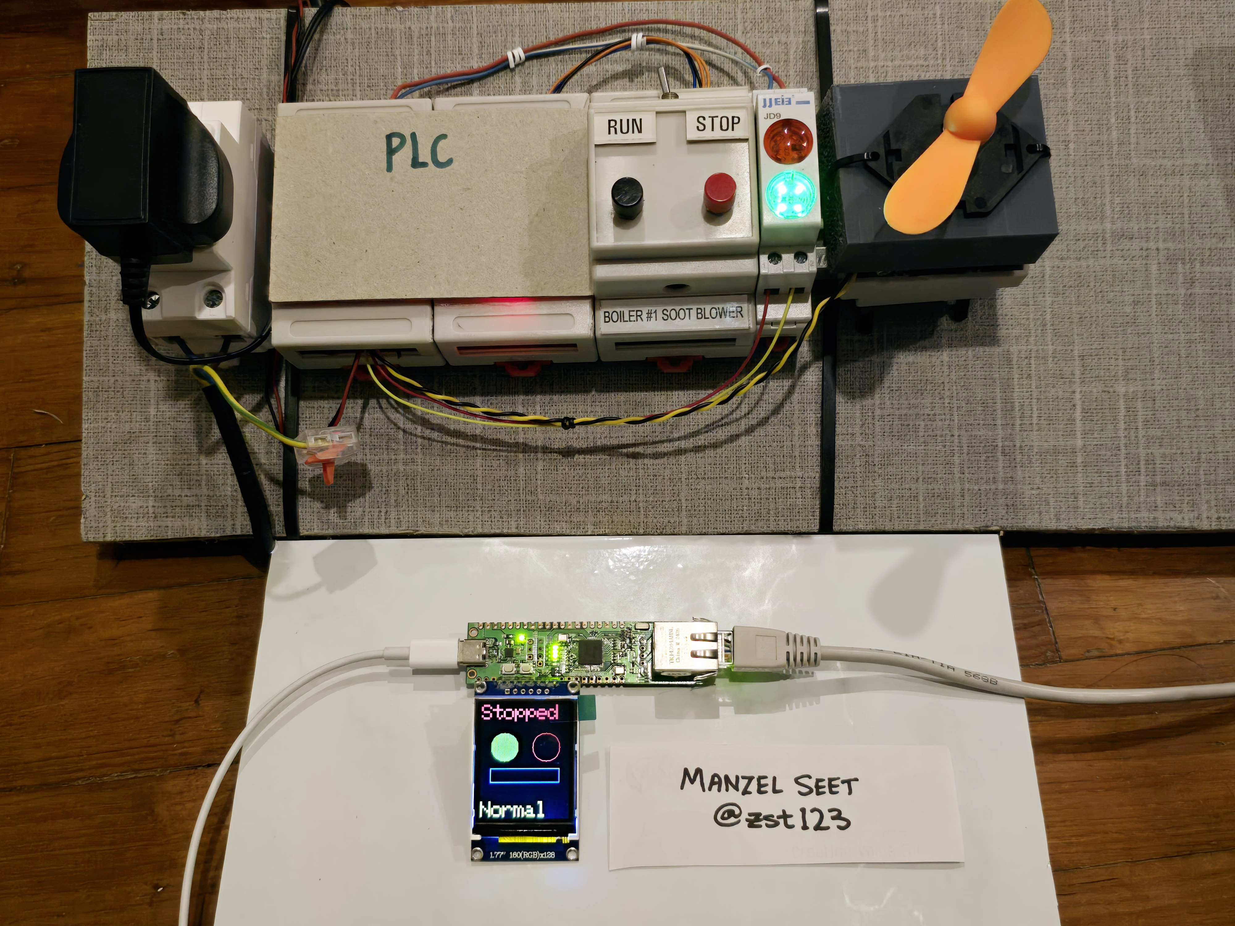
print('Status of inputs', coil_status)I have a PLC running on address 192.168.77.55 and I am able to see the coil and input status update in real-time.
IP address: ('192.168.77.99', '255.255.255.0', '192.168.77.1', '8.8.8.8')
Starting Modbus Master
Status of coil [False, False, False, False, False, False, True, False]
Status of inputs [False, False, False, False, False, False, False, False]
(...)
Status of coil [False, False, True, False, False, True, False, True]
Status of inputs [False, False, False, False, False, True, False, False]
I wrote this code to look up the values and print it more readably. Take note that the modbus library forms the array in reverse direction, hence I used indexing from the back
   alarm_status = input_status[-2-1]
   running_status = coil_status[-5-1]
   motor_status = coil_status[-2-1]
   green_led = coil_status[-1-1]
   red_led = coil_status[-0-1]
   print(f"ALARM: {alarm_status*1} | RUNNING: {running_status*1} | MOTOR: {motor_status*1} | RED LED: {red_led*1} | GREEN LED: {green_led*1}")
Output looks like this
   IP address: ('192.168.77.99', '255.255.255.0', '192.168.77.1', '8.8.8.8')
   Starting Modbus Master
   ALARM: 0 | RUNNING: 0 | MOTOR: 0 | RED LED: 0 | GREEN LED: 1
   ALARM: 0 | RUNNING: 0 | MOTOR: 0 | RED LED: 0 | GREEN LED: 1
   ...
3. TFT LCD Library
Now I add the following LCD connection. I did not follow the proper SPI pins, and I connected it in sequence to make it convenient.
- Pin 1 (GND) : GP2
- Pin 2 (VCC) : GP3
- Pin 3 (SCK) : GP4
- Pin 4 (SDA) : GP5
- Pin 5 (RES) : GP6
- Pin 6 (RS) : GP7
- Pin 7 (CS) : GP8
- Pin 8 (LEDA) : GP9
For the software, I used this MicroPython library https://github.com/boochow/MicroPython-ST7735
I am able to initialize the voltage and signal pins like so
Pin(2, Pin.OUT).off() # GND
Pin(3, Pin.OUT).on() # VCC
Pin(9, Pin.OUT).on() # LEDA
tft_spi = SoftSPI(baudrate=100_000_000, sck=Pin(4), mosi=Pin(5), miso=Pin(10))
tft=TFT(tft_spi, aDC=7, aReset=6, aCS=8)
tft.initr()
tft.rotation(2)
tft.rgb(True)
Conclusion
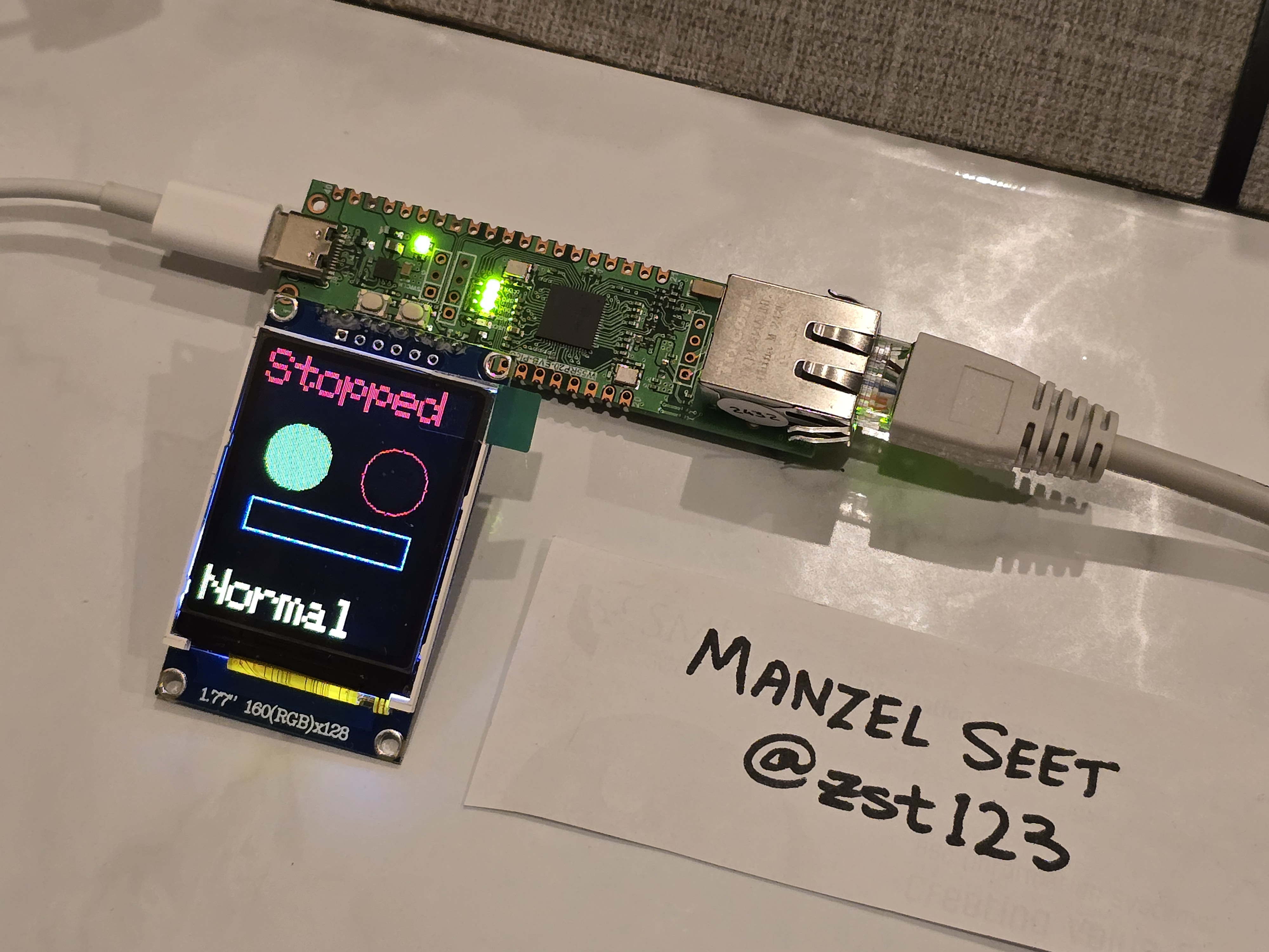
The completed code is uploaded on my Github: https://github.com/zst123/wiznet_ionic_hmi
This is a demo of how it looks like.
-
zst123
