
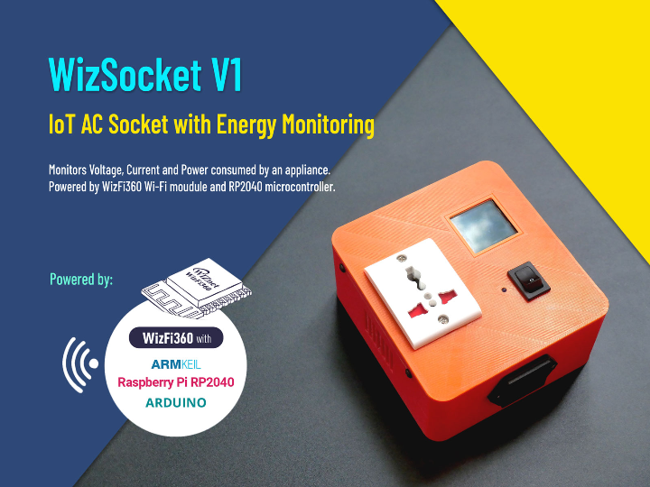
WizSocket - Cloud-Connected IoT AC Socket
A smart AC socket that can measure AC RMS voltage, current & power used by an AC appliance and send the data to the cloud via Wi-Fi.
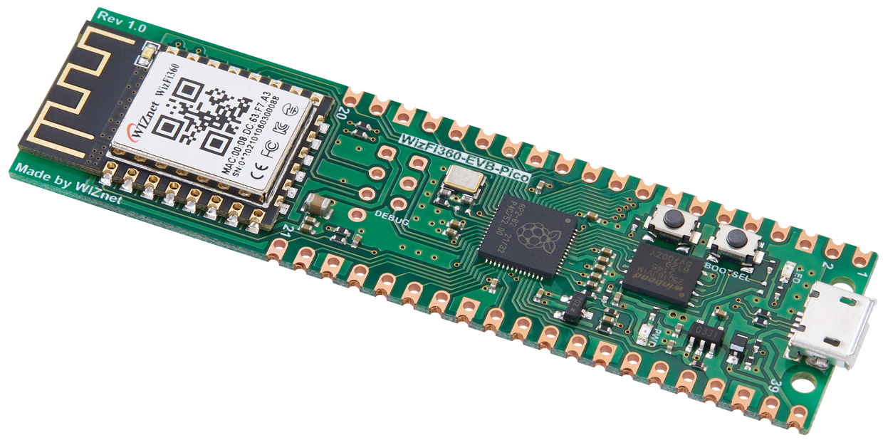
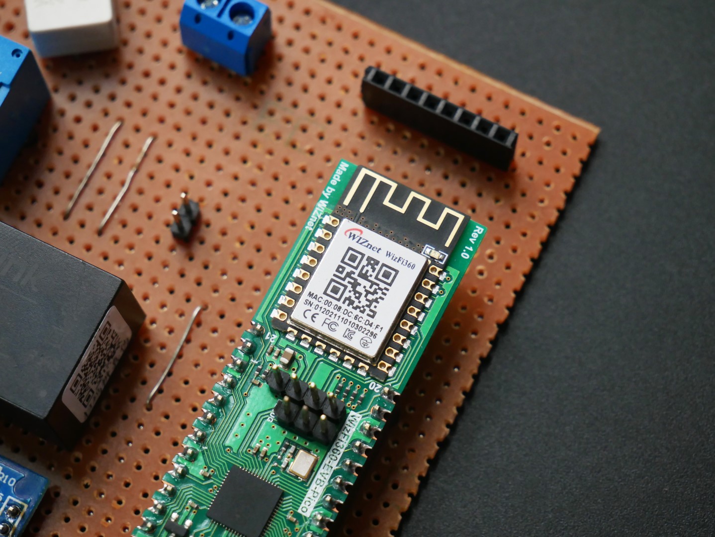
WIZnet - WizFi360-EVB-Pico
x 1

Arduino - Arduino IDE
x 1
For writing the firmware.
Kaa - Kaa IoT
x 1
IoT Platform
Introduction
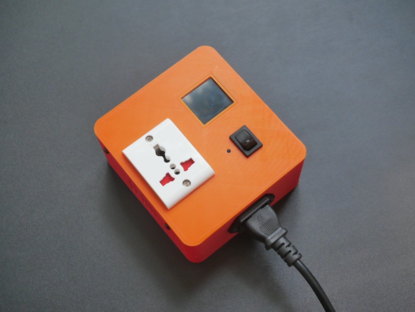
WizSocket is a cloud-connected smart IoT AC socket that can measure AC RMS voltage, current, and power used by an AC appliance and send the data to the cloud in real-time via Wi-Fi. WizSocket has a WizFi360-EVB-Pico at its heart. The onboard WizFi360 module from WizNet facilitates Wi-Fi connectivity while the RP2040 microcontroller takes care of everything else. The device has isolated current and voltage sensors for securely measuring AC voltage and current. The AC load connected to the universal socket can be turned ON or OFF with a SPDT switch. The switch tells the device to turn ON or OFF the load through a relay.
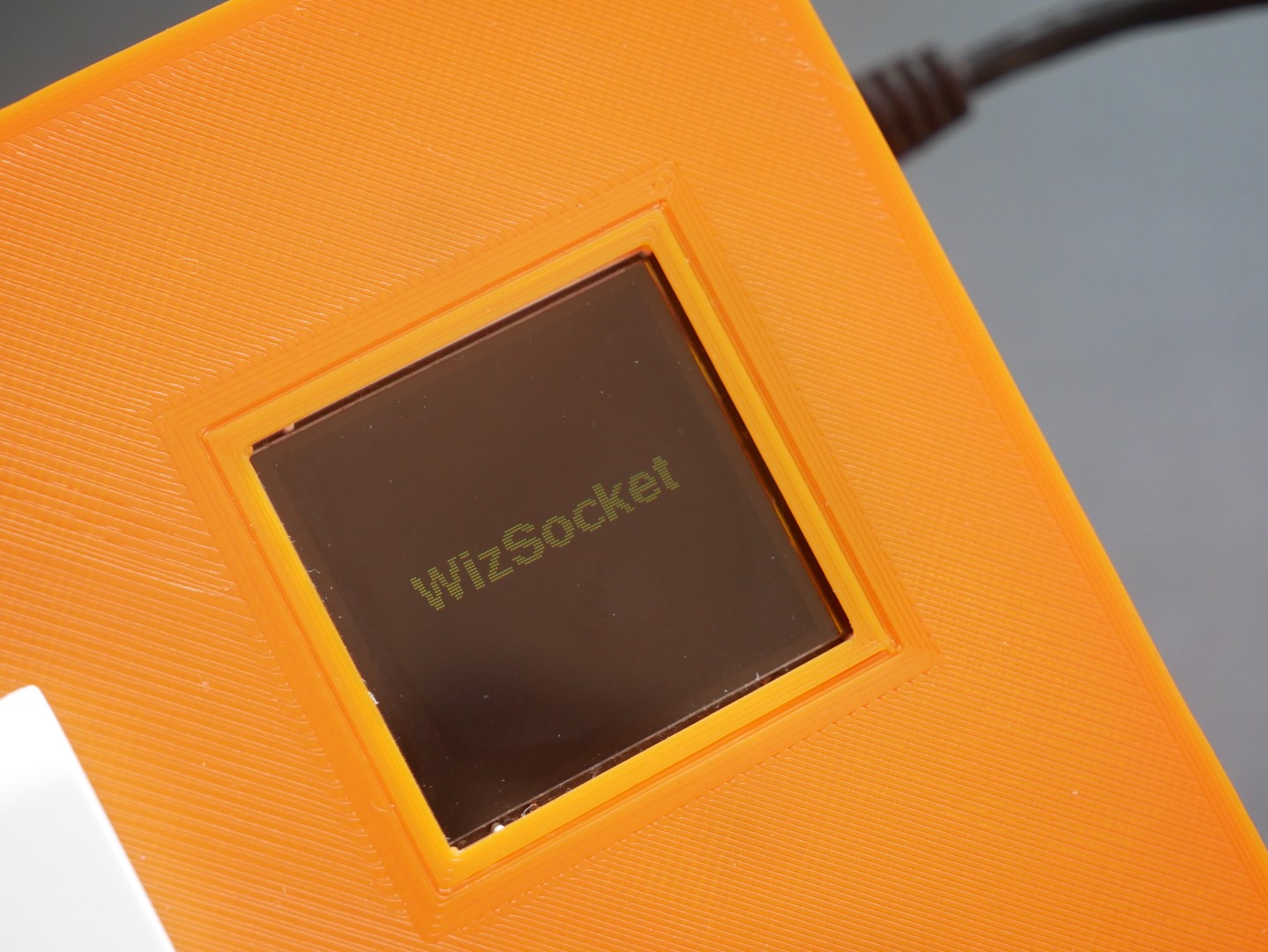
The measurements are sent to an IoT application hosted on the Kaa IoT platform. The user can monitor the parameters and device status from the dashboard. The measurements are also displayed on a 1.44" TFT LCD display so that the user can view the measurements even if the IoT dashboard is accessible.
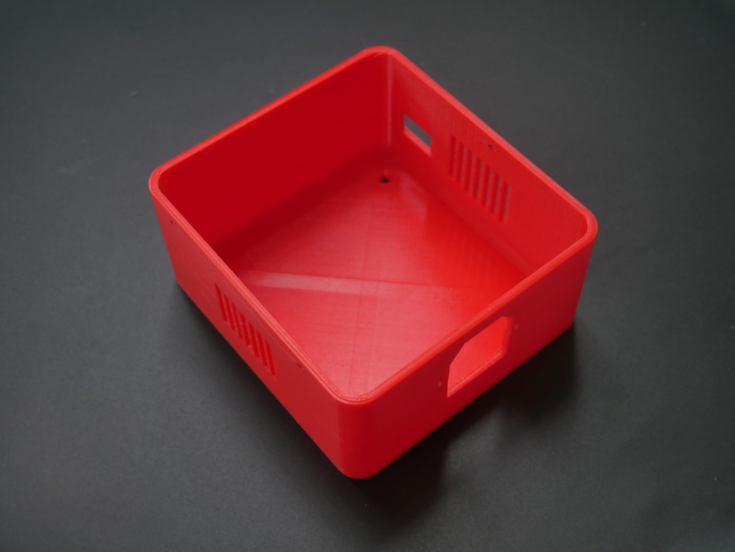
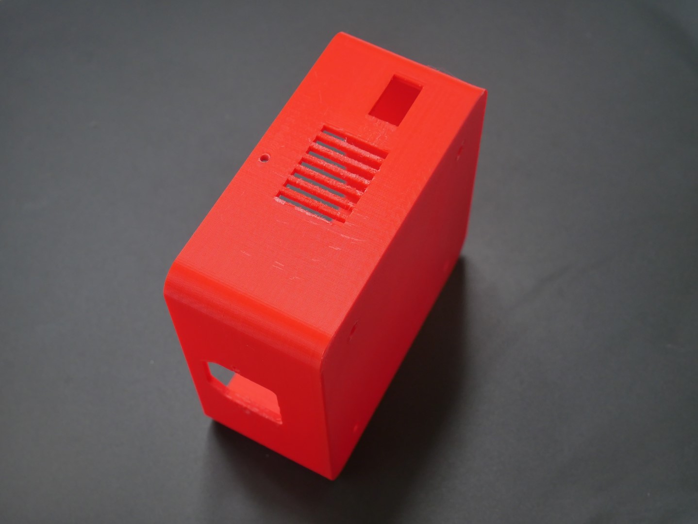
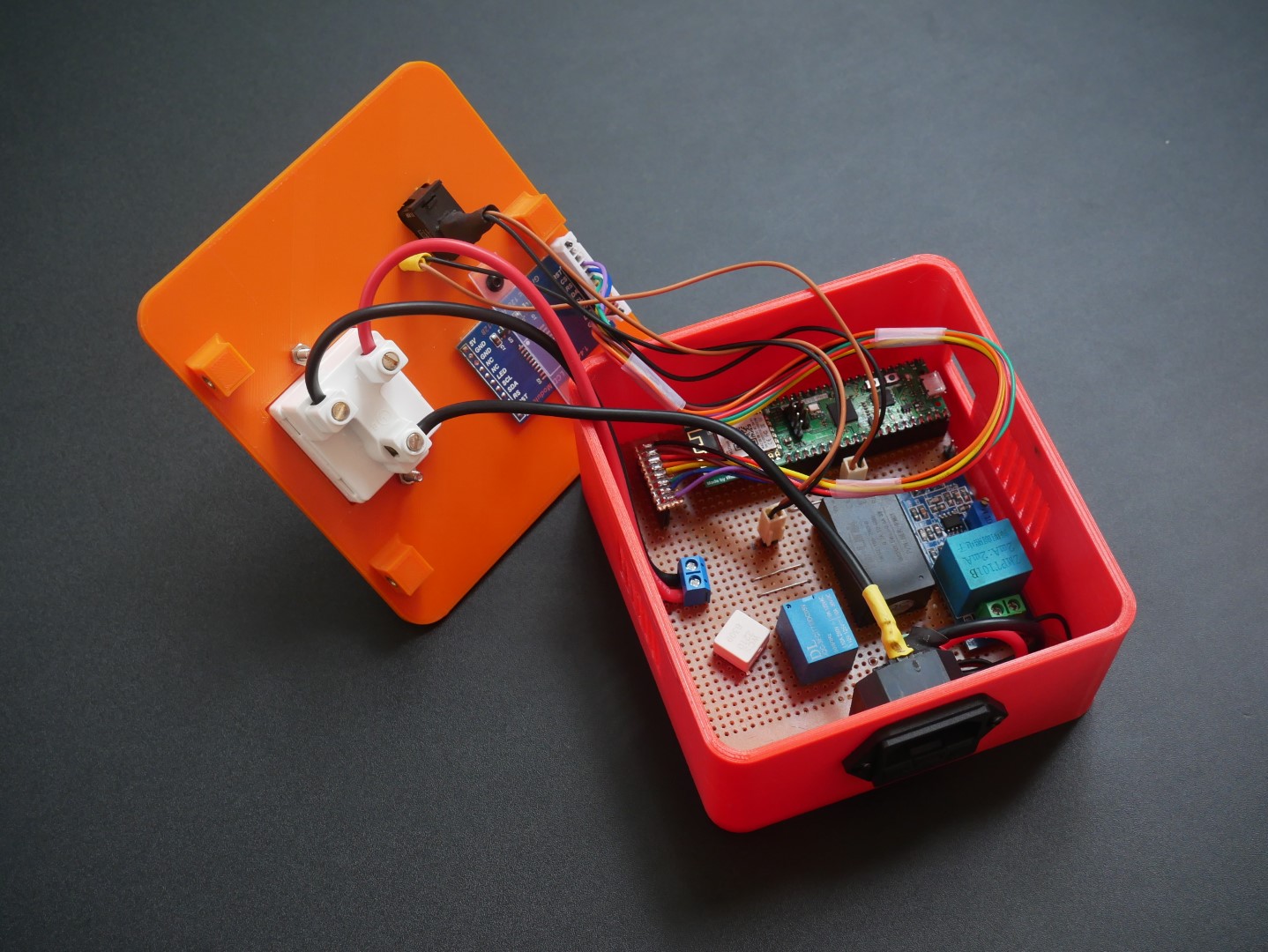
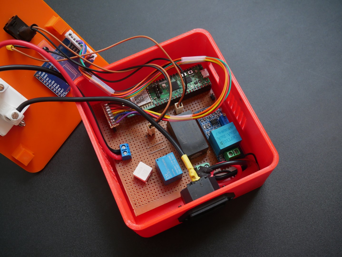
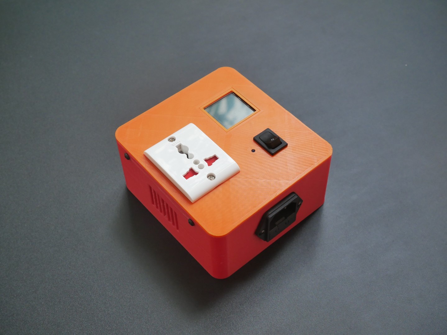
The device safely encloses everything inside a 2-piece 3D-printed enclosure. Every interface uses connectors for easy assembly and disassembly. This is the first prototype version of WizSocket and all the design files are released under MIT open-source license. We will improve the device design with the upcoming versions, adding more features and optimizations.
Features
- Powered by Wiznet WizFi360 Wi-Fi module and Raspberry Pi RP2040 microcontroller.
- Real-time AC RMS voltage, current, and power measurements.
- Kaa IoT cloud communication with MQTT.
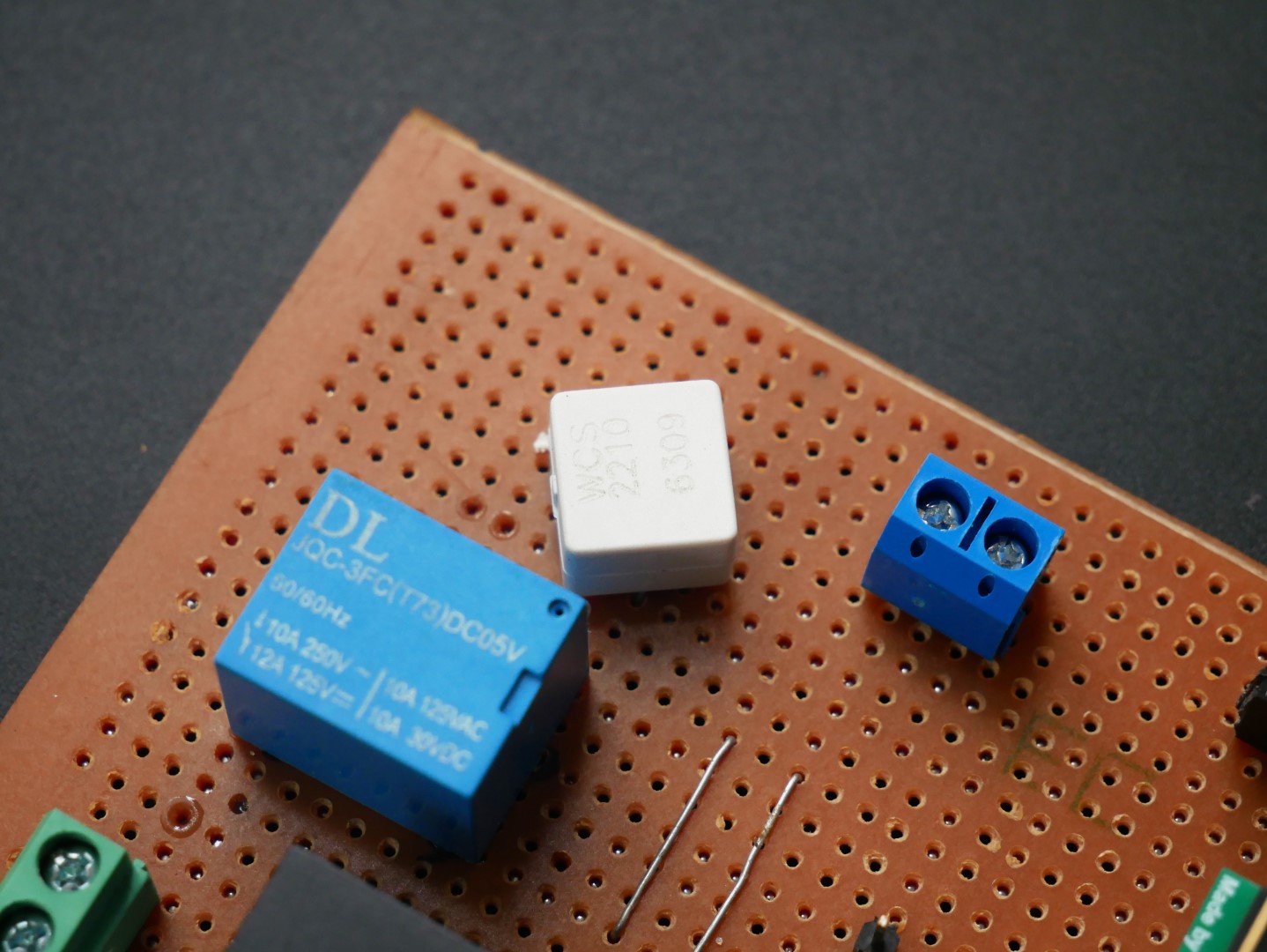
- WCS2210 15A Hall-based current sensor.
- ZMPT101B isolated AC voltage sensor.
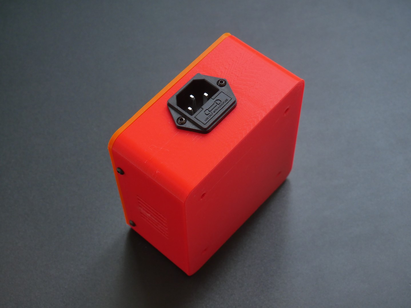
- IEC C-14 AC socket for input.
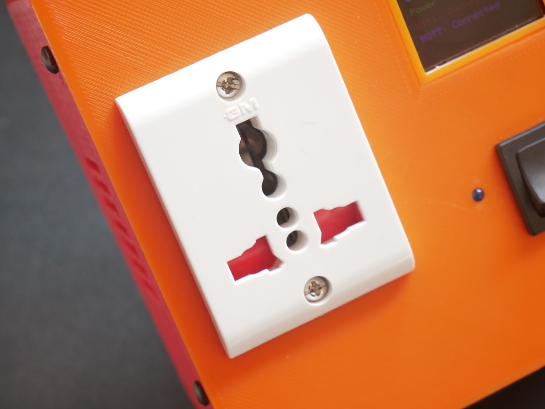
- Universal AC socket for output.
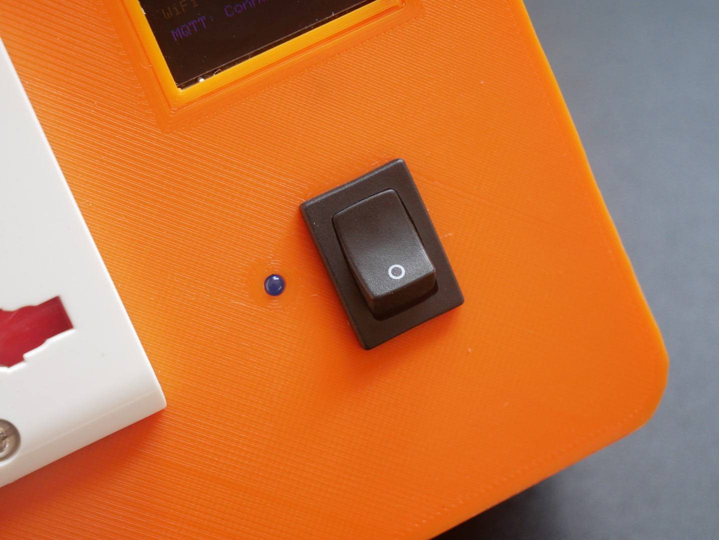
- Rocker switch to turn ON/OFF the load.
- LED indicator for load status.
- 1.44" TFT LCD.
- 3D-printed enclosure.
Things Required
Hardware
- 1 x WizFi360-EVB-Pico Development Board
- 1 x Winson WCS2210 Current Sensor
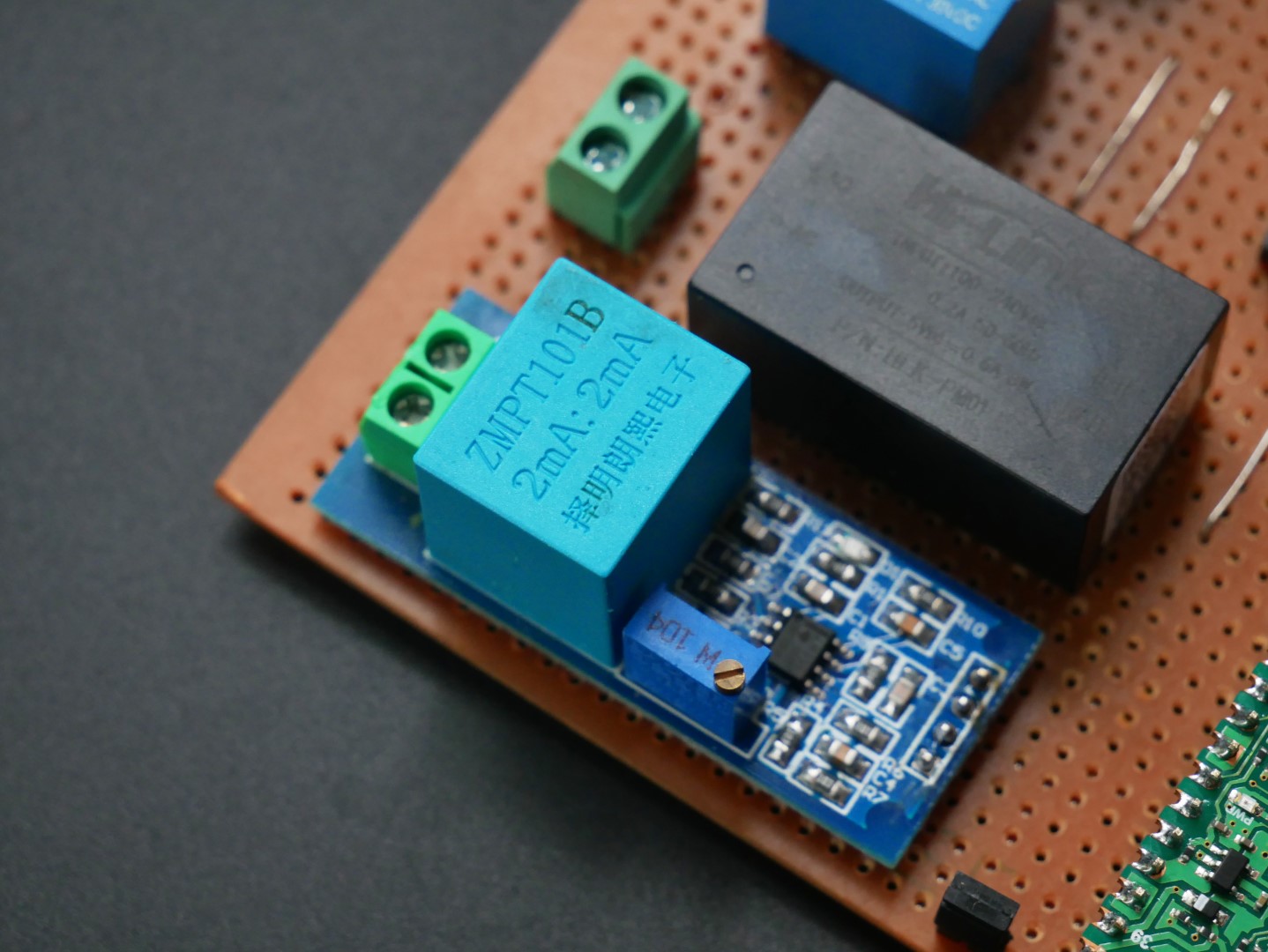
- 1 x Hi-Link HLK-PM01 AC-DC Module
- 1 x ZMPT101B Voltage Sensor Module
- 1 x 250V/10A, 5V DPDT Sugarcube Relay
- 1 x IEC C-14 AC Socket with Fuse
- 1 x 1.44", 128 x 128 TFT LCD with ST7735
- 1 x GM Universal AC Socket
- 1 x SPDT Rocker Switch 6A
- 3 x M3 6mm Threaded Inserts
- 3 x M3 8mm Hex Buttonhead Screws
- 2 x M3 3mm Threaded Inserts
- 2 x M3 5mm Hex Buttonhead Screws
- 2 x M3 10mm Hex Buttonhead Screws
- 1 x Set of 3D Printed Enclosure
- 2 x Screw Terminals
- 2 x 3mm Blue LED
- 1 x 8-pin JST-XH Connector Cable
- 2 x 2-pin RMC Connector Cable
- 1 x 6" x 4" Perfboard
Software
- Arduino IDE
- Kaa IoT Platform
- KiCad
- Fusion 360
Tools
- Soldering Iron
- Digital Multimeter
- 3D Printer (or Service)
- Assortment of Hant Tools
Device Operation
WizSocket has an IEC C-14 input socket for AC power input. It can accept AC voltages in the range of 90 ~ 264V (50/60Hz). The internal AC-DC converter module will convert this voltage to 5V and 3.3V supplies required for all the internal peripherals. Additionally, the device can be powered by connecting the Micro-USB. But this must be limited to testing only. There is no ON/OFF switch for the device. This means, WizSocket will be always powered when either the AC input or USB input is active.
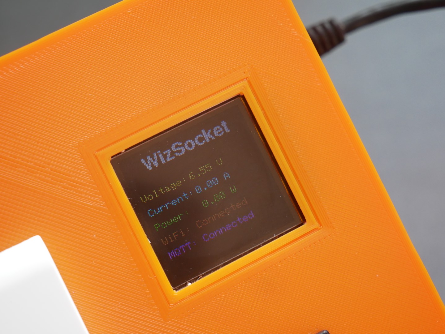
When power is applied, the splash screen will show “WizSocket” for a few seconds. The device will try to connect to the Wi-Fi network and establish an MQTT connection to the IoT server. Once connected, the device will start measuring the AC supply parameters and send the data to the cloud at regular intervals. WizSocket will also send the load status to the server, telling whether the load is ON or OFF. The data sent by WizSocket can be monitored at the Kaa IoT dashboard specifically created to show voltage, current, power, and load status.
You can turn on the load by flipping the rocker switch to ON position. This will tell the device to activate the relay and supply power to the connected load. The blue LED will also turn on to indicate the load is active. Every time you flip the rocker switch, the load status will change and the updated status will be sent to the cloud. Shown below is the IoT dashboard for WizSocket.

A few of the Kaa IoT widgets are utilized to create the dashboard. The Load Status indicates whether the load is ON or OFF. This status changes when you flip the rocker switch. You can also turn ON/OFF the load by toggling this widget (due to some bugs, this function doesn’t work for now). The Voltage RMS shows the AC voltage, Current RMS shows the AC current supplied to the load and the Power RMS shows the power consumed by the load. The parameters are also logged to the server and you see the historic values by changing the time span in the graph.
Safety Precautions
Since this project deals with high AC voltages, you need to be extremely careful when building this project. Please follow the precautions listed below to prevent harm to yourself, others, and your properties.
- Always disconnect the AC input and load from the device before trying to do anything.
- Wait for any capacitors to discharge before touching any metal contacts, such as when you need to solder something, or use a screwdriver.
- Do not operate the device without the enclosures.
- Do not leave anything connected and unattended.
- Use insulation tape or heat-shrink tubes properly to insulate terminals and joints.
- Wear shoes and insulating gloves when working with applications involving AC voltages.
- Always use fusing, earthing, and short-circuit protection in the working environment.
Working Explained
Block Diagram

Shown above is the block diagram for WizSocket. The Neutral and Earth lines from the input socket are directly connected to the output socket. We only need to control the Line supply which is accomplished with a relay. The hall current sensor is placed in series with Line supply after the relay. The output from the current sensor will be an analog voltage in the range of 0-5V, proportional to the current measured. The value will remain at 2.5V when there is no current. The analog output is connected to one of the ADC input pins of WizFi360-EVB-Pico board. The instantaneous output voltage will be converted to an RMS current value by taking multiple samples.
The voltage sensor also produces an output voltage in the range 0-5V proportional to the AC voltage. This output is also connected to an ADC pin of the microcontroller. The instantaneous voltages will be converted to an RMS value before sending to the cloud. WizFi360-EVB-Pico will also send the values to the TFT display via SPI and send the data to the cloud via Wi-Fi.
WizFi360-EVB-Pico

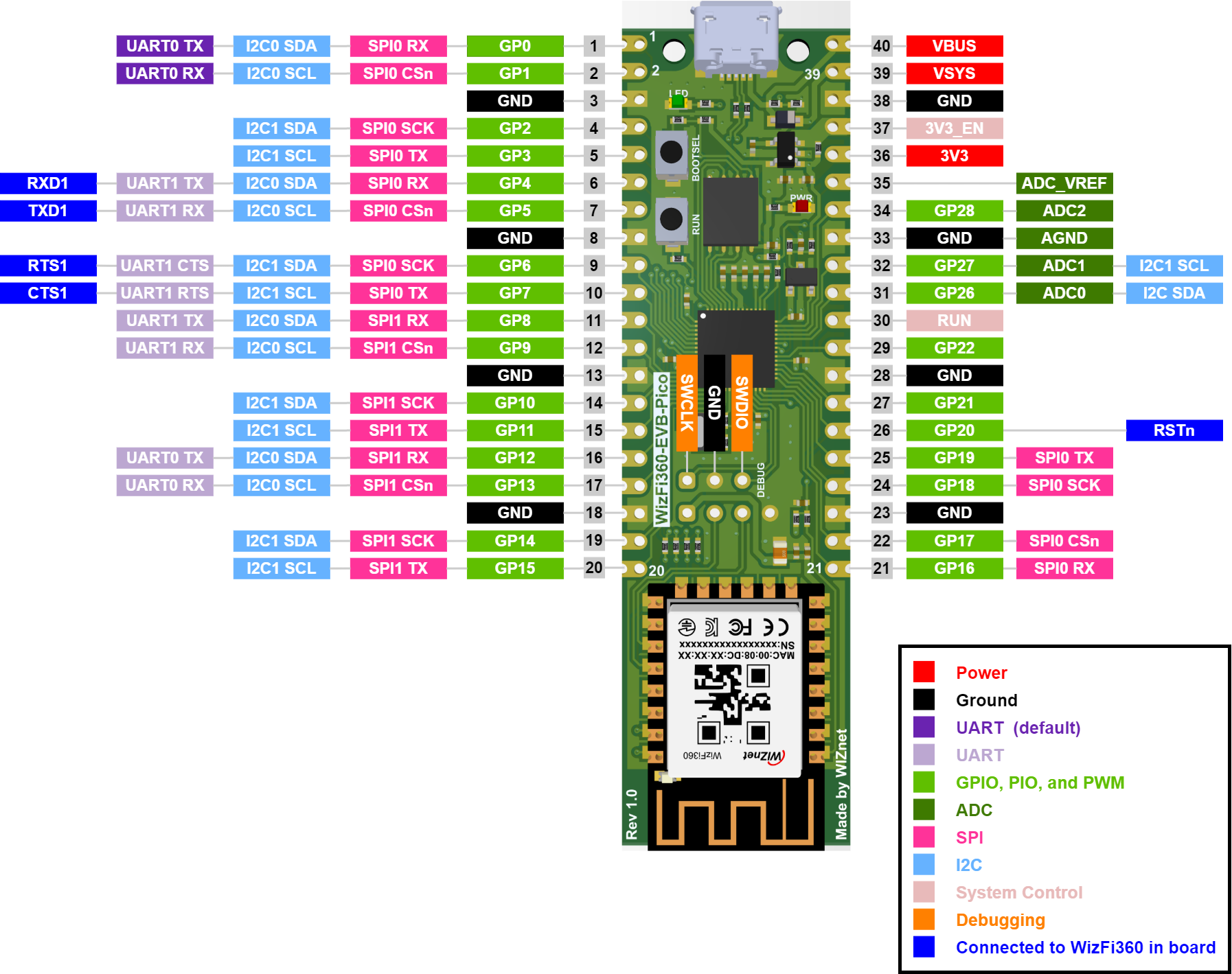
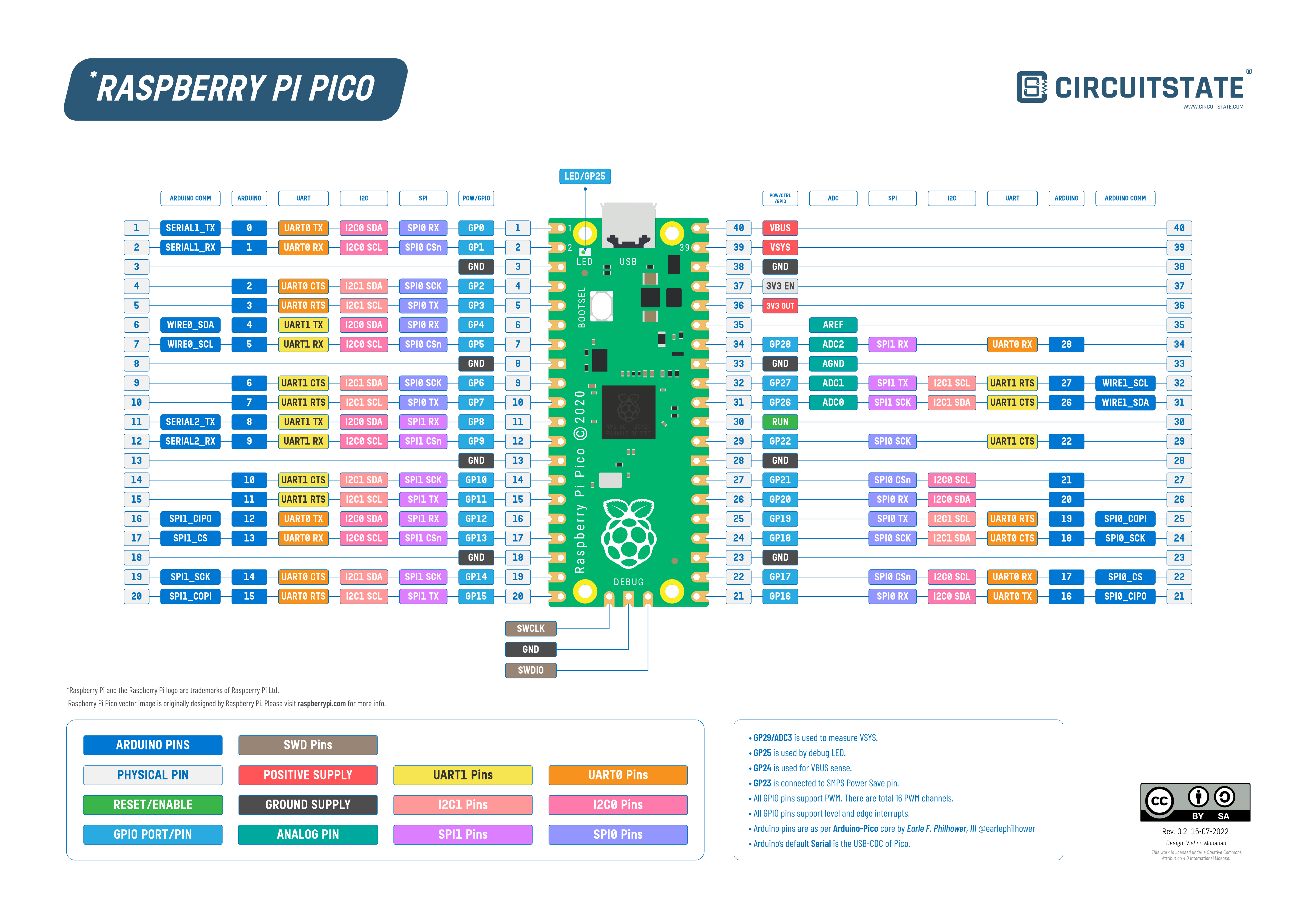
WizFi360-EVB-Pico is an RP2040 development board from WizNet which also combines their WizFi360-PA precertified Wi-Fi module. The WizFi360-EVB-Pico is designed after the same form factor and pinout as the official Raspberry Pi Pico. So the board is pin and function compatible with the Pico.
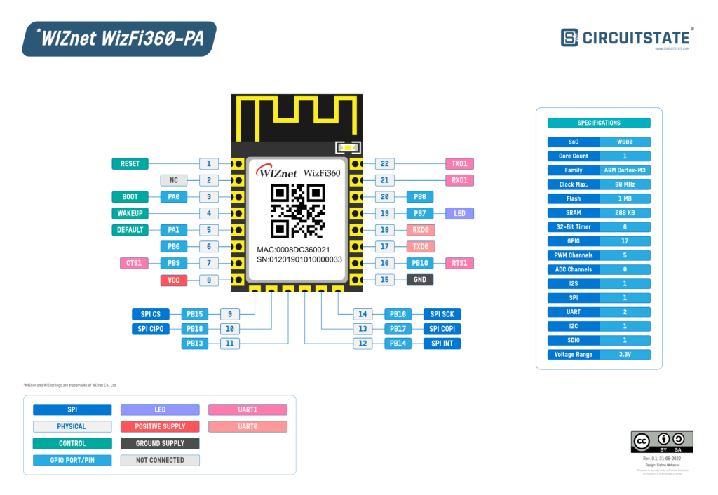
WizFi360-PA
WizFi360-PA is a precertified Wi-Fi module based on the W600 wireless SoC. W600 is a single-core ARM Cortex M3 microcontroller that integrates a Wi-Fi radio and other peripherals. The CPU can run at a maximum clock of 80MHz. It has an SRAM of 288 KB and a flash memory of 1 MB. The chip has a rich set of peripherals and cryptographic accelerators. The nominal working voltage is 3.3V and the QFN-32 measures just 5 x 5mm.


WizFi360-PA comes with a PCB trace antenna and the module is certified by CE, FCC, KC, K-MIC(TELEC), RoHS, and REACH. WizFi360-PA has a sibling named WizFi360-CON that has a U.FL connector instead of a PCB antenna.
RP2040

RP2040 is an ARM Cortex-M0+ microcontroller. It is a dual-core microcontroller. That means you have two separate processors inside the package that can execute your code parallelly. It’s like having two microcontrollers for the price of one. Both cores run at 133 MHz and they could be even overclocked! Cortex-M0+ is a series of ARM microcontrollers that are optimized for power consumption. Like all ARM Cortex microcontrollers, RP2040 also has a 32-bit core, which means it can execute complex 32-bit instructions at a time. It is also a RISC processor which can execute a single instruction in just 1 clock cycle.
You can learn more about the WizFi360-EVB-Pico board from this post from CIRCUITSTATE. To learn about RP2040, this post is a good one.
Winson WCS2210 Current Sensor
WCS2210 is a hall-effect-based linear current sensor from Winson. It can measure up to 12A AC or DC current and the operating voltage is 3V to 12V. The output of the sensor is a DC voltage proportional to the measured current. We use any ADC to measure the output voltage and calculate the current figure.

ZMPT101B Voltage Sensor Module

This voltage sensor module uses ZMPT101B voltage transformer with an output proportional to the input current. The input and output currents follow a 1:1 ratio. The output current is converted to a voltage in the range of 0-5V by an op-amp IC. The output can be directly read with an ADC and the AC voltage can be calculated. Since the output will follow the input, we need to convert the instantaneous values to an RMS figure in order to show it on a display.
TFT LCD
The TFT LCD used in WizSocket is a 1.44″ LCD from IC Station with a resolution of 128 x 128 pixels. It has an SPI interface and supports both 3.3V and 5V supplies. We are using the 3.3V SPI interface.

Power Supply
The power supply we are using is the HLK-PM01 from Hi-Link. This is an AC-to-DC converter with 5V output at a maximum current of 0.6A (total 3 Watts).

Kaa IoT Platform
Kaa IoT is an enterprise-grade IoT platform. It has a rich set of features and modern IoT dashboard interfaces. With a free account, you can connect up to 5 devices. We will be using the free service to connect WizSocket to the IoT dashboard and log and visualize data there.

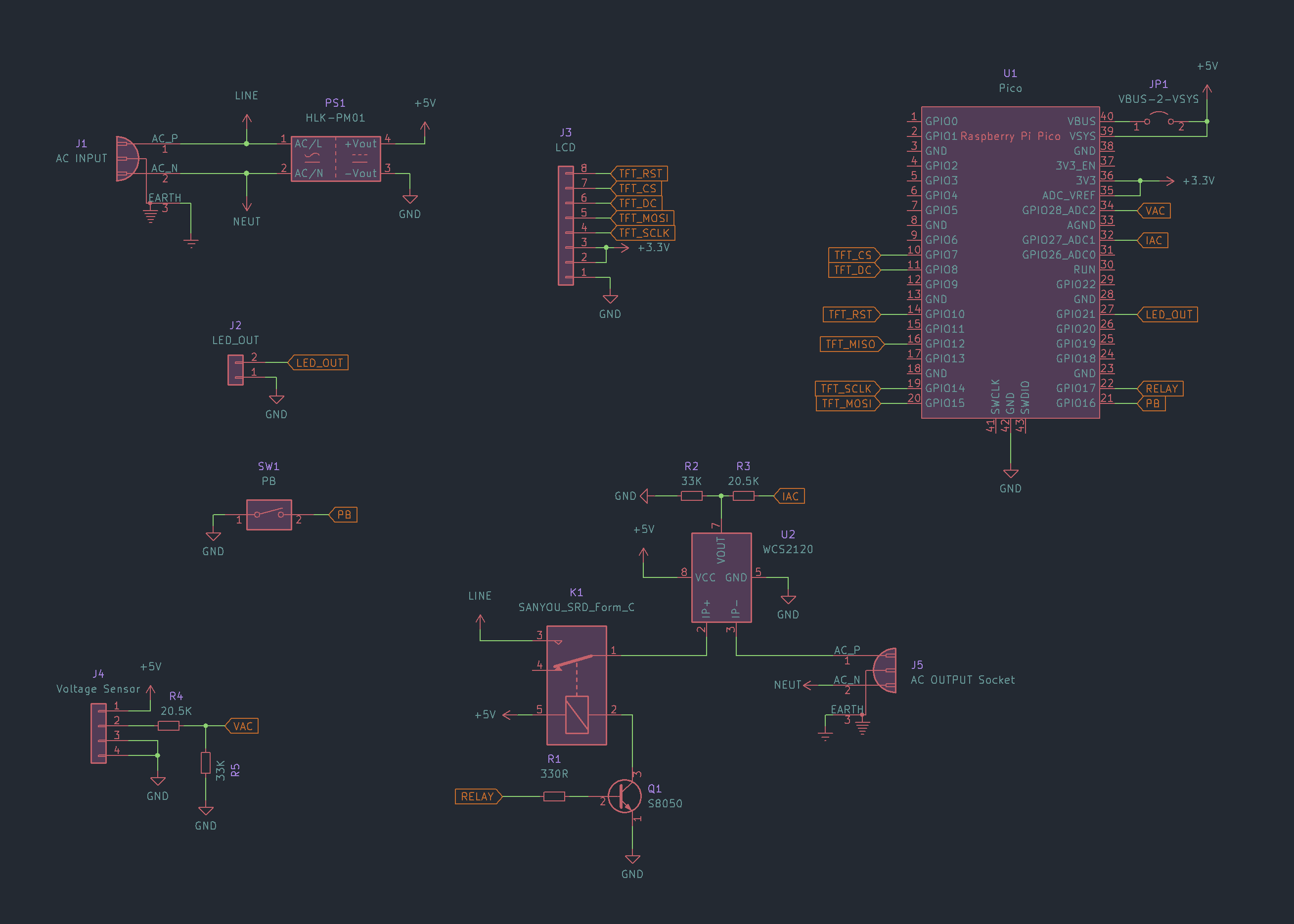
Schematic
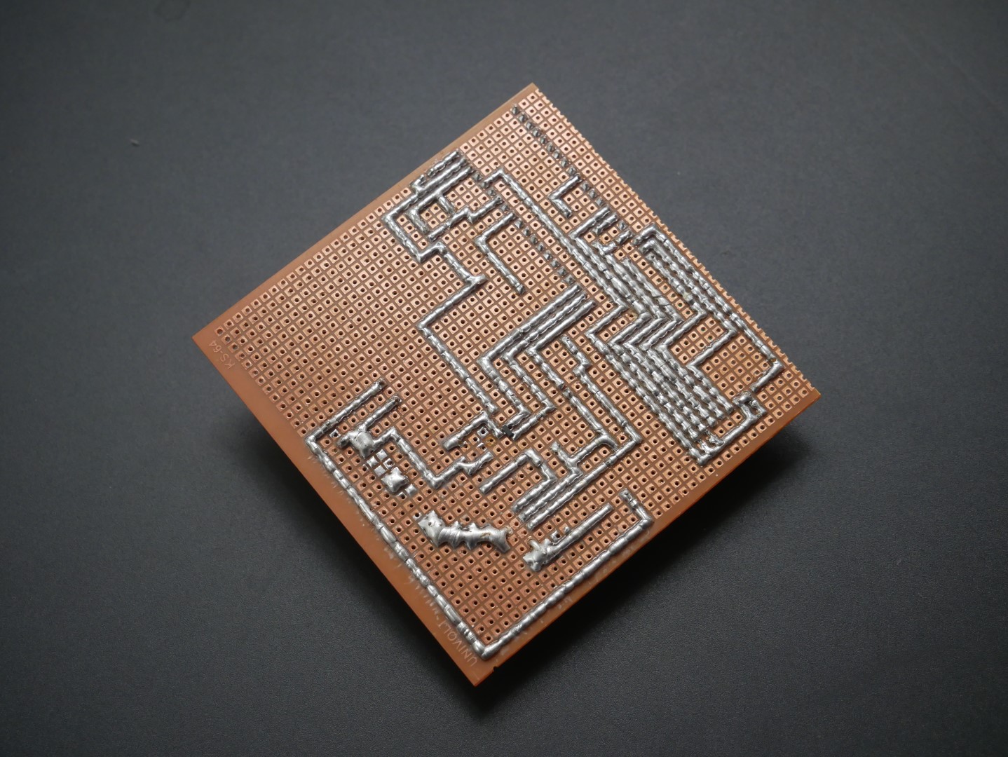
Since this is the V1 prototype of WizScoket, we are not designing a dedicated PCB for it. Instead, we will use a perfboard for soldering all the components. Still, we need a schematic for wiring everything. The following schematic can be used as a reference for modifying the design. The schematic was designed in KiCad v6. You can download the KiCad source file from the downloads section below.
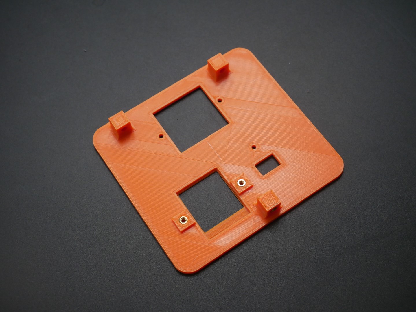
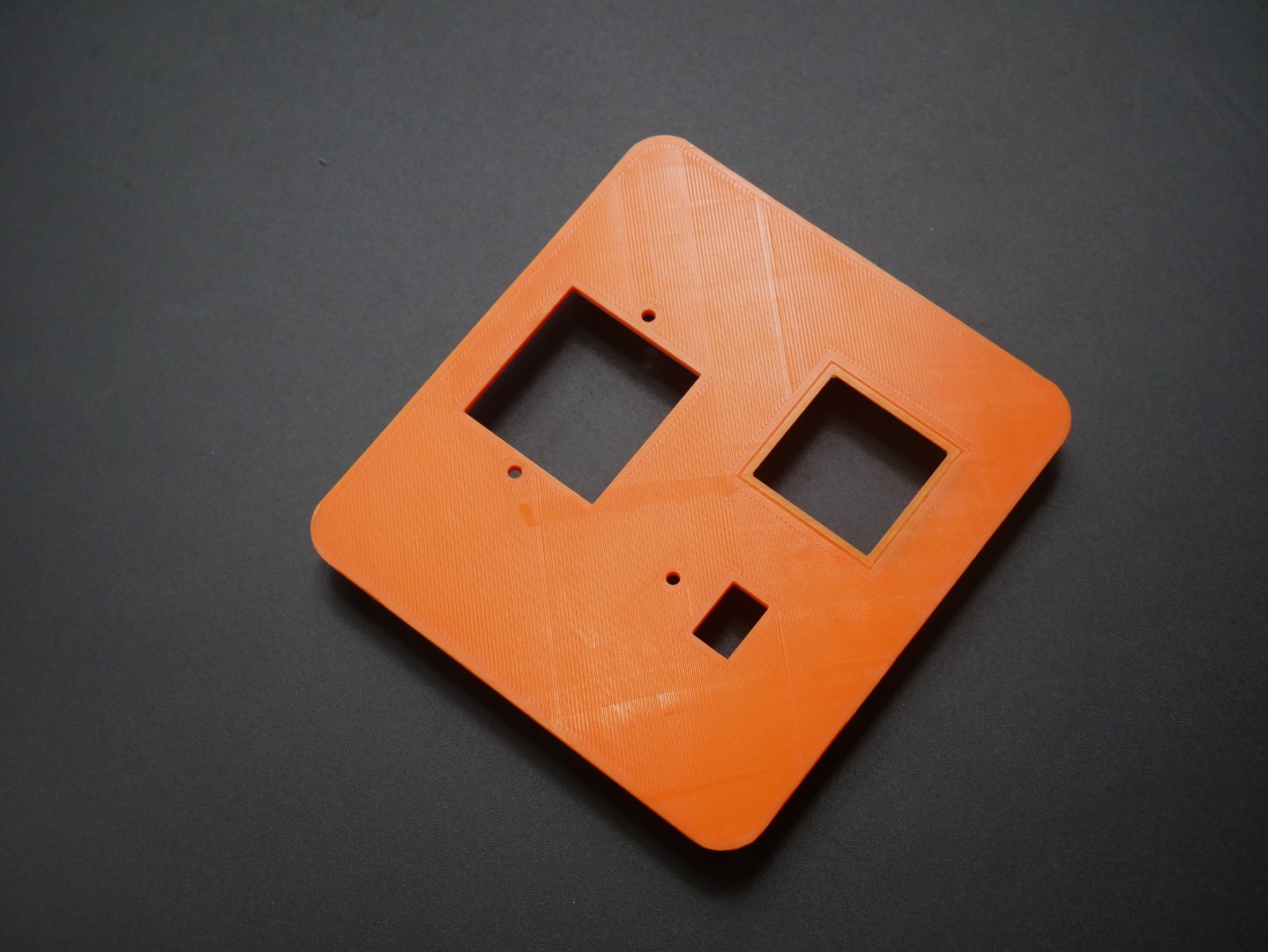
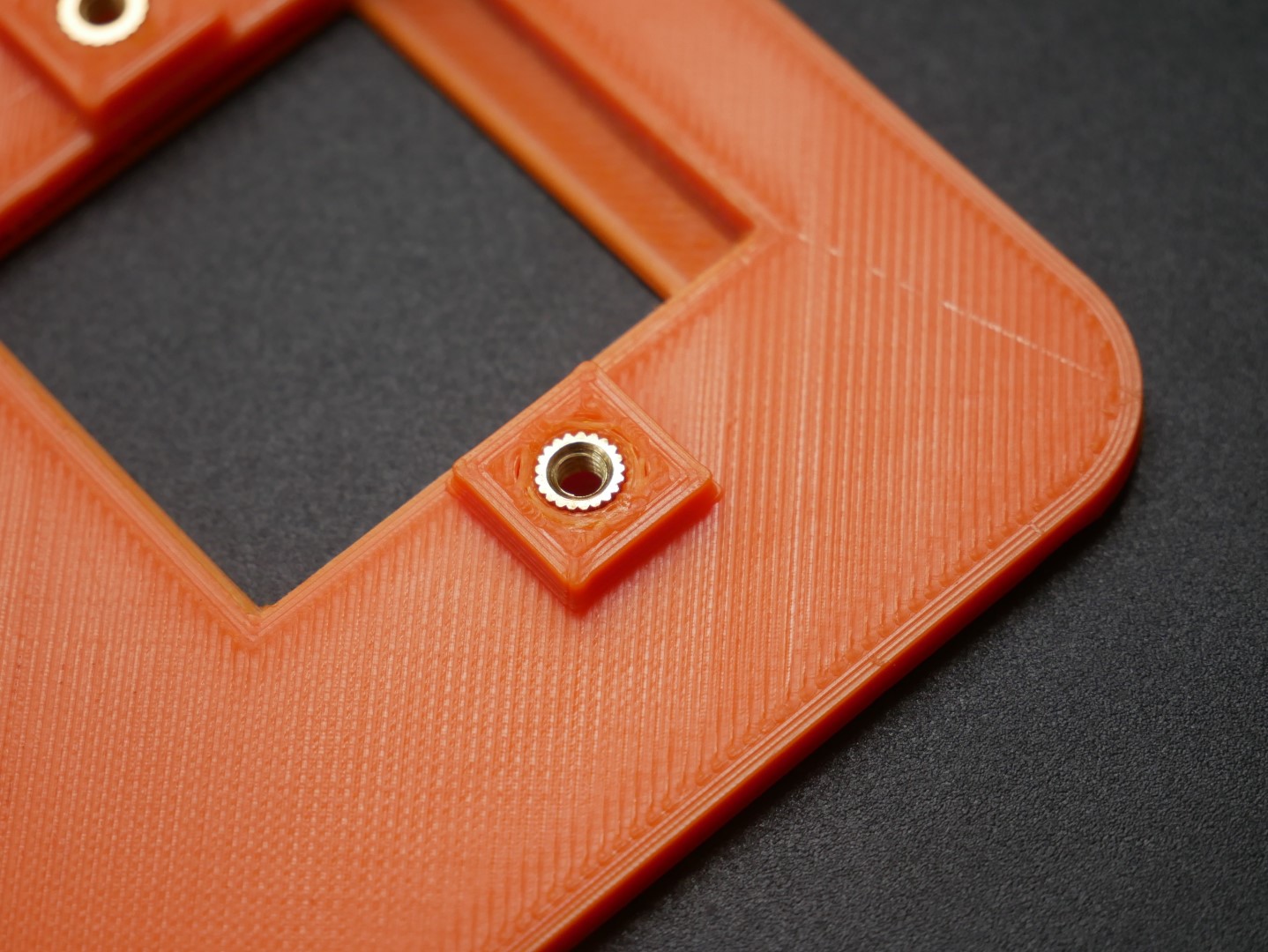
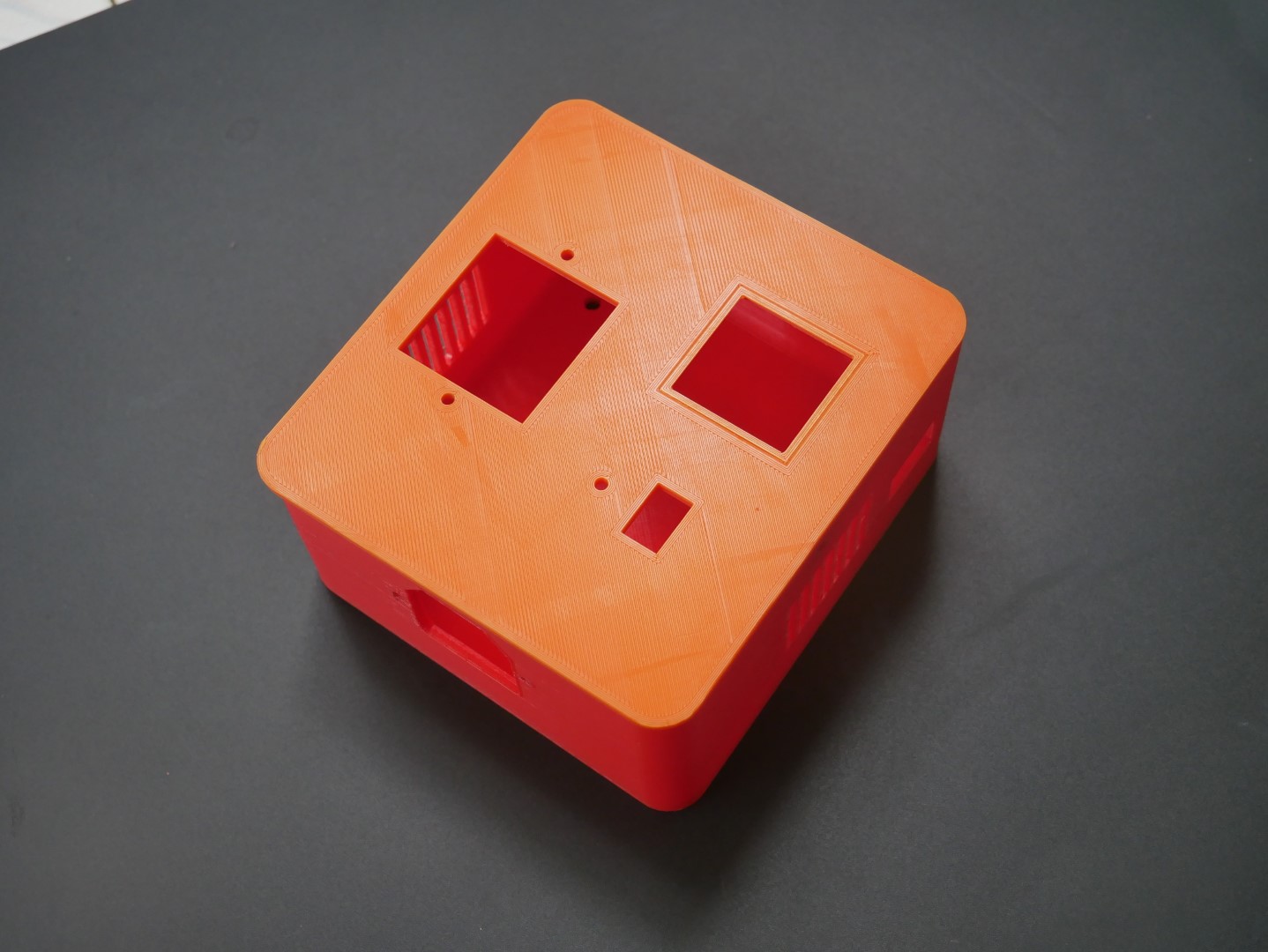
3D Enclosure Design
The 3D enclosure was designed Fusion 360 and you can download the model as F3D file. The enclosure is a 2-part design and you can use a few threaded inserts and M3 screws to fasten them together.
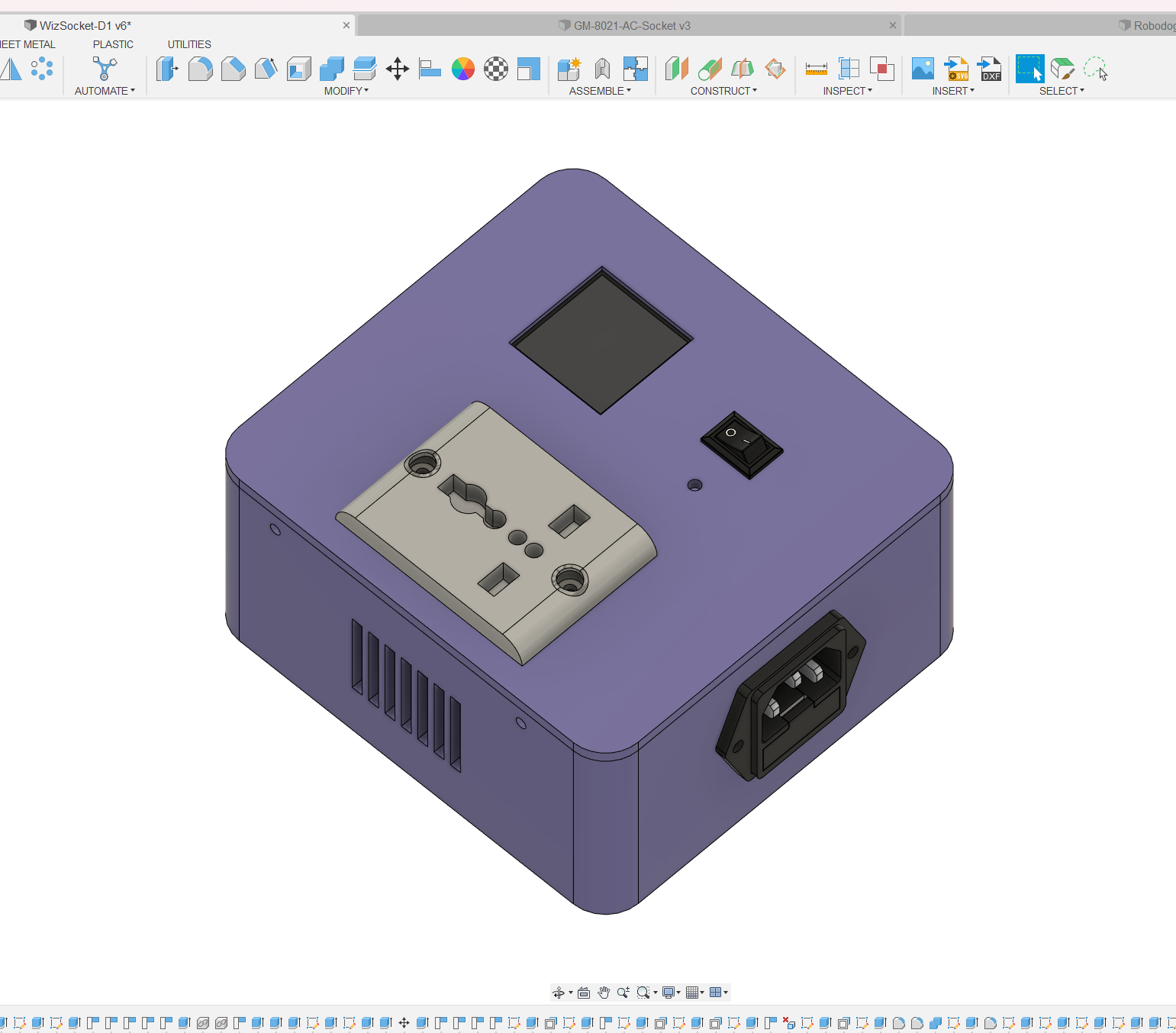
Since I did not include the actual PCB in the design, I couldn’t be sure about the size or placement of the cutout for the Micro-USB. So the cutout is unusually large and is not aligned either. I suggest you modify the design according to your PCB design.
Firmware
The firmware is written in the Arduino platform making use of multiple open-source libraries. Following is a list of libraries we have used.
- WizFi360.h – this library helps us to communicate with the WizFi360 module and utilize Wi-Fi functions in the project.
- PubSubClient.h – this is a generic library that allows us to send and receive MQTT messages on any Arduino-supported boards as long as it has a Wi-Fi module connected. The library is developed by Nick O’Leary.
- ArduinoJson.h – this library helps us to generate and extract JSON string objects in the Arduino environment. Most of the data we are sending and receiving is in the form of JSON objects. This library is developed by Benoit Blanchon.
- ptScheduler.h – this is a generic timing library that can be used to run periodic tasks without blocking the rest of your code. We use ptScheduler tasks for all periodic tasks such as refreshing the LCD. This library is developed by Vishnu Mohanan.
- kaa.h – this is an official Arduino library from Kaa to use their platform with various Arduino-supported boards. We use this library to send and receive messages from the Kaa IoT dashboard.
- TFT_eSPI.h – this is a versatile LCD driver and TFT graphics library that supports a wide variety of LCD modules out there. The library supports most Arduino-supported boards. We are using this to drive out 1.44″ LCD with ST7735 controller.
The complete source code of WizSocket can be found on GitHub here. You are free to fork, modify and redistribute it under MIT open-source license. Now let’s understand how the code works. I will describe each function separately.
Macros
//Baudrate
#define SERIAL_BAUDRATE   115200  //USB
#define SERIAL2_BAUDRATE  115200  //Wi-Fi module

#define KAA_HOST "mqtt.cloud.kaaiot.com"
#define KAA_PORT 1883
#define KAA_TOKEN "<token value>"      // Endpoint token - you get (or specify) it during device provisioning
#define KAA_APP_VERSION "<app version name>"  // Application version - you specify it during device provisioning

#define PIN_VAC     28  //GP28, D28, ADC2, AC voltage output
#define PIN_IAC     27  //GP27, D27, ADC1, AC current output
#define PIN_RELAY   17  //GP17, D17, Output relay
#define PIN_PB      16  //GP16, D16, Push button
#define PIN_LED_DBG    25  //GP25, D25
#define PIN_LED_OUT    21  //GP25, D25

// //LCD pins for reference. These must be defined in the TFTeSPI User Setup file.
// //Pico SPI1
// #define TFT_CS     7   // Chip select control pin
// #define TFT_DC     11  // Data Command control pin (RS pin)
// #define TFT_RST    10  // Reset pin (could connect to NodeMCU RST, see next line)
// #define TFT_MOSI   15
// #define TFT_MISO   12
// #define TFT_SCLK   14
These are global macro values that you need to change according to your application. It is a good idea to leave the serial port baud rates. The Kaa IoT platform-specific values can be changed in the subsequent lines. You need to replace the <toke value> with the correct token value of your Kaa IoT device which can be obtained during the provisioning stage. The <app version name> should be replaced with your Kaa IoT app version string. This can be found in the dashboard.
Next, you can see the pins assignments we are using. You may change the pins according to toy your application. The SPI pins for the LCD are actually defined in the tft_setup.h but added in the main sketch for reference. The TFT configuration file is shown next.
TFT Configuration
//WizPlug with 1.44", 128 x 128, ST7735 LCD

#define ST7735_DRIVER      // Define additional parameters below for this display

#define TFT_RGB_ORDER TFT_BGR  // Colour order Blue-Green-Red

#define TFT_WIDTH  128
#define TFT_HEIGHT 128

#define ST7735_GREENTAB3

#define TFT_CS     7   // Chip select control pin
#define TFT_DC     11  // Data Command control pin (RS pin)
#define TFT_RST    10  // Reset pin (could connect to NodeMCU RST, see next line)
#define TFT_MOSI   15
#define TFT_MISO   12
#define TFT_SCLK   14

#define LOAD_GLCD   // Font 1. Original Adafruit 8 pixel font needs ~1820 bytes in FLASH
#define LOAD_FONT2  // Font 2. Small 16 pixel high font, needs ~3534 bytes in FLASH, 96 characters
#define LOAD_FONT4  // Font 4. Medium 26 pixel high font, needs ~5848 bytes in FLASH, 96 characters
#define LOAD_FONT6  // Font 6. Large 48 pixel font, needs ~2666 bytes in FLASH, only characters 1234567890:-.apm
#define LOAD_FONT7  // Font 7. 7 segment 48 pixel font, needs ~2438 bytes in FLASH, only characters 1234567890:-.
#define LOAD_FONT8  // Font 8. Large 75 pixel font needs ~3256 bytes in FLASH, only characters 1234567890:-.
#define LOAD_GFXFF  // FreeFonts. Include access to the 48 Adafruit_GFX free fonts FF1 to FF48 and custom fonts

#define SMOOTH_FONT

// For the RP2040 processor define the SPI port channel used (default 0 if undefined)
#define TFT_SPI_PORT 1 // Set to 0 if SPI0 pins are used, or 1 if spi1 pins used

#define SPI_FREQUENCY  27000000
#define SPI_READ_FREQUENCY  20000000
// #define SPI_TOUCH_FREQUENCY  2500000
Global Variables
const char* ssid = "<ssid>";  // WiFi name
const char* password = "<password>";  // WiFi password
const char* broker = KAA_HOST;
const String TOKEN = KAA_TOKEN; // Endpoint token - you get (or specify) it during device provisioning
const String APP_VERSION = KAA_APP_VERSION; // Application version - you specify it during device provisioning

WiFiClient wizfiClient; //web client object
PubSubClient mqtt(wizfiClient); //MQTT object
Kaa kaa (&mqtt, KAA_TOKEN, KAA_APP_VERSION);  //KAA object

ptScheduler publishTask (PT_TIME_1S * 5);  //publishes data to the server
ptScheduler mqttLoopTask (PT_TIME_1S); //processes MQTT messages and states
ptScheduler lcdTask (PT_TIME_500MS);  //refreshes the LCD contents
ptScheduler adcTask (PT_TIME_100MS);  //samples the ADCs and convert the values

bool load_state = false;  //load ON/OFF state
bool last_load_state = true;  //previous load state
int pageIndex = 0;  //current page of the LCD

float vac = 0.0;  //RMS AC voltage
float iac = 0.0;  //RMS AC current
float pac = 0.0;  //RMS AC power

//LCD
TFT_eSPI LCD = TFT_eSPI();  // Invoke custom library
You need to replace the ssid and password values with your Wi-Fi network values. We use four ptScheduler tasks. All of them are oneshot tasks and you can change their intervals by changing the input values. The LCD is refreshed every 0.5 seconds and the ADC is sampled every 0.1 seconds as you can see.
The load_state variable indicates if the output relay is ON/OFF. When you turn on the rocker switch this is status is changed automatically. The vac, iac, and pac variables contain the current voltage, current, and power.
Setup()
void setup() {
  Serial.begin(SERIAL_BAUDRATE);  //USB serial
  Serial2.begin(SERIAL2_BAUDRATE); //WizFi serial
  delay(2000);

  LCD.begin();
  LCD.setRotation(1);
  LCD.fillScreen(TFT_BLACK);
  LCD.fillScreen(TFT_BLACK);
  LCD.setTextSize(1);
  LCD.setTextColor(TFT_YELLOW);
  LCD.setCursor(20, 65);
  LCD.print("WizSocket");

  pinMode(PIN_LED_DBG, OUTPUT);
  pinMode(PIN_LED_OUT, OUTPUT);
  pinMode(PIN_IAC, INPUT);
  pinMode(PIN_VAC, INPUT);
  pinMode(PIN_RELAY, OUTPUT);
  pinMode(PIN_PB, INPUT_PULLUP);

  clearOutput(PIN_LED_DBG);
  clearOutput(PIN_LED_OUT);

  analogReadResolution(12);

  #ifdef WIZFI360_EVB_PICO
    initWizFi360();
  #endif

  //MQTT Broker setup
  mqtt.setServer(broker, KAA_PORT);
  mqtt.setBufferSize(1024);
  mqtt.setKeepAlive(3600);
  mqtt.setCallback(mqttCallback);
  kaa.setCommandCallback(&commandCallback);

  delay(2000);
}
The setup() function does all the initialization. First, it initializes the hardware serial ports. The default Serial port is the native USB port of RP2040. Serial2 is the hardware UART connected to the WizFi360-PA module. We use this port to communicate with the module via AT commands. Then we initialize the LCD and print the “WizSocket” splash screen.
Next, we can initialize all the GPIO pins we require. The PIN_PB is actually the push button or rocker switch input. We are setting it as an input with an internal pull-up resistor. Up on starting, we can keep the LED and relay outputs as LOW.
With analogReadResolution(12), we can set the ADC input resolution to 12-bit instead of the default 10-bit. This gives an ADC range of 0 to 4096.
Finally, we initialize the WizFi360-PA module by setting up the serial port. Then we can configure the MQTT broker with the address, port, callback functions, etc. The callback functions will be invoked whenever an event occurs such as when we receive an MQTT message from the server. The value of broker and KAA_PORT are defined in the initial lines of the code.
loop()
void loop() {
  setupWiFi();

  if (!getPbState()) {
    load_state = true;
  } else {
    load_state = false;
  }

  if (last_load_state != load_state) {
    if (load_state) {
      setOutput(PIN_RELAY);
      setOutput(PIN_LED_OUT);
      composeAndSendMetadata();
    } else {
      clearOutput(PIN_RELAY);
      clearOutput(PIN_LED_OUT);
      composeAndSendMetadata();
    }
    last_load_state = load_state;
  }

  if (adcTask.call()) {
    // printAdcValues();

    vac = getAcVoltage();
    // Serial.print("VAC:");
    // Serial.println(vac);

    if (load_state) {
      iac = getAcCurrent();
    } else {
      iac = 0.0;
    }
    // Serial.print("IAC:");
    // Serial.println(iac);
    pac = getAcPower();
  }

  if (!mqtt.connected()) {
    Serial.println("MQTT is not active. Trying to reconnect..");
    mqttReconnect();
  }

  if (mqttLoopTask.call()) {
    mqtt.loop();
  }

  if (publishTask.call()) {
    DynamicJsonDocument telemetry(1023);
    telemetry.createNestedObject();

    telemetry[0]["voltage"] = vac;
    telemetry[0]["current"] = iac;
    telemetry[0]["power"] = pac;

    if (load_state)
      telemetry[0]["load"] = 1;
    else {
      telemetry[0]["load"] = 0;
    }

    String topic = "kp1/" + APP_VERSION + "/dcx/" + TOKEN + "/json";
    mqtt.publish(topic.c_str(), telemetry.as<String>().c_str());
    Serial.println("Published on topic: " + topic);
  }

  if (lcdTask.call()) {
    if (pageIndex == 0) {
      LCD.setFreeFont(&FreeSansBold9pt7b);
      LCD.fillScreen(TFT_BLACK);
      LCD.setTextSize(1);
      LCD.setTextColor(TFT_WHITE);
      LCD.setCursor(20, 20);
      LCD.print("WizSocket");

      LCD.setFreeFont();
      LCD.setTextSize(1);

      LCD.setCursor(5, 40);
      LCD.setTextColor(TFT_YELLOW);
      // LCD.println("Voltage: 228 V");
      LCD.println("Voltage:");
      LCD.setCursor(55, 40);
      LCD.print(String(vac) + " V");

      LCD.setCursor(5, 55);
      LCD.setTextColor(TFT_CYAN);
      // LCD.println("Current: 4.54 A");
      LCD.println("Current:");
      LCD.setCursor(55, 55);
      LCD.print(String(iac) + " A");

      LCD.setCursor(5, 70);
      LCD.setTextColor(TFT_GREEN);
      // LCD.println("Power: 23.45 W");
      LCD.println("Power:");
      LCD.setCursor(55, 70);
      LCD.print(String(pac) + " W");

      LCD.setCursor(5, 85);
      LCD.setTextColor(TFT_GOLD);

      if (WiFi.status() != WL_CONNECTED) {
        LCD.println("WiFi: Disconnected");
      } else {
        LCD.println("WiFi: Connected");
      }

      LCD.setCursor(5, 100);
      LCD.setTextColor(TFT_MAGENTA);

      if (!mqtt.connected()) {
        LCD.println("MQTT: Disconnected");
      } else {
        LCD.println("MQTT: Connected");
      }
    }
  }
}
The loop() function is where the main tasks are running. It first calls the setupWiFi() function to connect to the Wi-Fi network if it is not already connected. The function will reconnect to the Wi-Fi if ever it is interrupted.
The getPbState() function reads the state of the push button or switch input and toggles the load_state variable accordingly. The state of load_state will be used to format the data accordingly. Whenever the load state changes we also toggle the states of the LED indicator and the relay.
Next, we invoke the adcTask.call() function to run the ADC tasks. We use the functions getAcVoltage(), getAcCurrent() and getAcPower() to get the RMS values of the current, voltage, and power.
Next, we check the MQTT connection status and reconnect if needed with the help of mqttReconnect() function. The Wi-Fi has to be already connected in order for this to work. The mqtt.loop() function will process any data on the client side.
The publishTask.call() invokes the code for publishing data to the Kaa IoT cloud. It formats the vac, iac, pac and load_status variables to a JSON object and publishes them to the MQTT server. If the sending operation is successful, you will see the data on the dashboard after a few seconds.
The lcdTask.call() simply prints all the data we have to the LCD. The loop() function then starts another iteration and continuously run the application.
The remaining functions are self-explainable as they only handle very specific tasks and I have added many comments there to help you understand them.
IoT Dashboard
Let's see how we can create a new IoT dashboard on the Kaa IoT platform. First, you need to create a free account by visiting the home page. With a free account, you can use any of the Kaa IoT features but with a limit of a maximum of 5 devices. That is usually more than enough for your IoT maker projects. There are other alternatives such as ThingSpeak, Ubidots, etc. But Kaa IoT has the best dashboard and feature set among them.
Once you have created the account, head over to your dashboard and add a new device by clicking the Add a device button.
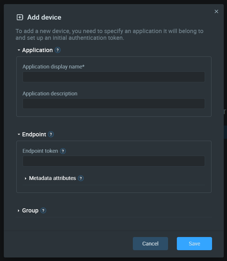
Every device has an Application associated with it. An application is simply a construct that acts as the device twin. So the application name should be your device name. You can put WizSocket there. The description can be any.
The Endpoint is a unique ID of the device that you can set manually or leave blank for generating one automatically. Kaa will use GUIDs to generate new IDs. Group is a group of similar devices based on type, location, etc. You can leave that blank for now.
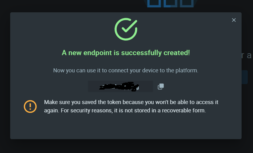
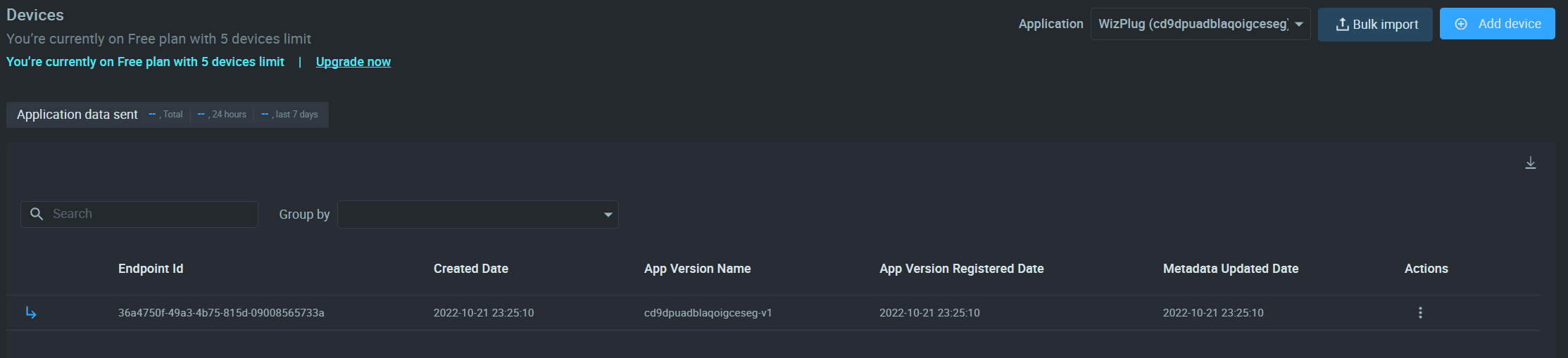
Once you have added the device, you will get the token. Save the token safely because you can get it later. Now you will be able to see the new devices under the Devices tab.
Now we need to configure the application to collect and process incoming data. Go to the Applications tab.
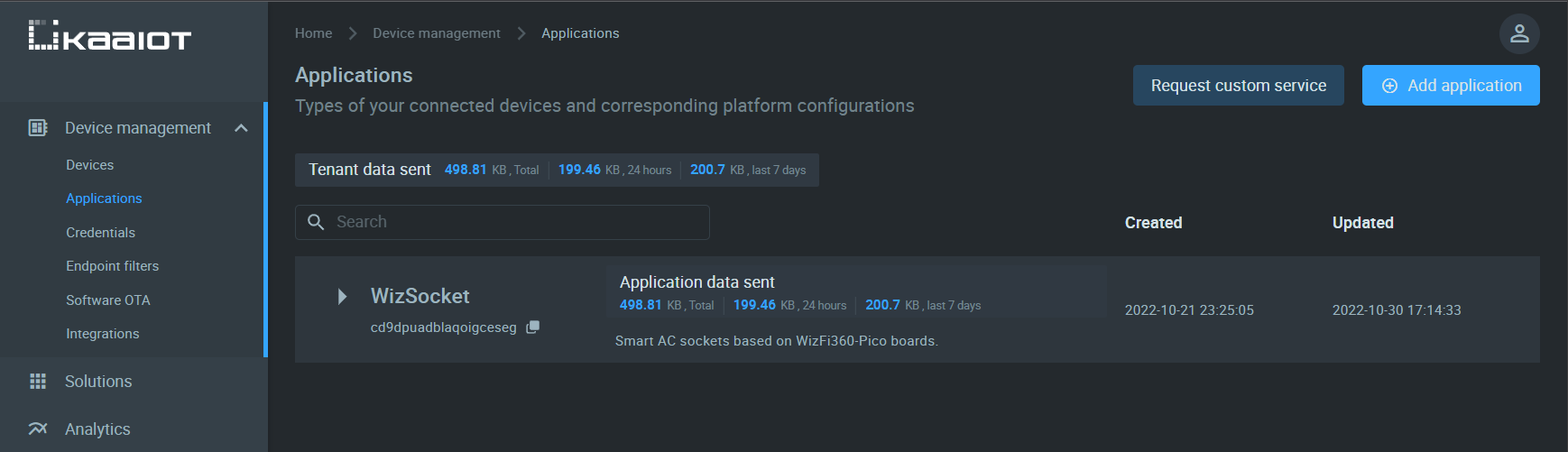
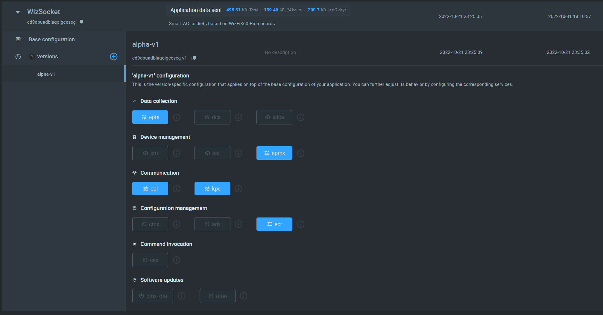
You will see the previously created application here. Click on the Base configuration by expanding the selection.
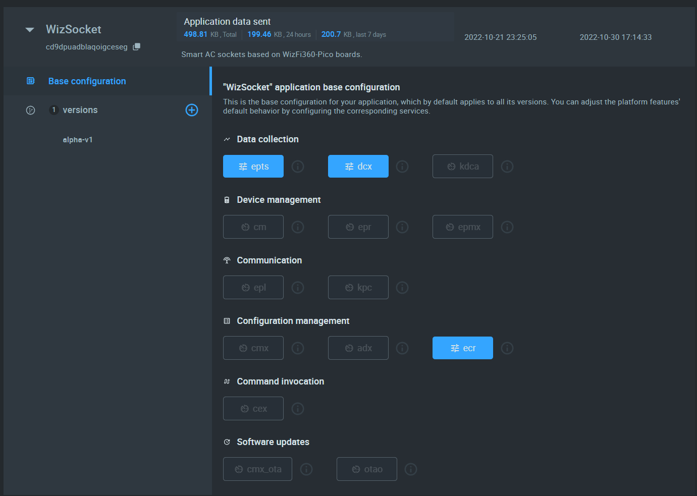
Here you can see items like epts, dcx, ecr etc. All these are endpoint application modules that allow you to collect, respond, process, deploy, and update all your IoT devices. These tools are really powerful and you can customize them in so many ways.
EPTS is responsible for basic data collection. It will capture all data sent by an IoT device. Click on it to configure.
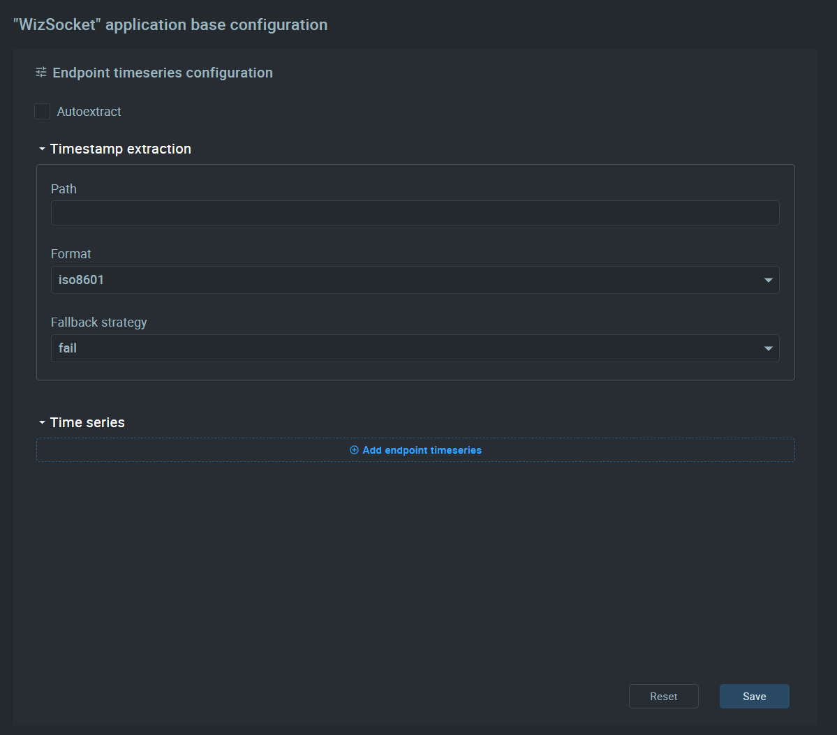
Change the settings to what is shown above. We are simply creating a time series for collecting data. That means all data sent by an IoT device is saved to a database along with the timestamp. This allows you to visualize data on a time graph which is what we need for WizSocket.
Next is configuring DCX. It is a module that allows you to send data and commands to the IoT device. This is similar to sending MQTT topic messages. You can include raw data or JSON objects along with your commands.
Now click on one of the versions under Base configuration. In Kaa you can create different versions of the same app but with different configurations. I have named the first version as alpha-v1. Based on your selection, some modules may remain active or inactive.
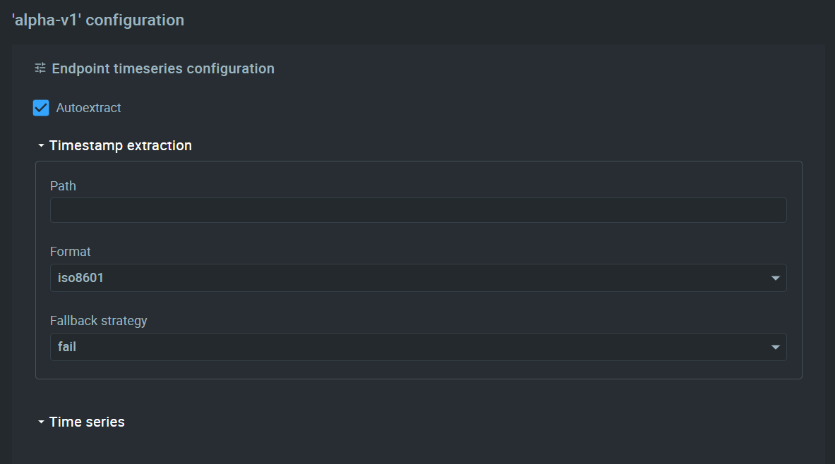
In the EPTS configuration (version-specific), you can configure it to Autoextract the time series data as shown below.
Now go to the EPMX module configuration. This module allows you to extend the metadata associated with your device. Metadata is any parameter that is statically assigned to your device. This can be, for example, the current location of the device. For WizSocket we need to create one metadata called load_state. This will keep track of the output load state of the WizSocket device.
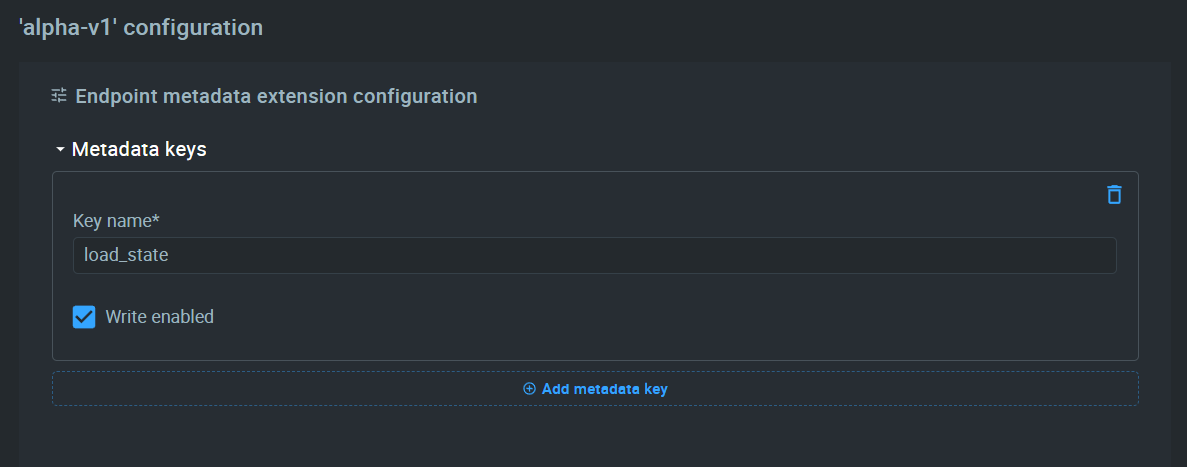
We should enable to Write enabled option so that we can change its value of it from the device remotely.
Save that configuration and click on the EPL module. This module allows us to keep track of the device life cycle-related parameters. Life cycle simply tells the Kaa IoT application what to do when the device is available or not available or what happens in specific situations. For example, if the device goes offline for more than a period, you can execute some tasks.
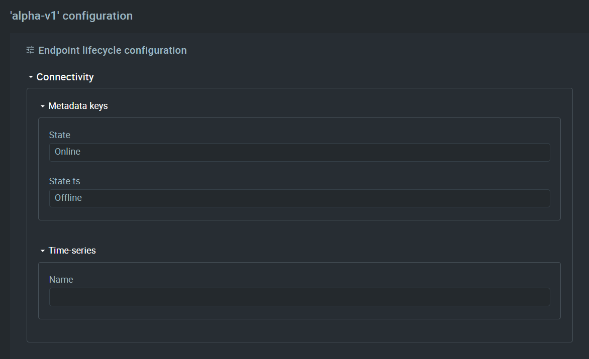
Above, we are adding two state indicators Online and Offline. If the device is online (connected to the server), we will show the status as Online. Otherwise, the status Offline will be shown automatically. You must save all configurations before exiting. You can leave the rest of the modules as is.
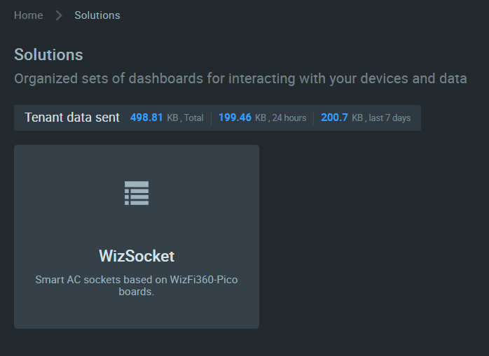
Now we need to create a Solution. In Kaa terms, a Solution is the front-end of your IoT device/application. A solution is a collection of dashboards. So the Solution itself is not the dashboard. Go to the Solutions tab and add a new solution.
Add details such as a description and create it. For WizSocket, we will create a Solution called "WizScoket".
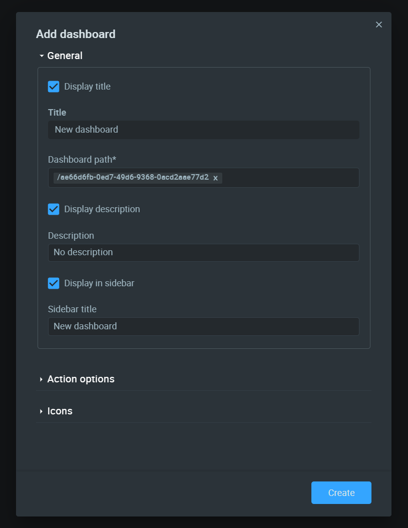
Now inside the new Solution, we need to create a dashboard. Click on the Solution to open the dashboard and create a new one.
Add name and description to your new dashboard. We will name it "Real-time Monitoring".
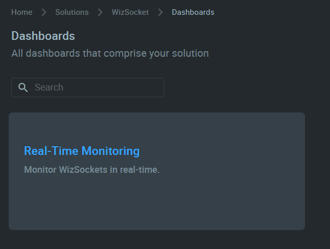
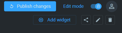
Your new dashboard will be empty when created. Click on the Edit mode button to edit your dashboard.

Then click the Add widget button to start adding widgets.
Kaa has many in-built widgets that will suit most of your applications.
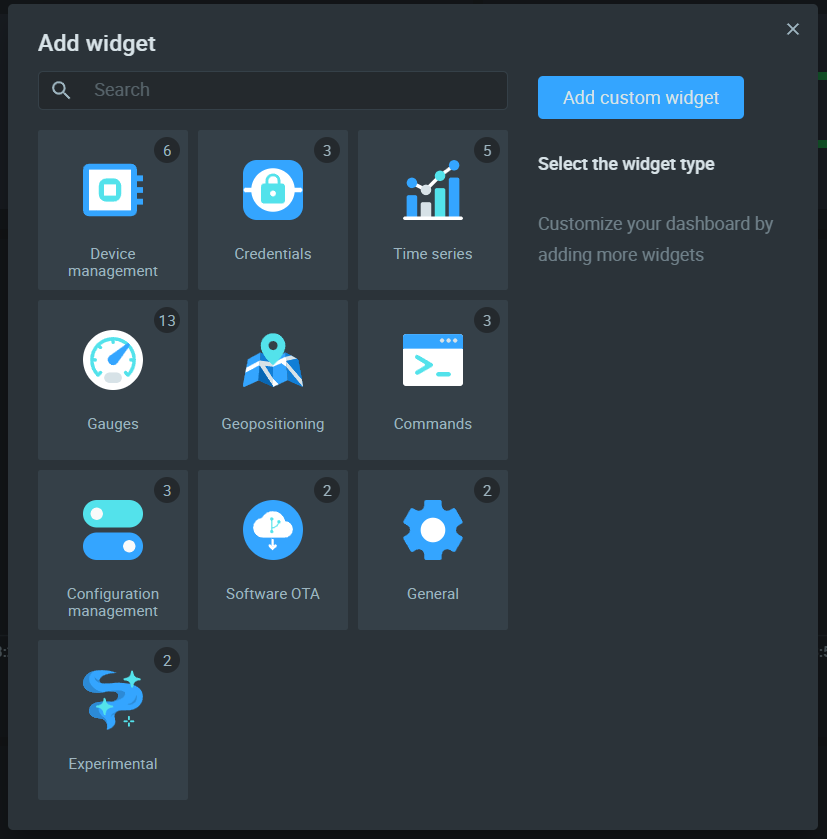
Let's start by adding a Commands widget for showing the status of the device as well as controlling the load connected to the WizSocket.
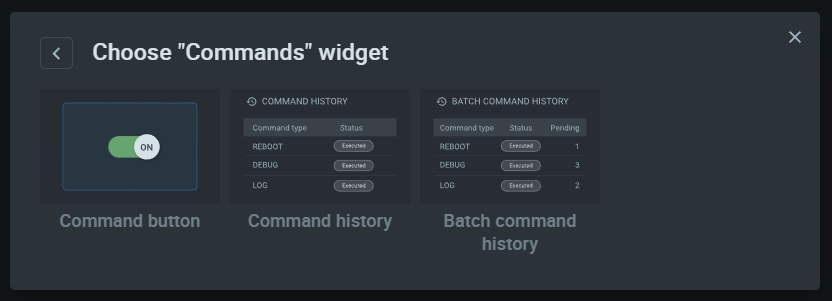
Choose Command button from the list. This widget allows to us send commands (MQTT topic updates) to the device and read the response. This happens through the DCX (Data and Command) module of Kaa. We will create a new command widget called "Load Status".
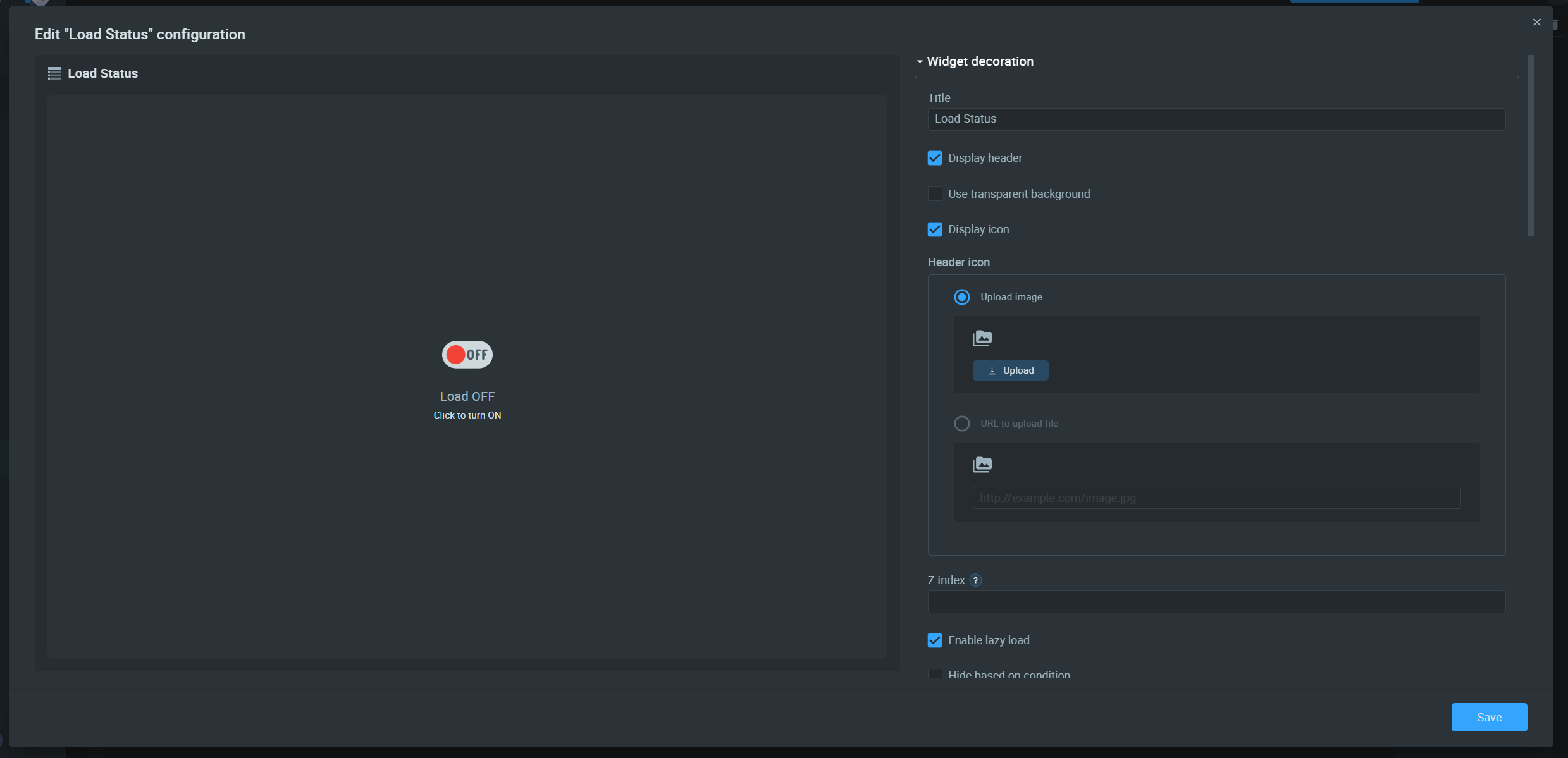
We have three types of configurations for a command widget.
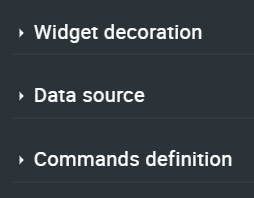
For the Widget decoration, simply add descriptions, icons etc.
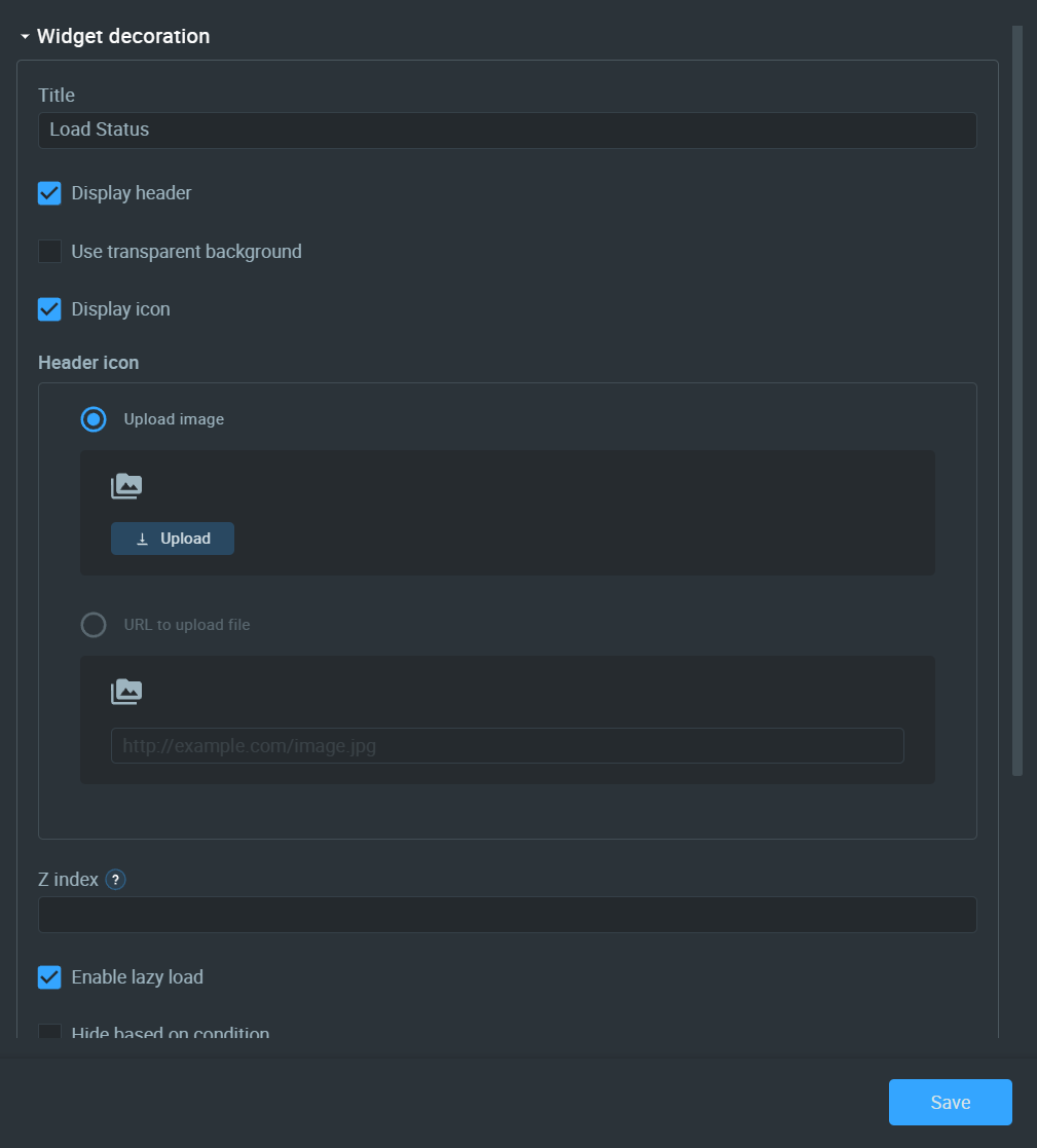
For the Data source configure it as similar to below.
Now configure the Commands definition as below.
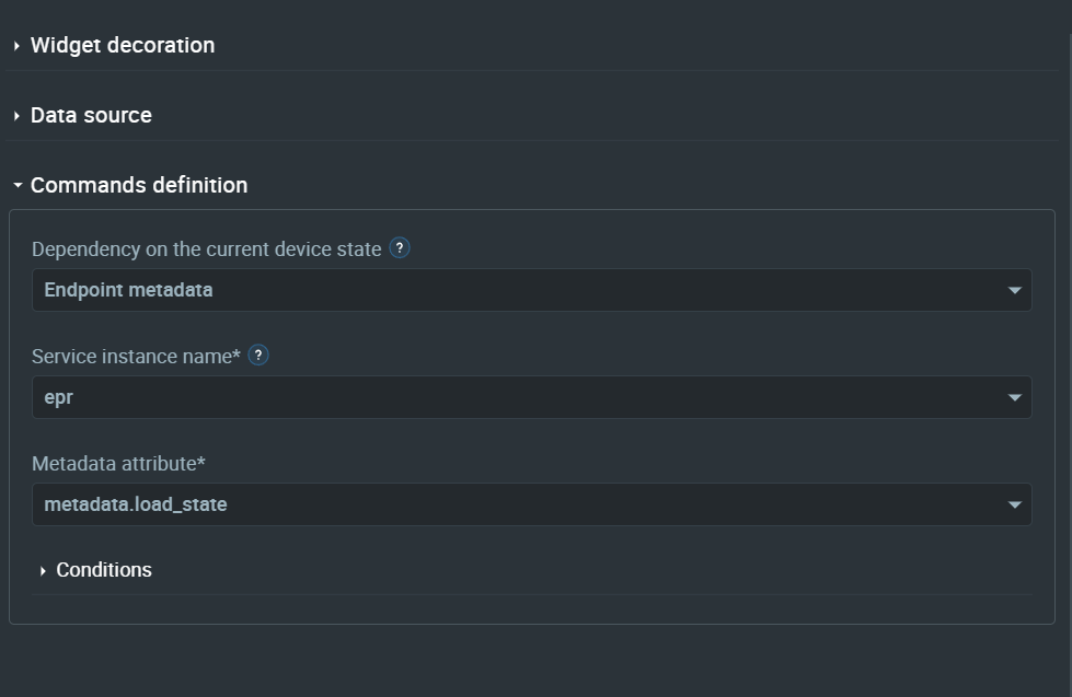
Select the load_state metadata key from the list of attributes. This will allow us to read or write that metadata value.
For the Conditions, add the following.
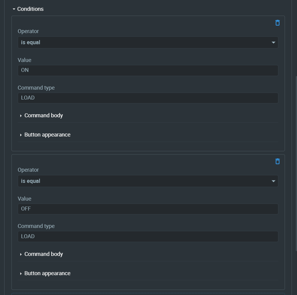
We are checking the status of the load_state key with two boolean operators and sending a command based on it. If the value of load_state is ON, we will send a command and if it is OFF, then we send another command. In this case, the command is called LOAD but its value will change each time we send it. This has the effect of toggling a button.
For the appearance of the first condition, I am setting the button to the following image of an ON toggle button.
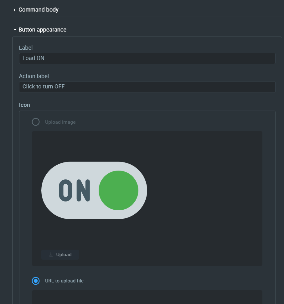
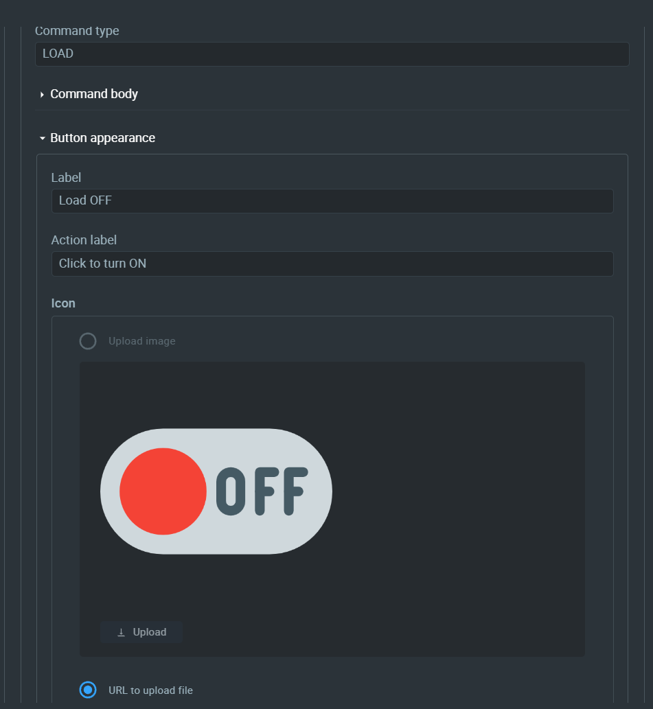
Next, set the appearance for the next condition. You can use any images in these places.
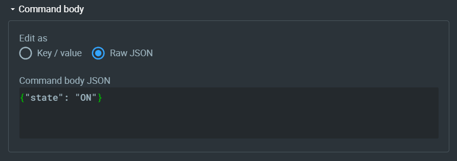
The Command body of the first condition (ON condition) should be the following.
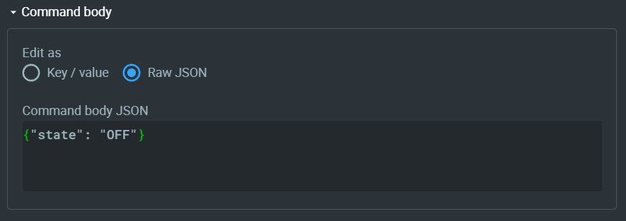
And for OFF condition, it should be the following.
Now you will get something like the following. The button image may be different depending on what you set. It is best to use PNG images for the buttons.
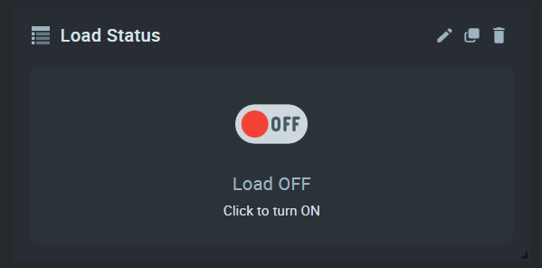
When you press this widget (after exiting from Edit mode), the command associated with the current state will be sent to the IoT device, in this case, the WizSocket device. If the button is ON, then it will send OFF command. If it is OFF, then it will send the ON command. In both cases, the command is the same LOAD but the JSON data is different as we have seen above.
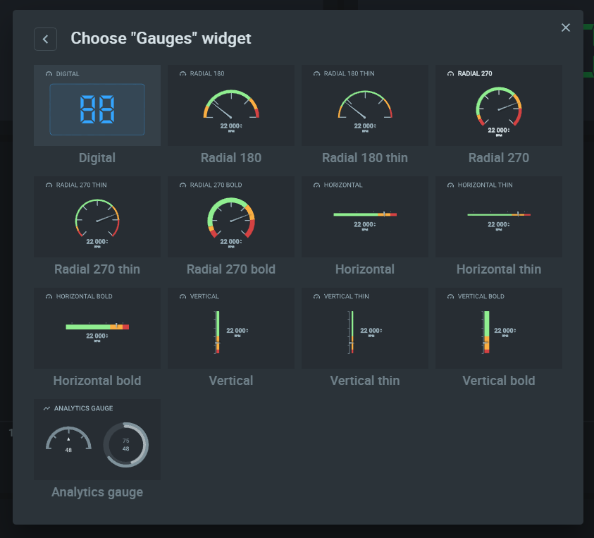
Next, we need to add the voltage, current, and power monitors. For this, select the Digital widget from the Gauges collection.
Press the Edit button to edit the widget.
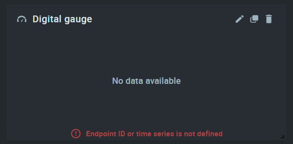
Similar to the Commands widget, we have multiple sets of customization for the Digital gauge widget.
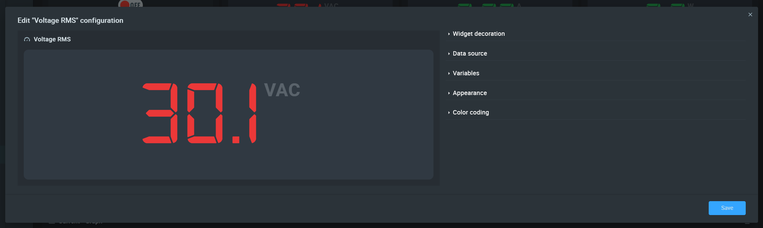
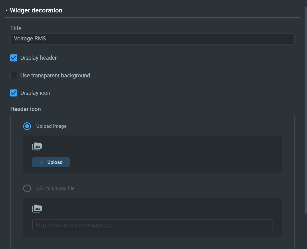
For the Widget decoration, just give it some name and an image if you like.
For the Data source, configure it as below.
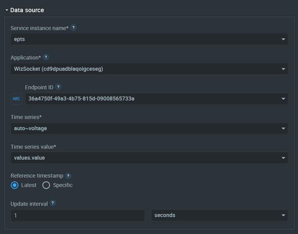
You just need to choose which value from the time series you need to show in the widget. auto~voltage means automatically captured/extracted time series data. Remember we have configured the EPTS to Autoextract? The data will show up here. For the first time, you may not see these values since EPTS has not captured anything yet. So simply run the WizSocket device and allow it to send some data first. Then the time series will appear on the dashboard list.
For the Variables, we don't need anything. For the Appearance, you can configure it as below.
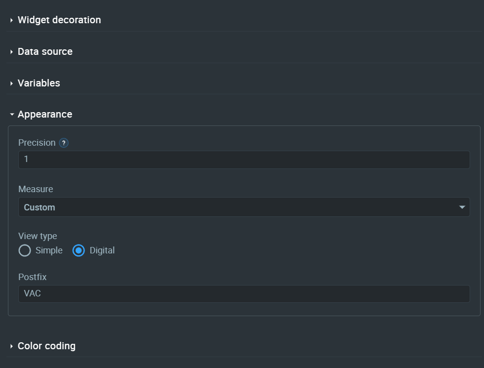
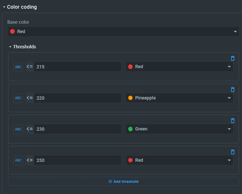
For Color coding, I have put the following values. This allows us to show different colors in different ranges.
Similarly, you can create Digital gauge widgets for Current and Power or any other value you like.
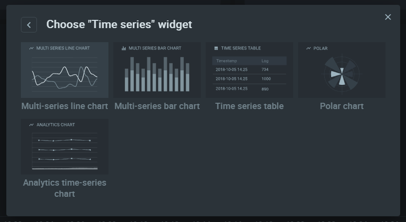
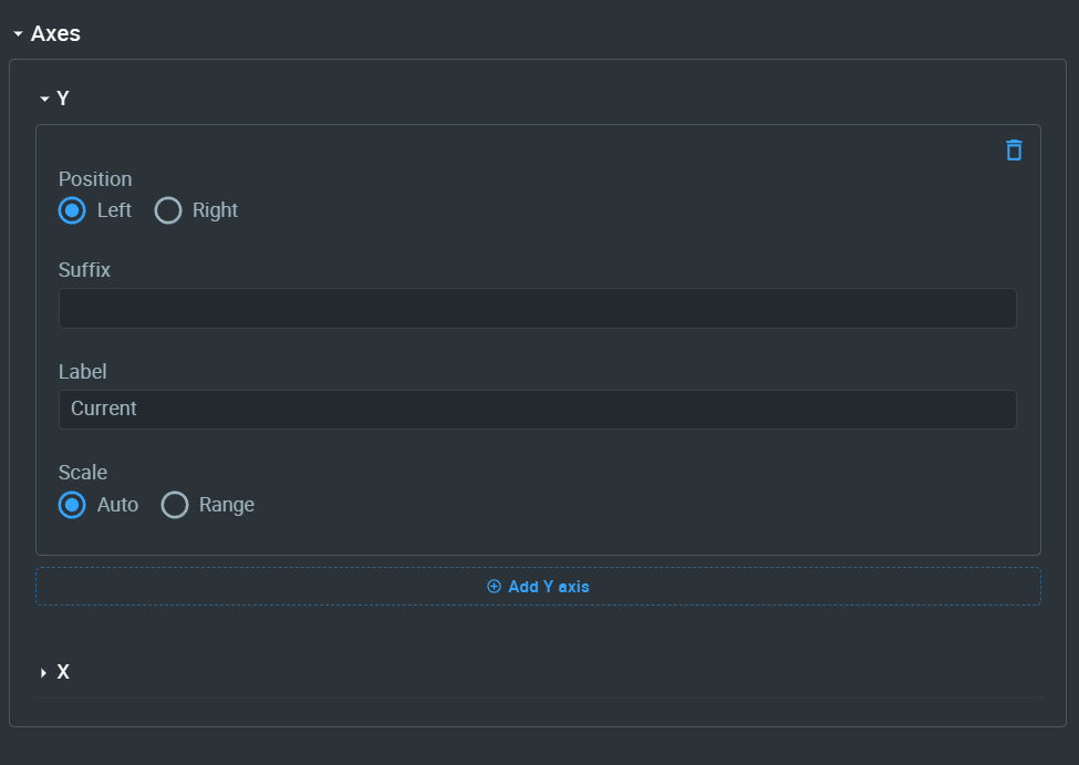
Next, we can add Graph widgets to visualize time series data. In our case, the time series data includes voltage, current, power and load status.
Then configure it as below for showing only RMS current.
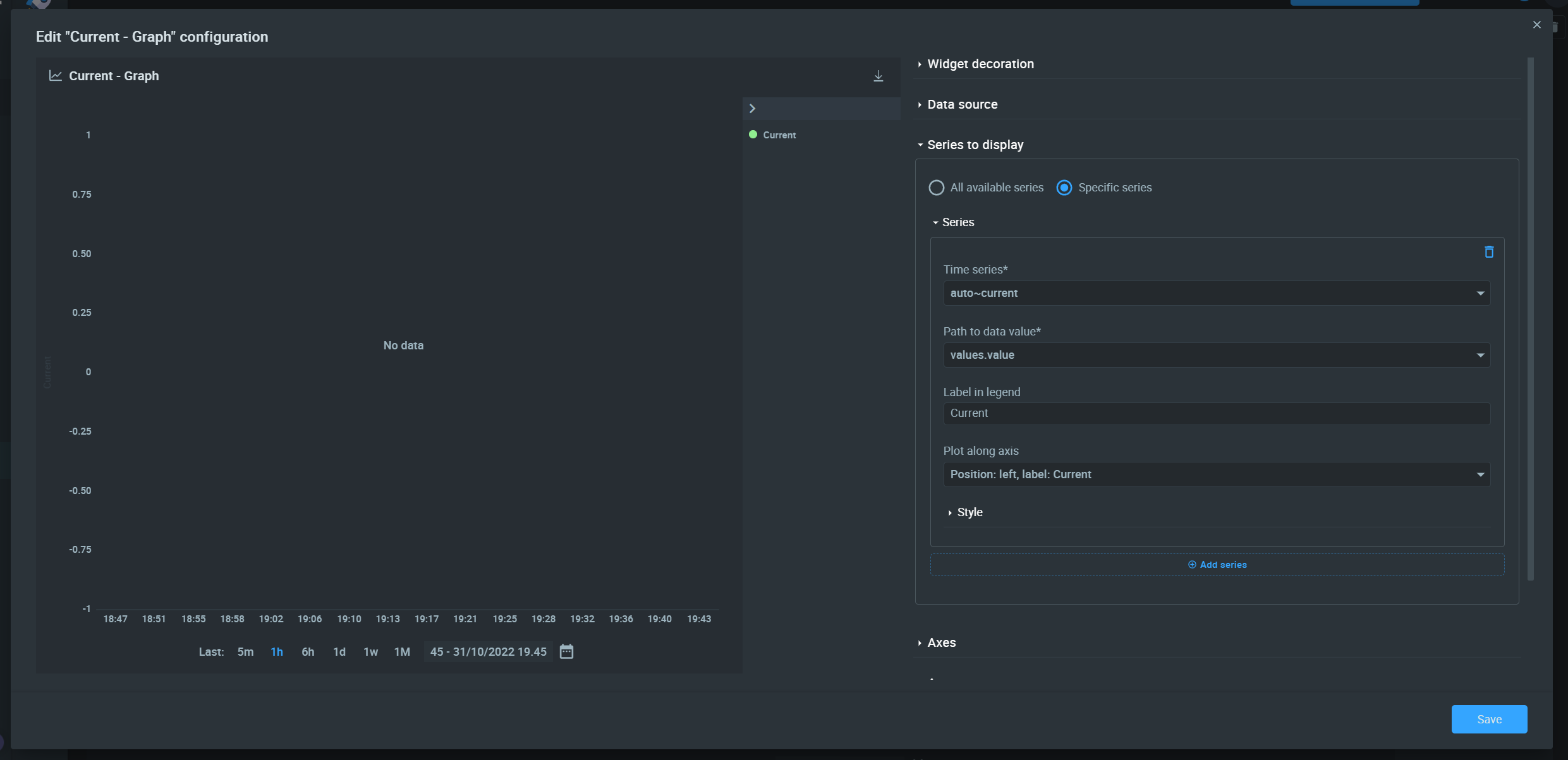
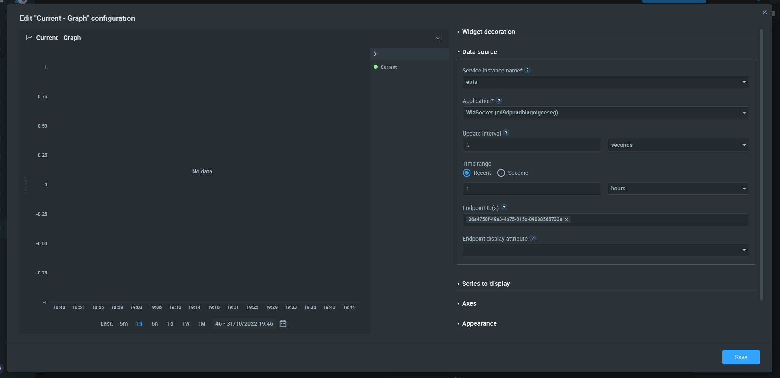
You will get a graph like below.
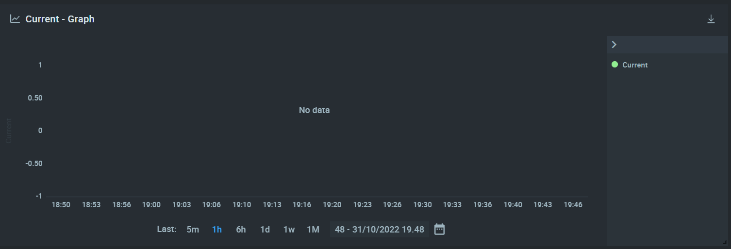
Now replicate the same for other parameters. Once you power on the device and the device gets connected to the IoT server, you will see data on these graphs.
Finally, save the dashboard by flipping the Edit button and publishing the changes. Your IoT dashboard is ready. Kaa has so much more features and tools which we will cover as the development of the next version of WizSocket progress.
Device Assembly
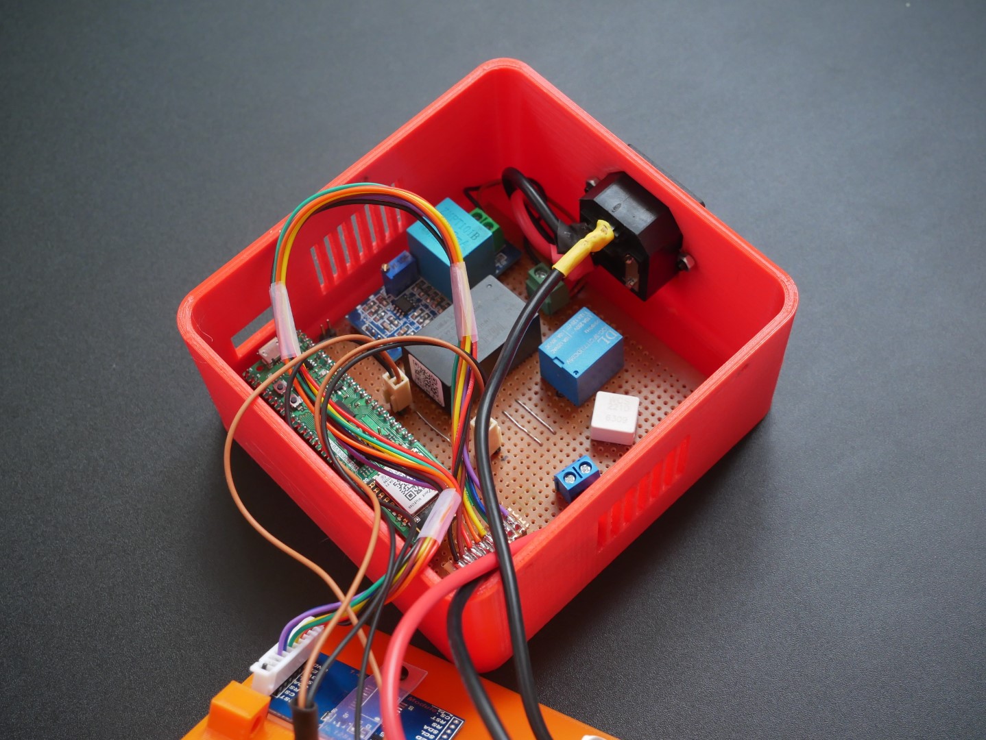
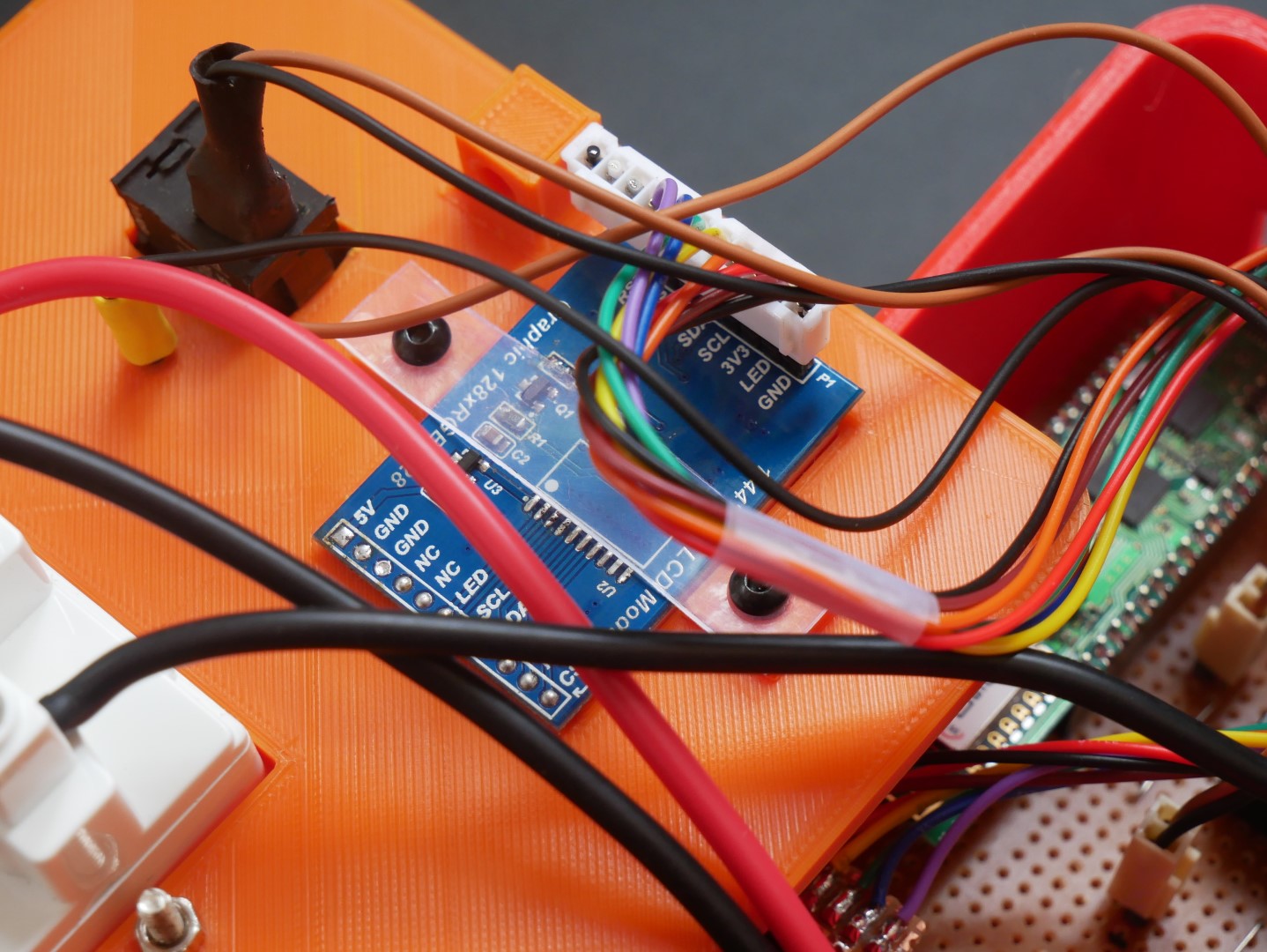
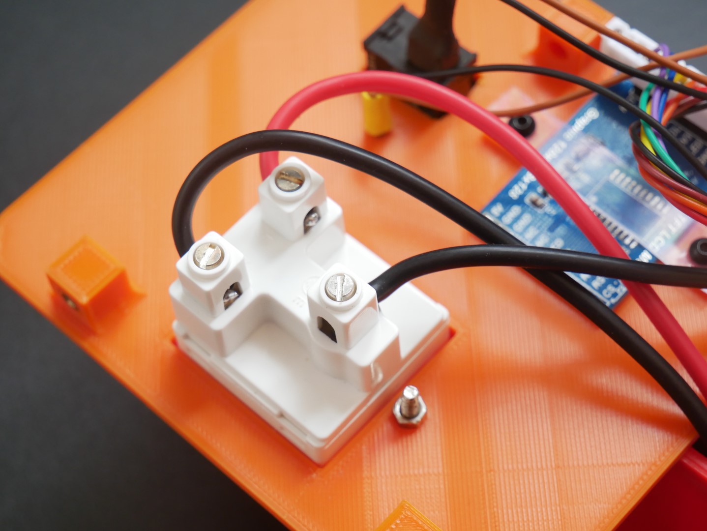
Since this is a prototype, I did not opt for a dedicated PCB. Instead, I went with a regular perfboard. This is also because I can verify the working of many of the modules used in this project. All components were soldered onto the perfboard by hand.
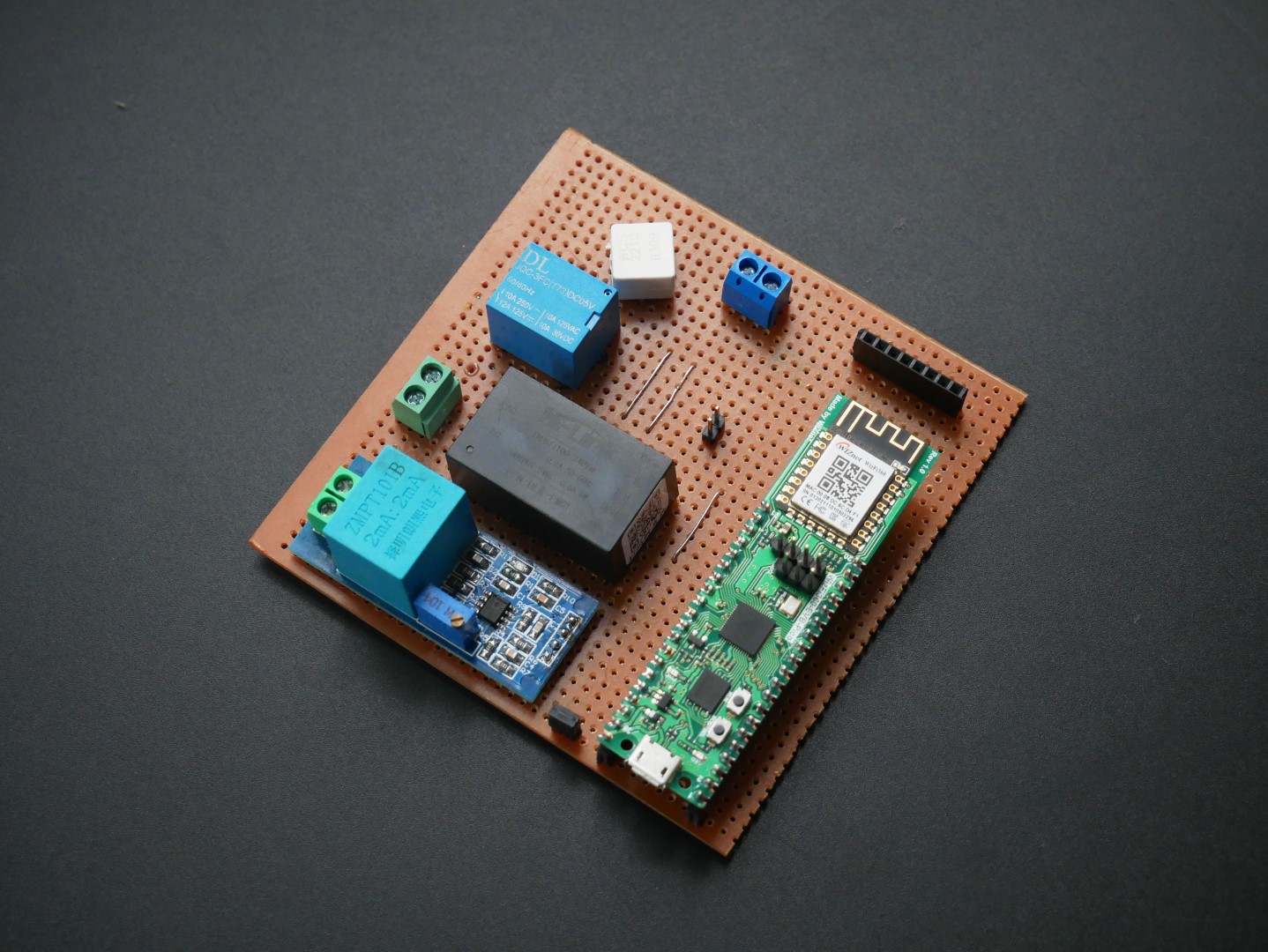
I got the 3D prints done at Sparx3D in Ernakulam. The brass inserts were easily added to the enclosure pieces with the help of a soldering iron. Since we are using connectors for everything, we can assemble and disassemble everything easily in case we want to make any modifications.

Working Video
What's Next
Since this is the first V1 prototype of WizSocket, we need to improve many things in the next version.
- Designing a custom PCB with WizFi360-PA module and RP2040.
- Making the device enclosure smaller.
- Adding timer feature.
- Adding threshold features to automatically disconnect the load in the event of faults.
- Smartphone app.
-
WizSocket Firmware
Link to WizSocket firmware for WizFi360-EVB-Pico.

-
WizSocket V1 Enclosure
Fusion 360 3D file

-
WizSocket V1 KiCad Schematic