rp2040-dmxsun
RP2040-based USB DMX dongle with integrated web server

What is it?
The rp2040-dmxsun is a multi-purpose DMX-512-A toolbox to control stage lighting systems. It's most common use-case is to transmit the DMX data generated on a PC, Raspberry Pi or similar in a format that the lighting fixtures on stage can understand. In the most simple case, it's an USB-DMX interface.
DMX-512-A works in networks called universes and each universe can contain up to 512 slots of data. dmxsun can transmit up to 16 universes, meaning you can control 8192 slots of DMX data at the same time.
Dmxsun is usually connected to its host via a single USB connection that also powers the device. To the computer, the dmxsun device looks like a network card (it uses the CDC NCM interface) and the integrated DHCP-server assigns an IP-address to the host machine so they can talk to each other.
To find out dmxsun's IP address, have a look at your kernel log on Linux (run dmesg) or hover over the Disconnect USB device icon in Window's task bar or check the network device properties on macOS.
You can browse to this IP address in your web browser to access the integrated web server or you can send ArtNet or E1.31/sACN packets to the IP address to make dmxsun send this data as DMX data.
Furthermore, you can attach an nRF24 radio module to the base board to send or receive up to 4 universes wirelessly to or from another dmxsun device. That also means that the device can also work stand-alone, receiving DMX data from another dmxsun device and outputting it on local ports.
Why is it called dmxsun?
The idea came when thinking about a suitable icon for the pages on the integrated web server. You can think about the dmxsun as being a central device and 16 rays of light coming out of it.
Sun could also be seen as an acronym for sixteen universes :D
Maybe it's also because outdoor lighting technicians absolutely love the sun since they can perfectly set up their light show while the sun is shining bright ;)
What does it look like?
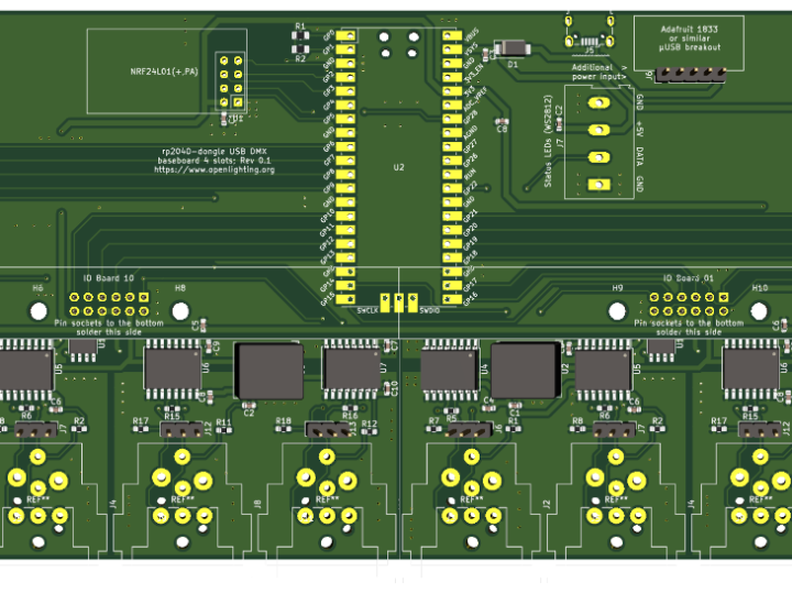
The hardware consists of a base board into which the Raspberry Pi Pico-board plugs in to. To get a quick overview of the board's status, 8 RGB status LEDs are attached to the base board.
Attached to this base board can be 0 to 4 IO boards that carry the actual RS-485 drivers and XLR connectors:
If all 4 IO boards are attached to the base board, you can have 16 output ports fitting into 1U of an 19" rack:
How is configuration data handled?
The complete configuration of the device, including IP address, patching and wireless configuration can be stored on any of the IO boards or on the base board.
When the device powers up, it scans the 4 IO board slots in order for connected boards and the configuration stored on them. As soon as a valid and non-disabled configuration is found, it is loaded and used. If no IO board has a valid configuration, it tries to load the config from the flash memory of the Pico board. If this also doesn't seem valid, a fallback configuration is applied.
The status LEDs on the base board indicate which IO boards have a valid configuration and which configuration is currently active.
All the configurations can be managed via the integrated web server.


