
How to Add Wired Ethernet with W5500 on an STM32H563 Universal Control Board?
The UCB_board project is a work-in-progress STM32H563VIT6 control board for SCPI, UART, USB, RS485, and wired Ethernet experiments in a 3U Eurocard form factor.

WIZnet - W5500
x 1
Summary
The UCB_board project is a work-in-progress STM32H563VIT6 control board for SCPI, UART, USB, RS485, and wired Ethernet experiments in a 3U Eurocard form factor. WIZnet W5500 is used as the board’s 10/100 Ethernet controller, giving the STM32H5 MCU an SPI-connected network interface with a hardware TCP/IP stack rather than relying on the MCU’s internal Ethernet MAC or a software-only TCP/IP path.
What the Project Does
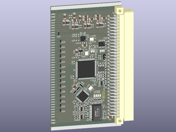
UCB_board is a universal control board intended for testing instrument-control and communication concepts. The README identifies the target feature set as SCPI, UART, USB, RS485, and Ethernet, built around an ARM Cortex-M33 STM32H563VIT6 MCU in LQFP100 package. The board also follows a 3U Eurocard mechanical format, which makes it closer to bench, rack, and modular control hardware than a small maker breakout board.
The repository contains hardware design files, production outputs, a schematic PDF export, a BOM, Gerbers, and a CubeMX .ioc firmware configuration. At this stage, the project status is marked as schematic and PCB design, so the Ethernet implementation is verified mainly from hardware design and CubeMX pin configuration rather than complete application firmware.
Where WIZnet Fits
WIZnet W5500 is the Ethernet subsystem for the board. The README explicitly lists “10/100 Ethernet (based on WIZnet W5500),” and the KiCad schematic defines an Interface_Ethernet:W5500 symbol with value W5500, LQFP-48 footprint, and the description “10/100Mb SPI Ethernet controller with TCP/IP stack.”
Architecturally, the W5500 sits between the STM32H563 and the Ethernet connector/magnetics path. The STM32 communicates with the W5500 over SPI2, while W5500 handles Ethernet framing and TCP/IP socket processing internally. That is a good fit for a multi-interface control board because the MCU can spend more time on command parsing, RS485, USB, timing, and board-management logic instead of running the full TCP/IP stack in firmware.
The design uses the W5500 as a discrete Ethernet controller, not as an integrated MCU-plus-Ethernet part. For this board format, that choice makes sense: STM32H563 remains the central controller, while W5500 provides a predictable, SPI-controlled wired network interface with hardware socket offload, internal buffering, and stable cabling behavior.
Implementation Notes
The available firmware evidence is a CubeMX configuration file, not finished C application code. The repository does verify how the STM32 is wired and configured for W5500 control.
firmware/UCB_board.ioc configures the W5500 SPI bus and chip-select line:
PB12.GPIO_Label=W5500_CS
PB12.Signal=GPIO_Output
PB13.GPIO_Label=W5500_SCK
PB13.Signal=SPI2_SCK
PB14.GPIO_Label=W5500_MISO
PB14.Signal=SPI2_MISO
PB15.GPIO_Label=W5500_MOSI
PB15.Signal=SPI2_MOSI
This matters because W5500 is controlled through SPI. PB13, PB14, and PB15 map the STM32H563 SPI2 bus to the W5500 clock, MISO, and MOSI signals, while PB12 is a firmware-controlled chip-select output.
The same CubeMX file also assigns reset and interrupt pins for the Ethernet controller:
PD8.GPIO_Label=W5500_RST
PD8.Signal=GPIO_Output
PD9.GPIO_Label=W5500_INT
PD9.Signal=GPIO_Input
SPI2.CalculateBaudRate=11.764705 MBits/s
SPI2.Mode=SPI_MODE_MASTER
This matters because a robust W5500 design normally needs deterministic reset control and a way to detect socket/link-related events without constantly polling. The SPI2 bus is configured as master, with the generated CubeMX baud-rate calculation shown as about 11.76 Mbit/s.
The production BOM confirms the Ethernet controller as an assembled component:
U1;W5500;Package_QFP:LQFP-48_7x7mm_P0.5mm;
10/100Mb SPI Ethernet controller with TCP/IP stack, LQFP-48;1
The BOM also includes an H1102NL Ethernet transformer, indicating that the design is not only a logical SPI connection but a board-level wired Ethernet implementation with magnetics support.
Practical Tips / Pitfalls
- Keep the W5500 SPI traces short and route SCK cleanly; the current CubeMX configuration shows SPI2 at about 11.76 Mbit/s, but W5500 designs can become signal-integrity sensitive as SPI speed increases.
- Treat
W5500_RSTas a required firmware-controlled signal, not a decorative pin. Reset sequencing should happen before socket initialization. - Use
W5500_INTwhen implementing firmware so the MCU does not need to poll socket status continuously. - Verify the Ethernet magnetics and RJ45 path during bring-up. The BOM includes an H1102NL transformer, so PHY-side layout and termination are part of the Ethernet reliability story.
- Decide early whether the control protocol will use DHCP or static IP. Instrument-control boards often benefit from static addressing, while lab networks may prefer DHCP.
- Plan W5500 socket allocation before writing SCPI-over-TCP firmware. W5500 provides multiple hardware sockets, but a control board can consume them quickly if it exposes command, debug, telemetry, and update channels.
- Add watchdog recovery around link loss, socket timeout, and SPI transaction failure. A rack-style control board should recover without manual power cycling.
FAQ
Q: Why use W5500 on this STM32H563 board?
A: W5500 gives the board a dedicated 10/100 wired Ethernet controller with a hardware TCP/IP stack. That reduces the amount of network-stack work the STM32H563 firmware must handle, which is useful on a board that also needs USB, UART, RS485, SCPI-style command handling, and board-control logic.
Q: How does W5500 connect to the STM32H563 in this project?
A: The repository configures W5500 on SPI2: PB13 is SCK, PB14 is MISO, PB15 is MOSI, and PB12 is chip select. PD8 is assigned as W5500 reset, and PD9 is assigned as W5500 interrupt input.
Q: What role does W5500 play in this specific board?
A: W5500 is the wired Ethernet interface for the Universal Control Board. It gives the STM32H563 a TCP/IP-capable Ethernet path that can be used later for SCPI-over-TCP, remote control, telemetry, configuration, or firmware-management services.
Q: Can beginners follow this project?
A: It is better suited to intermediate hardware and firmware developers. The repository includes KiCad hardware files, production outputs, a BOM, and an STM32CubeMX configuration, but it does not currently provide a complete W5500 application firmware example.
Q: How does W5500 compare with using the STM32 Ethernet MAC and LwIP?
A: STM32 MAC plus LwIP can provide tight integration but requires more firmware-side TCP/IP stack configuration, RAM allocation, and driver work. W5500 moves TCP/IP socket handling into the Ethernet controller, which can simplify firmware for a control board whose main purpose is multi-interface instrumentation rather than network-stack development.