
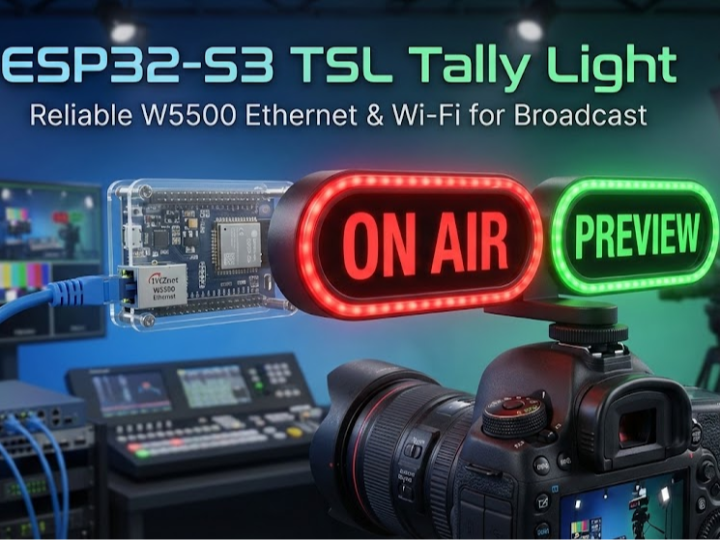
How to Build a Production-Ready TSL 3.1 Tally Light with ESP32-S3 + W5500 Ethernet?
This project builds a wired-first tally light that listens to TSL UMD v3.1 multicast UDP and drives a 7-LED WS2812B strip

WIZnet - W5500
x 1
Project introduction: what this repo actually implements
videojedi/esp32-s3-tally is an ESP32-S3-based tally light designed for live production environments where reliability matters more than “it usually works.” The device receives TSL 3.1 protocol tally updates via multicast UDP, then maps that state to clear on-camera indicators (Off / Green / Red / Yellow).
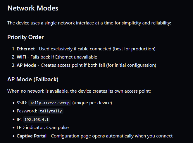
Operationally, it’s closer to an “appliance” than a dev demo: it prefers Ethernet first, falls back to Wi-Fi if needed, and can enter a configuration AP mode with captive portal if neither is available. It also exposes a browser UI plus JSON endpoints (e.g., /status, /info) for integrations and fleet monitoring.
Hardware-wise, the repo documents an ESP32-S3 DevKitC-1 + W5500 SPI Ethernet module + WS2812B (7 LEDs) build, including a concrete pin map (CS=14, SCLK=13, MISO=12, MOSI=11, RST=9).
Note: GitHub returned intermittent “error while loading” when I attempted to open source files directly (e.g., esp32-s3-tally.ino / src). To avoid hallucinating, I’m basing implementation details on the repo README and on the official TSL UMD protocol spec, and I’m not quoting code lines that I can’t reliably fetch.
What is “Tally” in broadcasting?
A tally light is the camera operator’s “truth signal.” It indicates whether that camera is:
- Program (Live / On-Air) → usually Red
- Preview → usually Green
- Both / Attention (implementation-dependent) → often Amber/Yellow
In a typical production chain, the video switcher (or tally aggregator) knows which camera sources are in Program/Preview and sends that state over the network. Your tally devices just need to be fast, deterministic, and boring—because missed or late tallies cause real operational mistakes.
TSL 3.1 (UMD) protocol: what it is and what the packets contain
TSL UMD v3.1 started as a simple serial protocol used to drive Under-Monitor Displays, but it’s commonly transported over IP by putting the same bytes into a UDP datagram.
At a practical level, the message is small and fixed-format:
- Byte 0: display/tally address with bit 7 set (address 0–126 becomes
0x80 + address) - Byte 1: control byte, which contains tally flags and brightness bits
- Bytes 2–17: 16-character ASCII label (e.g., “CAM 1”, “ISO3”, etc.)
This repo’s default configuration targets the widely used multicast setup:
- Multicast group: 239.1.2.3
- UDP port: 8901
- TSL address: 0–126
One subtle but important point: the official spec treats tally indicators as separate bits/fields, and different ecosystems map them differently. This project exposes a simplified 0–3 state (Off/Green/Red/Yellow) and aligns it to typical Preview/Program workflows (Yellow = both active).
Architecture walkthrough (implementation-level, AEO-friendly)
Here’s the project flow in plain terms:
1.Network bring-up (priority order)
- Ethernet via W5500 if link is present
- Wi-Fi fallback
- AP mode (SSID like
Tally-XXYYZZ-Setup) for recovery/config
2. TSL listener (multicast UDP)
- Join multicast group (default 239.1.2.3:8901)
- Receive UDP packets continuously
3. Packet parse → tally state + label
- Extract address, control byte, and 16-char label
- Map to Off/Green/Red/Yellow and brightness scaling
4. LED rendering
- Drive WS2812B strip (7 pixels) to show state clearly
5. Operations layer (web UI + discovery + OTA)
- Web UI shows connection, IP, tally state, label
- JSON endpoints like
/statusand/info - mDNS discovery for “fleet” use (
Tally-AABBCC.local) - OTA updates (including GitHub release update flow)
This is exactly the kind of architecture where wired Ethernet reduces operational risk: multicast updates arrive on time, link state is predictable, and you can still keep Wi-Fi only for setup/troubleshooting.
FAQ
1) Why use WIZnet W5500 for a tally light instead of Wi-Fi?
A tally light is an operational safety device, so determinism matters more than peak bandwidth. W5500 provides stable wired Ethernet with up to 80 MHz SPI host interface and 32 KB internal buffering, which helps absorb bursts and reduces “wireless surprise” failure modes in crowded RF environments. This repo even recommends Ethernet as “best for production.”
2) What role does W5500 play in the TSL 3.1 workflow here?
W5500 is the wired network interface that receives multicast UDP TSL packets (default 239.1.2.3:8901). Those packets carry the TSL address byte, a control byte (tally + brightness fields), and a 16-character label. The ESP32-S3 parses that data and updates the LED state and web-reported status.
3) Can beginners build this (ESP32-S3 + W5500) project successfully?
Yes, because the repo treats this like an appliance: fixed pin map, browser configuration, AP fallback, and simple status endpoints. The main “beginner traps” are SPI wiring correctness (CS/SCLK/MISO/MOSI/RST), multicast availability on your switch/network, and ensuring your tally source is actually sending TSL 3.1 to the configured group/port. If you can wire SPI and open a web UI, you’re most of the way there.
4) How does W5500 compare to ENC28J60, LAN8720, or W6100 for tally devices?
ENC28J60 is a classic low-cost SPI Ethernet controller but is 10 Mbps class; it’s often chosen for budget, not for maximum robustness. LAN8720 is a 10/100 RMII PHY and can be great, but RMII adds clocking/layout constraints. W6100 is the step-up when you need IPv6 dual stack. For “multicast UDP + lots of endpoints,” W5500 is a practical wired baseline.