
BetterFrame ioBOX: A PoE-Powered ESP32-S3 + WIZnet W5500 IO Controller for Smart Display Systems
BetterFrame ioBOX: A PoE-Powered ESP32-S3 + WIZnet W5500 IO Controller for Smart Display Systems

WIZnet - W5500
x 1
Introduction
Most digital signage and camera-wall systems treat physical IO as an afterthought — a webhook, maybe a relay board bolted to the side of a server rack. BetterFrame takes a different approach. Alongside its Raspberry Pi 5 display engine, the project ships a purpose-built IO controller called the ioBOX: an ESP32-S3 board with WIZnet W5500 Ethernet, 802.3af PoE input, four USB-A host ports for HID devices, RS-485, and GPIO expansion — all on a single RJ-45 cable.
This article focuses on the ioBOX hardware and firmware design, with a general overview of the BetterFrame system it connects to. The full project is open-source at github.com/BetterCorp/BetterFrame, dual-licensed under AGPL-3.0 or a commercial licence from BetterCorp.
BetterFrame in Brief
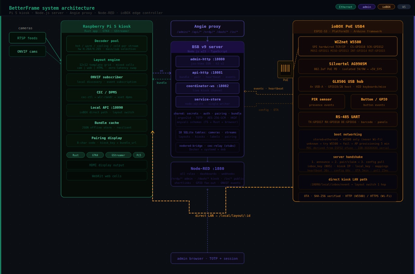
BetterFrame is a multi-camera display management system built for Raspberry Pi 5. It manages RTSP and ONVIF camera streams in flexible grid layouts, supports up to 32 cameras per display, and provides a full web-based admin UI. A native Rust kiosk application (GTK4 + GStreamer) runs on the Pi and owns the hardware video decoder pool directly — the reason layout switches have zero perceived latency. The server is TypeScript/Node.js built on the BSB v9 plugin framework, with SQLite for persistence, htmx for the admin UI, and Node-RED for automation rules and dashboard content.
The system separates concerns cleanly: the server coordinates, the kiosk renders, and — the subject of this article — the ioBOX handles physical IO at the edge.
What the ioBOX Does
The ioBOX sits on the same LAN as a BetterFrame kiosk and acts as a physical-world bridge. It detects events — motion from a PIR sensor, a button press, a barcode scan over RS-485, a USB keyboard or HID controller — and translates them into structured events that trigger layout switches, Node-RED flows, or custom automation rules.
A concrete example: a visitor walks into a lobby. The PIR sensor on the ioBOX fires a presence event. That event matches an IO mapping on the server, which calls the kiosk's local API directly over LAN, switching the display from an idle screensaver layout to the active welcome layout — in one network hop, without routing through the server at all.
The ioBOX comes in two firmware builds:
iobox_wifi— provisions over a captive AP, then connects as Wi-Fi STA.iobox_eth— uses WIZnet W5500 hardwired Ethernet. If Ethernet succeeds at boot, Wi-Fi is never enabled.
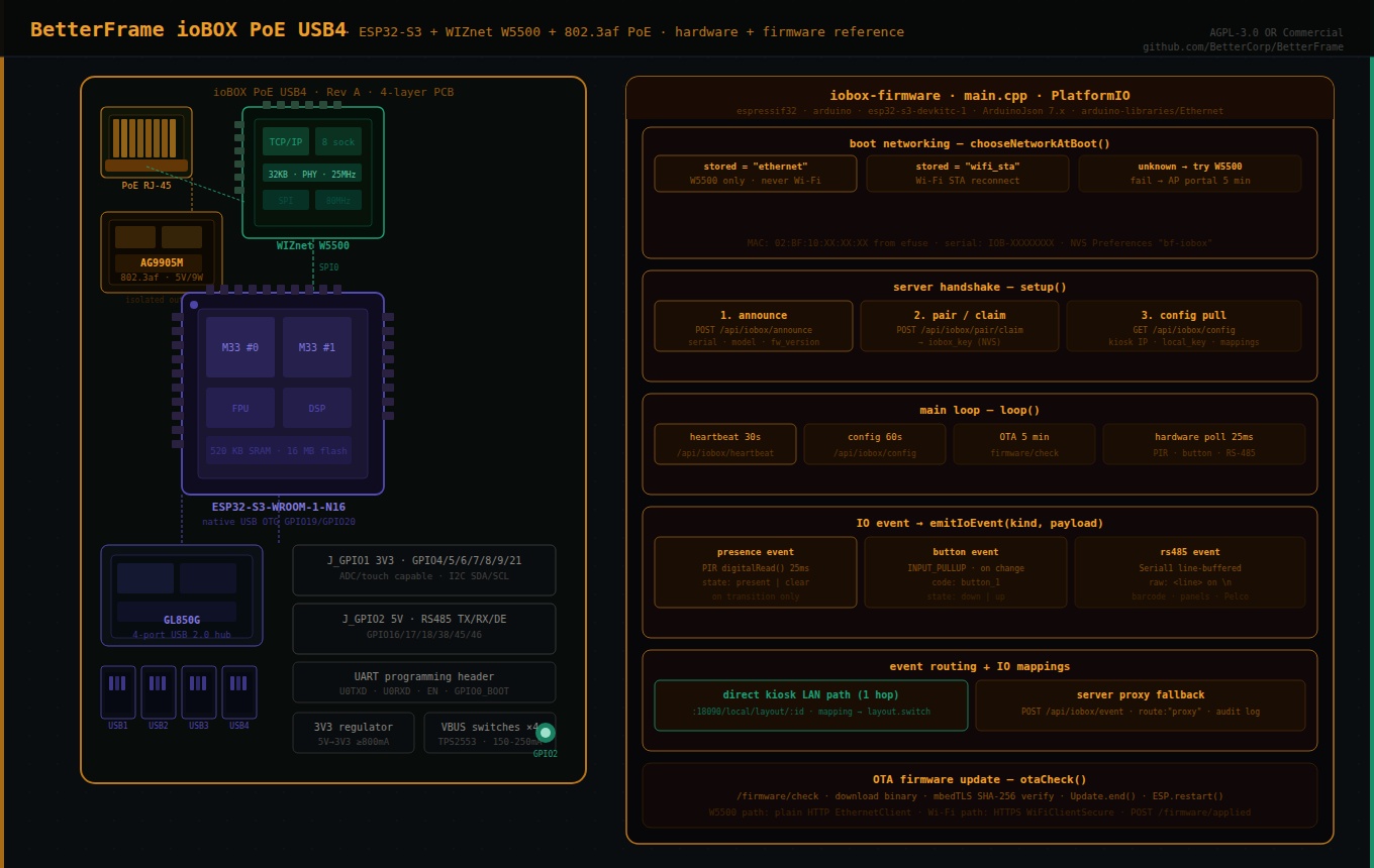
Hardware: ioBOX PoE USB4
The reference hardware design (hardware/iobox-poe-usb4/) is a Rev A board built around six functional blocks: MCU, Ethernet, PoE power, USB hub, IO headers, and per-port USB current switches. It is designed for KiCad/Eagle/EasyEDA capture, with a full BOM, netlist, and pin map committed to the repository.
Main ICs
| Ref | Part | Function |
|---|---|---|
| U1 | ESP32-S3-WROOM-1-N16(R8) | MCU — dual-core Xtensa, 16 MB flash, native USB OTG |
| U2 | GL850G-HHY22 | 4-port USB 2.0 hub downstream |
| U3 | WIZnet W5500 | SPI hardwired TCP/IP Ethernet controller |
| U4 | Silvertel AG9905M / AG9905-MTB | 802.3af PoE PD — isolated 5 V / 9 W output |
| U5 | Buck or high-current LDO | 5 V → 3.3 V, ≥800 mA |
| U6–U9 | TPS2553 / AP22802 class | Per-port USB VBUS current switches (×4) |
| U10–U14 | USBLC6-2SC6 class | USB ESD protection — one upstream, one per port |
The board is designed for a 4-layer PCB with a solid ground plane and no splits under USB differential pairs.
Power Architecture
Everything runs from a single PoE RJ-45:
RJ-45 PoE input
  → Ethernet magnetics → W5500 SPI Ethernet → ESP32-S3
  → PoE center taps / spare-pair power
      → AG9905M isolated 5 V PD module
          → +5V_SYS
              → U5: 3.3 V regulator → +3V3 (ESP32-S3, W5500)
              → GL850G hub (V5 + V33 per hub reference design)
              → U6–U9: per-port VBUS switches → 4× USB-A ports
The AG9905M is an isolated module, meaning the PoE power domain is electrically separated from the system 5 V rail — important for the Ethernet isolation requirements of 802.3af. The board notes a key power budget constraint: four USB ports at 500 mA each exceed a realistic 802.3af 9 W system budget once the ESP32-S3, W5500, and hub are included. Per-port USB current limits should be set to 150–250 mA for HID use, not full charging levels.
The WIZnet W5500: Why It's Here
The W5500 is WIZnet's hardwired TCP/IP Ethernet controller — the TCP/IP stack, MAC, and 10/100 PHY are all implemented in hardware silicon, not firmware. The ESP32-S3 communicates with it purely over SPI and issues socket-level commands; it never touches Ethernet framing, ARP, DHCP, or TCP state machines directly.
For the ioBOX specifically, this matters for three reasons.
PoE power budget. The W5500 consumes around 130 mW active — a small fraction of the 802.3af 9 W envelope. A module with a software TCP/IP stack running on the MCU would burn more cycles and more power. The W5500's hardware offload keeps the ESP32-S3 free for USB HID enumeration, RS-485 parsing, JSON serialization, and OTA management without adding power pressure on an already tight budget.
Predictable boot-time Ethernet. The ioBOX's boot networking rule is strict: if the stored mode is ethernet, the firmware attempts Ethernet only. If the link disconnects after boot, it retries Ethernet indefinitely. It never falls back to Wi-Fi mid-session. For a physical IO controller in a commercial display installation, this predictability is the point — you don't want the device silently switching to Wi-Fi and becoming invisible to the LAN-based kiosk discovery mechanism.
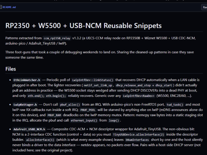
TLS tradeoff acknowledged. The standard Arduino W5500 Ethernet library (arduino-libraries/Ethernet) does not provide TLS. The firmware README documents this explicitly: the iobox_eth variant uses plain HTTP against the BetterFrame server, and the deployment recommendation is to either put the ioBOX on a trusted internal network or terminate TLS upstream (Angie proxy is already in the stack). The iobox_wifi variant uses WiFiClientSecure with mbedTLS for HTTPS. This is an honest engineering tradeoff, not an oversight.
W5500 Pin Map
The SPI connection between ESP32-S3 and W5500 is locked between the hardware design and the platformio.ini build flags — the same GPIO numbers appear in both:
| ESP32-S3 GPIO | Net | W5500 signal |
|---|---|---|
| GPIO10 | ETH_CS | SCSn (chip select) |
| GPIO11 | SPI_MOSI | MOSI |
| GPIO12 | SPI_SCK | SCLK |
| GPIO13 | SPI_MISO | MISO |
| GPIO14 | ETH_INT | INTn (interrupt) |
| GPIO15 | ETH_RST | RSTn (reset) |
Hardware notes from the design: the W5500 uses a 25 MHz crystal with datasheet load capacitors, a 10 kΩ pull-up on reset, and optional 0Ω series links on SPI lines for bring-up. It should be placed close to the RJ-45 magjack with Ethernet differential pairs (ETH_TXP/TXN, ETH_RXP/RXN) kept short and length-matched. The W5500-to-magjack data routing must stay away from the ESP32-S3 antenna keepout area.
USB Host Path
The ESP32-S3 native USB OTG (GPIO19=D−, GPIO20=D+) connects to the GL850G hub upstream port. Four downstream ports feed individual USB-A connectors through USBLC6-2SC6 ESD devices and TPS2553-class VBUS current switches. GPIO19 and GPIO20 are dedicated to USB host and are explicitly excluded from the GPIO expansion headers. The GL850G is strapped for self-powered operation and uses a 12 MHz crystal.
GPIO and RS-485 Headers
Two 2×5 2.54 mm headers expose the remaining GPIOs:
J_GPIO1 — 3.3 V GPIO: GPIO4/5 (ADC/touch capable), GPIO6/7/8/9/21 (general purpose).
J_GPIO2 — Power/serial: 5 V system rail (fused/limited), GPIO16 (RS-485 DE / spare), GPIO17 (RS-485 TX / UART TX), GPIO18 (RS-485 RX / UART RX), GPIO38, GPIO45/46 (strap-sensitive, use carefully), GPIO47/48 (I2C SDA/SCL with optional pull-ups).
A UART programming header (U0TXD, U0RXD, EN, GPIO0) handles flashing, since GPIO19/20 are consumed by USB host and cannot be used for the native USB programming path on Rev A.
Firmware Deep-Dive
The firmware is a single C++ source file (iobox-firmware/src/main.cpp) built with PlatformIO for the espressif32 platform and arduino framework, targeting esp32-s3-devkitc-1. Dependencies are minimal: bblanchon/ArduinoJson@^7.4.2 and arduino-libraries/Ethernet@^2.0.2.
Boot Networking
chooseNetworkAtBoot() runs once in setup() and determines the network mode for the entire session:
stored mode = "ethernet"  → call beginEthernet(); done
stored mode = "wifi_sta"  → call beginWifiSta(); done
no stored mode, eth build → try beginEthernet()
  success → storeMode("ethernet"); done
  fail    → startProvisioningPortal() for 5 minutes
              success → storeMode("wifi_sta"); restart
beginEthernet() calls SPI.begin() on the four SPI pins, Ethernet.init(ETH_CS_PIN), derives a locally administered MAC from the ESP32 efuse MAC (02:BF:10:XX:XX:XX using the low three bytes of the chip MAC), calls Ethernet.begin(mac), then polls for linkStatus() == LinkON and a non-zero DHCP-assigned IP for up to 12 seconds before returning success or failure.
Changing network mode requires a factory reset — the mode is stored in NVS (Preferences, namespace bf-iobox) and only written by explicit provisioning or auto-detection.
Server Handshake: Announce → Pair → Config
Once networkUp is true, setup() runs a three-step server handshake:
1. Announce — POST /api/iobox/announce (unauthenticated) with:
{ "serial": "IOB-XXXXXXXX", "model_hint": "ioBOX-ETHERNET", "firmware_version": "0.1.0", "firmware_arch": "esp32s3", "network_mode": "ethernet" }The serial is derived from the ESP32 efuse MAC as IOB-<4 high hex><8 low hex>. If the server returns "status": "unknown_serial", the device isn't registered yet and the handshake stops.
2. Pair/claim — if no iobox_key is stored in NVS, POST /api/iobox/pair/claim. The server returns an iobox_id and iobox_key, which are persisted to NVS. All subsequent requests carry Authorization: Bearer <iobox_key>.
3. Config pull — GET /api/iobox/config, which returns:
assigned_display.id— which display this ioBOX serveslocal_target.candidates[]— list of{ip, port}for direct kiosk LAN accesslocal_target.local_key— bearer token for the kiosk's local APImappings[]— IO event → action rules (e.g.presenceevent →layout.switch)
Main Loop
loop() runs four periodic tasks after a successful handshake:
| Task | Interval | Function |
|---|---|---|
| Heartbeat | 30 s | POST /api/iobox/heartbeat with IP and firmware version |
| Config refresh | 60 s | Re-pull config and re-check local kiosk reachability |
| OTA check | 5 min | GET /api/iobox/firmware/check, download + apply if newer |
| Hardware poll | 25 ms | Read PIR, button, RS-485 UART; emit events on changes |
The network connection is maintained in maintainSelectedNetwork() every iteration — WiFi.reconnect() for the Wi-Fi path, Ethernet.maintain() for DHCP lease renewal on the W5500 path.
Direct Kiosk Path — The Fast Lane
The most important runtime behavior is the direct kiosk local path. After config pull, the firmware probes the first candidate kiosk IP:
GET http://<kiosk_ip>:18090/local/iobox/check?key=<local_key>If this returns 2xx, localKioskReachable = true. From that point on, every IO event goes directly to the kiosk over LAN first:
POST http://<kiosk_ip>:18090/local/iobox/event?key=<local_key>For layout.switch mappings specifically, the firmware calls the kiosk layout API directly:
GET http://<kiosk_ip>:18090/local/layout/<layout_id>?key=<local_key>This is one LAN hop. A PIR sensor triggering a layout switch does not round-trip through the BetterFrame server at all — it goes ioBOX → kiosk at LAN speed. The event is also forwarded to the server with "route": "direct" for audit logging. If the kiosk is unreachable, the event falls back to POST /api/iobox/event on the server with "route": "proxy".
IO Event Schema
All hardware inputs funnel through emitIoEvent(kind, payload), which constructs a consistent event document:
{ "event_id": "IOB-XXXXXXXX-42", "kind": "presence", "display_id": "...", "occurred_at_ms": 183420, "payload": { "state": "present" }, "local_handled": true, "route": "direct" }The three currently implemented input types:
PIR sensor (BF_PIR_PIN ≥ 0) — polls digitalRead() every 25 ms, emits presence with state: "present" or state: "clear" on transitions. Ignores the first read (state initializes to −1) to avoid spurious boot events.
Button (BF_BUTTON_PIN ≥ 0, INPUT_PULLUP) — emits button with code: "button_1" and state: "down" or state: "up" on transitions.
RS-485 UART (BF_RS485_RX_PIN and BF_RS485_TX_PIN both ≥ 0) — line-buffers Serial1 at 9600 baud, emits rs485 with raw and code set to the trimmed line on each newline. RS-485 DE pin (BF_RS485_DE_PIN) is driven LOW at boot for receive-only default. Buffer caps at 180 characters before reset.
The firmware source explicitly marks USB HID host and binary Pelco PTZ decoding as the next addition points — inside pollHardware() without changing the server API contract.
IO Mappings
The config pull includes a mappings[] array. Each mapping has:
source_kind— the event kind to match (e.g."presence")match_json— key/value pairs to match against the event or its payloadaction— what to do (currently:"layout.switch")params_json— action parameters (e.g.{"layout_id": "abc123"})enabled— boolean guard
runLocalMappings() iterates all enabled mappings against each event, calls runLocalMapping() for each match, and returns whether any local action was executed. The matching is simple JSON-value equality, serialized to string for comparison — no regex, no scripting, intentionally minimal.
OTA Updates
The OTA flow:
- GET
/api/iobox/firmware/check?current=0.1.0&arch=esp32s3&model_id=<model_id> - If
up_to_date: true, return. Otherwise readdownload_url,version,sha256. - Download the binary via
EthernetClient(W5500 path, plain HTTP) orHTTPClient(Wi-Fi path, HTTP or HTTPS). - Stream into
streamUpdateWithSha(): pipes bytes throughmbedtls_sha256_contextwhile writing toUpdate. Verifies SHA-256 digest before callingUpdate.end(). - POST
/api/iobox/firmware/appliedwith version and any error string. ESP.restart()on success.
The SHA-256 verification before Update.end() means a corrupted download aborts cleanly rather than flashing a bad image. Content-Length is used for known-size downloads; the code falls back to UPDATE_SIZE_UNKNOWN when the header is absent.
How It All Connects: ioBOX in the BetterFrame Stack
[PIR / button / RS-485 / USB HID]
        ↓ GPIO / UART / USB
  [ioBOX: ESP32-S3 + W5500]
        ↓ LAN (direct, 1 hop)         ↓ WAN/LAN (via server)
  [Kiosk: Pi 5 Rust app]        [BetterFrame server: Node.js/BSB]
        ↓ GStreamer                    ↓ Node-RED
  [Display: HDMI]               [Automation / webhooks / dashboards]
The ioBOX talks to the kiosk directly for latency-sensitive actions (layout switches, presence-triggered content changes) and to the server for everything that needs persistence, audit, or cross-device coordination. The server never touches RTSP. The kiosk never touches the database. The ioBOX never opens an RTSP connection. Each layer does exactly one job.
What Developers Can Take From This
ESP32-S3 + W5500 as a PoE IO node pattern. The combination of ESP32-S3 native USB host, W5500 hardwired Ethernet, and a PoE PD module on a single board is directly reusable for any application that needs wired-network-connected physical IO with USB HID input — industrial panels, kiosks, interactive installations, access control. The firmware architecture (boot mode selection, NVS persistence, server handshake, direct LAN path) is clean enough to extract and adapt.
Single-cable PoE deployment. Mounting an IO box near a display and running a single Ethernet cable back to a PoE switch is significantly simpler than running separate power and data lines, particularly in ceiling or wall-mount scenarios. The AG9905M isolated module handles the PoE PD compliance; the rest of the board just sees 5 V.
Direct device-to-device LAN path. The pattern of pulling a local device IP and key from a central config server, then talking directly to that device for latency-sensitive operations, is broadly useful. It avoids the server becoming a bottleneck for real-time events while still keeping a single source of truth for configuration and audit logs.
IO event schema as a stable API surface. The emitIoEvent() structure — event ID, kind, display ID, timestamp, payload, route — is designed so that new hardware inputs (USB HID, Pelco PTZ, I2C expanders) can be added without changing how the server or kiosk consumes events. The schema is the contract; the hardware polling is the implementation.
Explicit TLS tradeoffs for embedded Ethernet. The firmware README's honest acknowledgment that W5500 plain HTTP requires a trusted network or upstream TLS termination is the kind of documentation that saves developers from deploying insecurely "for now." The dual-path architecture (TLS on Wi-Fi, plain HTTP on W5500 + proxy termination) is a reasonable model for mixed-trust deployments.
Getting Started
Clone the repository and build the ioBOX firmware:
git clone https://github.com/BetterCorp/BetterFrame
cd BetterFrame/iobox-firmware
 # Wi-Fi variant pio run -e iobox_wifi
 # Ethernet variant (W5500) pio run -e iobox_eth
Override deployment values with PlatformIO build flags or a local_overrides.ini:
[env:iobox_eth] build_flags =   ${env.build_flags}
  -D BF_ETHERNET_VARIANT=1   -D BF_DEFAULT_SERVER_URL=\"https://betterframe.yourdomain.com\"   -D BF_MODEL_HINT=\"ioBOX-ETHERNET\"   -D BF_ETH_CS_PIN=10   -D BF_ETH_SPI_SCK_PIN=12   -D BF_ETH_SPI_MISO_PIN=13   -D BF_ETH_SPI_MOSI_PIN=11   -D BF_PIR_PIN=5   -D BF_RS485_RX_PIN=18   -D BF_RS485_TX_PIN=17   -D BF_RS485_DE_PIN=16
For the full BetterFrame server stack:
cd BetterFrame
npm install # edit sec-config.yaml npm run dev   # in server/
Or via Docker Compose:
docker compose -f docker-compose.coolify.yml up