How to Add Wired Telemetry and Vehicle I/O Control with W5500 on STM32 Nucleo F446RE?
This project is a hardware design for an autonomous wheeled vehicle main control board built around the STM32 Nucleo F446RE.
Summary
This project is a hardware design for an autonomous wheeled vehicle main control board built around the STM32 Nucleo F446RE. The board combines motor PWM outputs, relay switching, RS-485 communication, RGB status indication, and a WIZnet W5500 Ethernet interface. In this architecture, the W5500 is the wired TCP/IP communication block that lets the STM32-based vehicle controller exchange telemetry, commands, and diagnostic data with a control PC, onboard computer, or networked test system.
What the Project Does
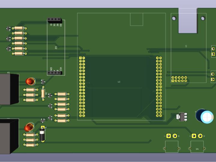
The project is not a full autonomous driving system. It is the main hardware interface board that sits between an STM32 Nucleo F446RE and the electrical subsystems of a small autonomous vehicle.
The board provides four PWM output ports for motor speed control, two relay channels for 12 V actuator or safety switching, a MAX485 transceiver for RS-485 communication, two digital I/O ports, and an RGB LED for local status indication. Power enters through XT30 connectors, and the PCB is designed in KiCad with mounting holes for chassis installation. The repository describes the board as the central hub that interfaces the STM32 with “motor PWM outputs, relay-controlled actuators, RS-485 temperature sensing, W5500 Ethernet connectivity, and an RGB error-status LED.”
The control flow is split into two layers. The STM32 handles local vehicle signals such as PWM, relay GPIO, RS-485 direction control, and status LED outputs. Ethernet provides a higher-level communication path for telemetry, command input, and testing.
A practical system around this board would look like this:
Control PC / onboard computer
│
Ethernet
│
W5500
│ SPI
STM32 Nucleo F446RE
│
┌──────┼────────┬──────────┬──────────┐
PWM Relays RS-485 Digital I/O RGB LED
motors loads sensors peripherals statusWhere WIZnet Fits
The WIZnet product used in this design is the W5500. The project BOM lists it as U1 Ethernet Controller W5500 SPI hardwired TCP/IP Ethernet, and the feature list describes it as the Ethernet controller for remote telemetry and control over TCP/IP.
The W5500 connects to the STM32 through SPI. The repository maps the Ethernet SPI nets to STM32 pins: MOSI on PA7, MISO on PA6, SCK on PA5, and chip select on PA4. On the network side, the W5500 provides the wired Ethernet interface used for TCP/IP communication.
This matters because the STM32F446RE is already responsible for time-sensitive hardware control. Running a full software Ethernet stack on the MCU would add firmware complexity and memory pressure. The W5500 reduces that burden by providing a hardware TCP/IP engine with SPI access, 10/100 Ethernet MAC/PHY, 32 KB internal packet buffer, and support for 8 independent sockets.
In this board, Ethernet is not used to directly drive the motors. It is the supervisory link. It is useful for sending vehicle state to a host, receiving remote commands, debugging during bring-up, and integrating the controller with another onboard computer.
Implementation Notes
The public repository is primarily a hardware design package. The visible files include Gerber, schematic, BOM, images, and README documentation. Although the README describes a firmware stack, the visible GitHub file listing does not expose an inspectable firmware implementation, so socket initialization, packet formats, DHCP/static IP handling, and control logic cannot be verified from source code.
Two hardware details are important for firmware planning.
First, the README states that the board uses a “W5500 Ethernet controller for remote telemetry and control over TCP/IP.” This defines the W5500’s role as a network interface, not a motor-control output.
Second, the signal map assigns the W5500 SPI bus to STM32 pins PA7, PA6, PA5, and PA4. Firmware for this board would need to configure that SPI peripheral and then use a W5500 socket driver or WIZnet ioLibrary-style interface to open TCP or UDP channels.
A sensible firmware split would keep PWM generation, relay fail-safe states, and RS-485 timing local to the STM32, while Ethernet handles non-real-time supervision such as telemetry packets, command messages, configuration, and diagnostics.
Practical Tips / Pitfalls
- Verify XT30 polarity before power-up. The project specifically warns that reverse polarity can damage the AMS1117 and MCU.
- Keep W5500 SPI wiring and firmware configuration consistent with the documented PA7, PA6, PA5, and PA4 mapping.
- Use Ethernet for telemetry and command supervision, not for the inner motor-control loop.
- Decide early whether the vehicle board will use DHCP or a fixed IP address. Static IP is usually easier for bench testing.
- Check RJ45 link status before debugging firmware sockets. A link-layer fault can look like a TCP/IP issue.
- Treat relay switching as a noise source. The board includes a 1000 µF bulk capacitor, but actuator wiring and relay coils can still disturb logic rails.
- Confirm MAX485 transmit/receive direction control before connecting multiple RS-485 devices to the bus.
FAQ
Why use W5500 in this STM32 vehicle control board?
The W5500 gives the STM32 a wired TCP/IP interface without requiring the MCU to run the full Ethernet stack in software. That is useful because the STM32 also has to manage PWM outputs, relay GPIO, RS-485 communication, digital I/O, and status indication.
How does the W5500 connect to the STM32 Nucleo F446RE?
It connects over 3.3 V SPI. The documented net map assigns MOSI to PA7, MISO to PA6, SCK to PA5, and chip select to PA4. Firmware would configure the STM32 SPI peripheral on those pins and communicate with the W5500 through register and socket operations.
What role does W5500 play in this project?
It provides the board’s Ethernet path for telemetry, remote command input, diagnostics, and system integration. The vehicle-facing outputs remain PWM, relays, RS-485, and GPIO; the W5500 is the network bridge into that controller.
Can beginners follow this project?
Beginners can study the board architecture, but building it requires comfort with PCB assembly, STM32 pin mapping, 12 V power distribution, relay loads, RS-485 wiring, and Ethernet bring-up. It is better treated as a hardware reference than a complete beginner tutorial.
How is W5500 Ethernet different from using Wi-Fi here?
Wired Ethernet avoids Wi-Fi pairing, RF interference, and variable wireless latency during development and testing. The trade-off is cabling. For a moving vehicle, Ethernet is best used for bench testing, tethered debugging, or connection to an onboard computer or network switch.