WIZnet Interior Sensor Board
WIZnet Interior Sensor Board
0
Components
Hardware components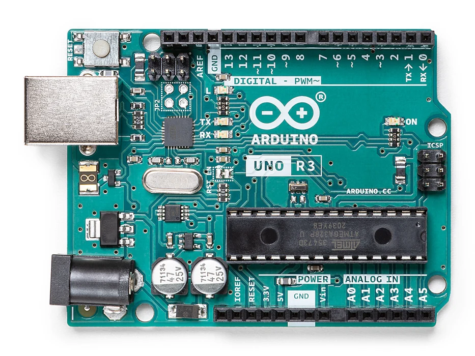
Arduino - Arduino UNO
x 1

WIZnet WIZ750SR
x 1
Soldering iron (generic)
x 1
Tarantula
x 1
arduino.cc
x 1
nodered.org
x 1
PCBway.com
x 1
thingspeak.com
x 1
WIZnet-S2E-Tool
x 1
Project description
ABOUT THIS PROJECT
Here is a simple setup for monitoring inputs from an Arduino to the cloud using a WIZnet Serial to Ethernet adapter and Node-RED to split the messages up and sending it to?ThingSpeak?where it can be monitored and controlled from anywhere in the world.
By using this device, I discovered yet another way to send data without MQTT which is really interesting... You can use just about any Arduino/ESP device to send data to the cloud using the WIZnet as long as it has a TX/RX port. The WIZnet device can be used for setting up and Arduino based home automation system without the use of wireless devices and complicated code... If you have a?serial.Write?in the Code you can send it via Ethernet..
There are five components to this project:
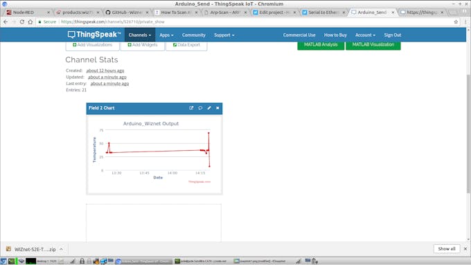
 ThingSpeak.com?Output
 Tip #1: When soldering the SMD parts...?Solder?your?SMD?parts?first
* when using solder as opposed to solder paste solder 1 pad place your part heat the solder and let cool before moving your tweezers
* when cooled solder the other side optimum temp for this process is 300 degrees
Tip#2: Buy some low temp solder paste for the power chip and deposit 2 thin lines across the pads. *See pictures put the Board in a small oven at 350 degrees until you see the paste turn to solder... Remove and check board before it cools.?Keep an eye on the process!
Tip #1: When soldering the SMD parts...?Solder?your?SMD?parts?first
* when using solder as opposed to solder paste solder 1 pad place your part heat the solder and let cool before moving your tweezers
* when cooled solder the other side optimum temp for this process is 300 degrees
Tip#2: Buy some low temp solder paste for the power chip and deposit 2 thin lines across the pads. *See pictures put the Board in a small oven at 350 degrees until you see the paste turn to solder... Remove and check board before it cools.?Keep an eye on the process!
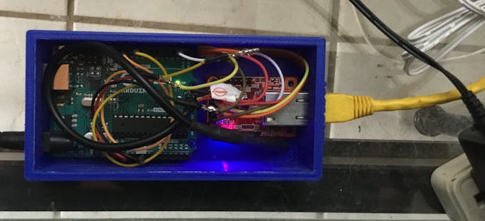
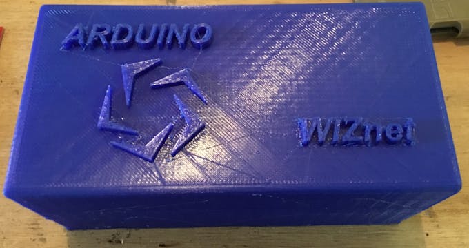
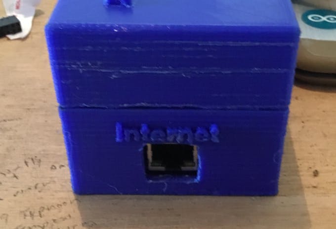
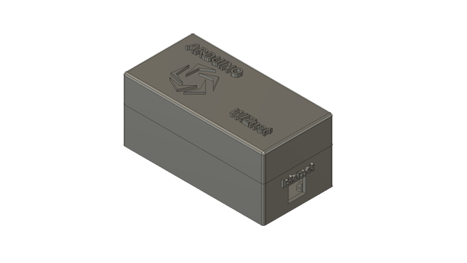 I?made?the?box?fairly?tall?to?accommodate?more?wiring?and?sensors?in?the?future...
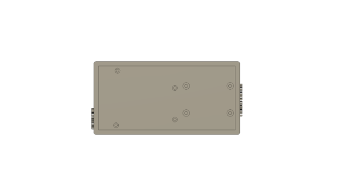 I am attaching a Slicer file opened with [UltiMaker Cura]
- Setting up the WIZnet device
- Arduino voltage/current/temperature/accelerometer board design and soldering
- Arduino hookups
- Node-RED setup
- 3D-printed box for the devices
1. Setting Up the WIZnet Device
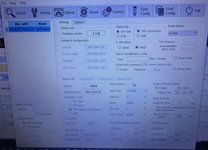
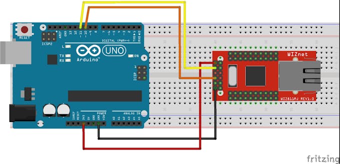
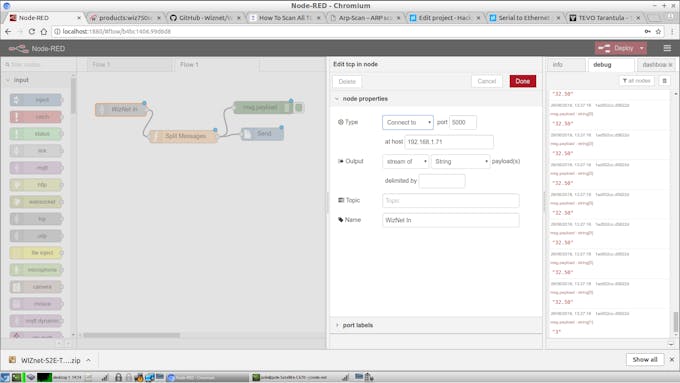
First power up the WIZnet using 3.3V DC and Ground to the pins shown below. Plug in an Ethernet cable preferably Cat5e or Cat6. Look for lights then go to your computer and do the following: I used the WIZnet SE2 configuration Program and set the Ip allocation to DHCP then pressed “Setting“ I did another search and it came up a the Following IP address?192.168.1.71 Next was the Serial setup. I used "TCP Mixed." Local port 5000 and the remote IP is The IP of the WIZnet device. I don't have a screen shot Program installed so I have to rely on Pictures for this Part from my PC.
ThingSpeak.com?Output
2. Arduino Power Shield and Wiring Hookups
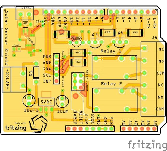
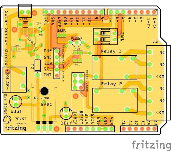
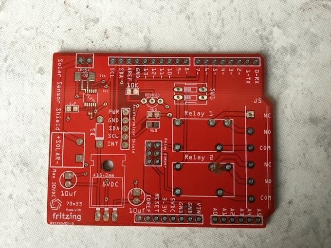
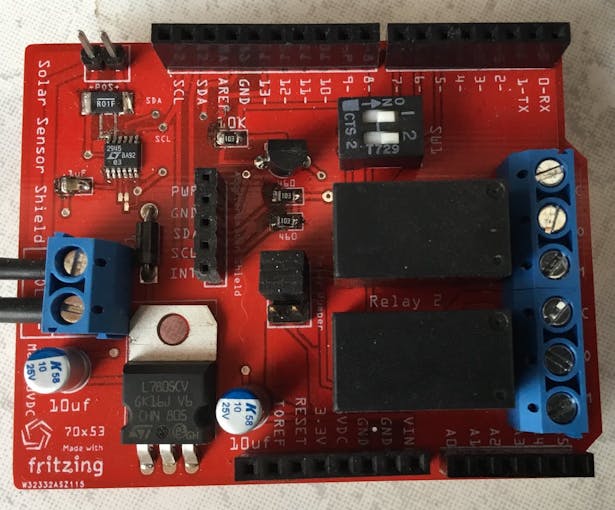
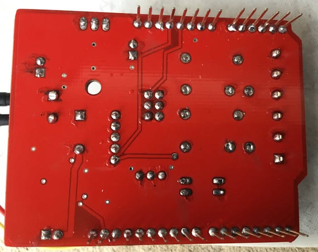
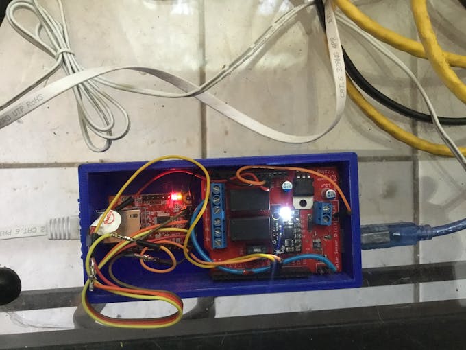
I soldered the female and male pins together and intend to tape the connections up to prevent short circuits. The Power Shield Board is my brainchild and am very proud of it..It is capable of providing power to the ARDUINO and the WIZnet all the while sending data ..There is an on board DS18B20 temperature sensor as well as an I2C Accelerometer. sending XYZ co-ordinates and 2 Controllable Relays .. The images below are of the Arduino shield. The first image is of the original one that is shown in the photos. The second one is a revamped design. I've added a higher amperage and higher voltage regulator. The first voltage regulator is good for 300mA maximum 18 volts DC and the second is good for 1.5 Amps and 30VDC which is more in line with powering off of a larger 24 volt solar array. I also moved the screw connectors forward and gave myself more space as it was tight fitting the relay screw connectors into their place. I also thickened up the relay PCB connections to take up to 5 amps comfortably.
Tip #1: When soldering the SMD parts...?Solder?your?SMD?parts?first
* when using solder as opposed to solder paste solder 1 pad place your part heat the solder and let cool before moving your tweezers
* when cooled solder the other side optimum temp for this process is 300 degrees
Tip#2: Buy some low temp solder paste for the power chip and deposit 2 thin lines across the pads. *See pictures put the Board in a small oven at 350 degrees until you see the paste turn to solder... Remove and check board before it cools.?Keep an eye on the process!
Simple Wiring
- Red +3.3 VDC
- Black GND
- Yellow RX-TX
- Orange TX-RX
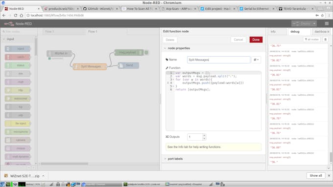
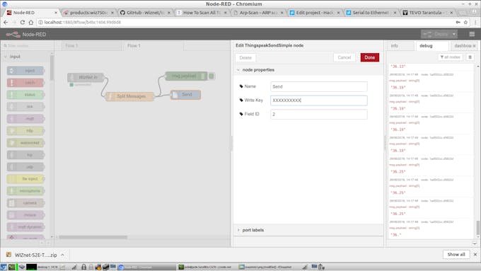
3. Node-Red
4. 3D Printing Your Enclosure
I?made?the?box?fairly?tall?to?accommodate?more?wiring?and?sensors?in?the?future...
I am attaching a Slicer file opened with [UltiMaker Cura]
Simple TX RX Code with DS181 TEmperature SensorClojure
/*
  Software serial multple serial test

 Receives from the hardware serial, sends to software serial.
 Receives from software serial, sends to hardware serial.

 The circuit:
 * RX is digital pin 10 (connect to TX of other device)
 * TX is digital pin 11 (connect to RX of other device)

 Note:
 Not all pins on the Mega and Mega 2560 support change interrupts,
 so only the following can be used for RX:
 10, 11, 12, 13, 50, 51, 52, 53, 62, 63, 64, 65, 66, 67, 68, 69

 Not all pins on the Leonardo and Micro support change interrupts,
 so only the following can be used for RX:
 8, 9, 10, 11, 14 (MISO), 15 (SCK), 16 (MOSI).

 created back in the mists of time
 modified 25 May 2012
 by Tom Igoe
 based on Mikal Hart's example

 This example code is in the public domain.

 */
#include <SoftwareSerial.h>
#include <OneWire.h>
#include <DS18B20.h>
SoftwareSerial mySerial(10, 11); // RX, TX
// 1-Wire devices connected to digital pin 2 on the Arduino.
DS18B20 ds(2);
int temp;
void setup() {
  // Open serial communications and wait for port to open:
  Serial.begin(9600);
  while (!Serial) {
    ; // wait for serial port to connect. Needed for native USB port only
  }

  // Print number of devices on the bus.
  Serial.print("Devices: ");
  Serial.println(ds.getNumberOfDevices());
  Serial.println();
  Serial.println("Goodnight moon!");

  // set the data rate for the SoftwareSerial port
  mySerial.begin(115200);
 // mySerial.println("Hello, world?");
}

void loop() { // run over and over
  if (mySerial.available()) {
    Serial.write(mySerial.read());
  }
  if (Serial.available()) {
    mySerial.write(Serial.read());
  }
     // Iterate through all devices.
  while(ds.selectNext())
  {
    // Print family name.
    switch(ds.getFamilyCode())
    {
      case MODEL_DS18S20:
        Serial.println("Model: DS18S20");
        break;
      case MODEL_DS1820:
        Serial.println("Model: DS1820");
        break;
      case MODEL_DS18B20:
        Serial.println("Model: DS18B20");
        break;
      default:
        Serial.println("Unrecognized Device");
        break;
    }

    // Print address.
    uint8_t address[8];

    ds.getAddress(address);

    Serial.print("Address:");

    for(uint8_t i = 0; i < 8; i++)
    {
      Serial.print(" ");
      Serial.print(address[i]);

    }

    Serial.println();

    // Print resolution.
    Serial.print("Resolution: ");
    Serial.println(ds.getResolution());

    // Print power mode.
    Serial.print("Power Mode: ");

    if(ds.getPowerMode())
    {
      Serial.println("External");
    }
    else
    {
      Serial.println("Parasite");
    }

    // Print temperature in degrees Celcius and degrees Fahrenheit.
    Serial.print("Temperature: ");
    Serial.print(ds.getTempC());
    Serial.print(" C / ");
    Serial.print(ds.getTempF());
    Serial.println(" F");
    mySerial.print(":");
    mySerial.print(ds.getTempC());

    // Print an empty line.
    Serial.println();
  }

  // Wait 10 seconds.
  delay(1000);
}

