
W55RP20 smart doorbell
A smart camera doorbell where W55RP20 controls a vision NPU. It texts user when a stranger is detected.
COMPONENTS
Hardware components


 Software Apps and online services

WIZnet - W55RP20
x 1
Seeedstudio - Grove Vision AI Module
x 1
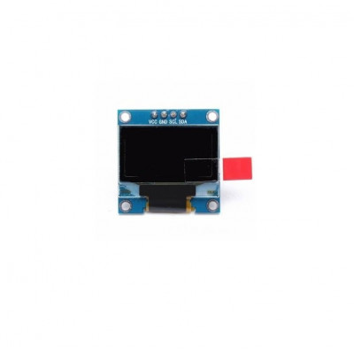
SOLOMON SYSTECH - Monochrome 0.96" 128x64 OLED Graphic Display
x 1
Arduino - Arduino IDE
x 1
PROJECT DESCRIPTION
Steps to run
W55RP20 Smart Doorbell
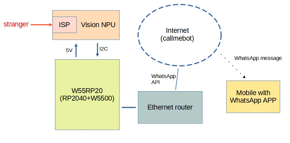
The W55RP20 smart doorbell proof-of-concept integrates the W55RP20-Arduino platform with the Seeed Studio Grove AI Vision V2 module to deliver intelligent tenant recognition and real-time notifications. The Grove AI Vision V2 performs on-device image classification, distinguishing between known tenants and strangers at the door. Once classification is complete, the W55RP20-Arduino acts as the communication gateway, triggering a secure message dispatch. Through its Ethernet interface, the W55RP20 sends a WhatsApp notification directly to the user’s mobile device, ensuring immediate awareness of visitor identity. This modular design demonstrates a scalable approach to combining embedded vision and IoT messaging for smart home security.
System diagram
Hardware
Components
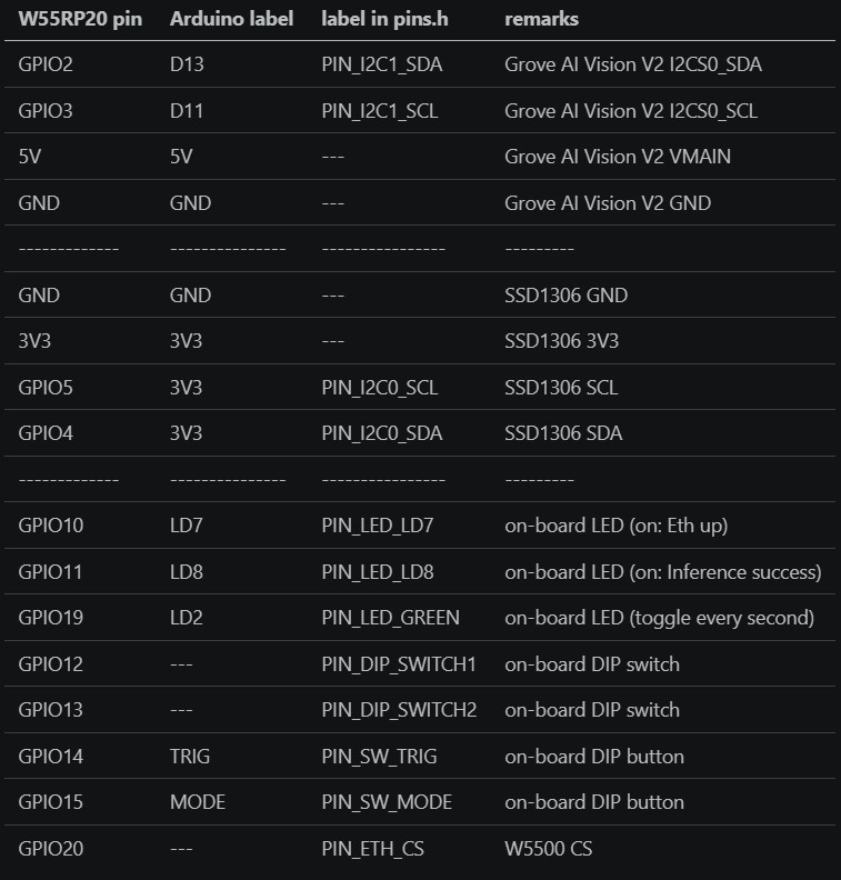
pin assignments
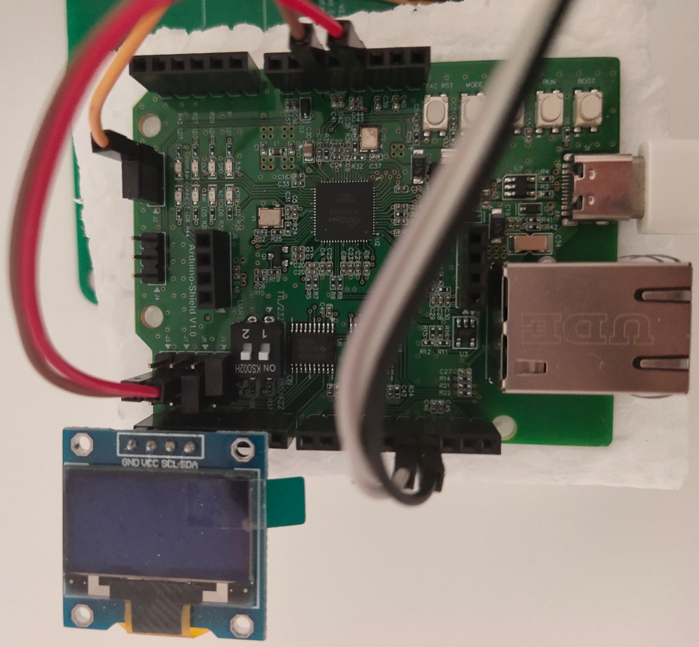
PCBA photo
Prerequisite
1. Follow the instruction on https://sensecraft.seeed.cc/ai/home to install the Pet Detection AI model on the Grove Vision AI Module V2
https://sensecraft.seeed.cc/ai/view-model/60084-pet-detection
note v1.0.3 does NOT work. A pull-request is submitted on 19 Apr 2026.
Please modify Seeed_Arduino_SSCMA.cpp by yourself, before the pull-request is accepted
int SSCMA::invoke(int times, bool filter, bool show)
{
    ...

    snprintf(cmd, sizeof(cmd), CMD_PREFIX "%s=%d,%d,%d" CMD_SUFFIX,
-             CMD_AT_INVOKE, times, !filter, filter); // AT+INVOKE=1,0,1\r\n
+             CMD_AT_INVOKE, times, filter, !show);  // AT+INVOKE=1,0,1\r\n
    write(cmd, strlen(cmd));

    ...
}
note: a cloned Seeed_Arduino_SSCMA is available at https://github.com/teamprof/Seeed_Arduino_SSCMA which will be removed after it accepted the pull-request.
Steps to run
Build firmware
- Follow the instruction on https://www.callmebot.com/blog/free-api-whatsapp-messages/ to get the APIKey
- Clone this github code by "git clone https://github.com/teamprof/w55rp20-smart-doorbell"
- Open the w55rp20-smart-doorbell.ino in Arduino IDE
- Open the secret.h file and replace the placeholder values with your mobile number and the API key provided by CallMeBot
#define MOBILE_NUMBER "<MobileNumber>"
#define APIKEY "<ApiKey>"
- On Arduino IDE, click menu "Tools" -> "Board: " -> "Board Manager..." -> "WIZnet W55RP20-EVB-Pico"
- On Arduino IDE, click menu "Tools" -> "Debug Port" -> "Serial"
- On Arduino IDE, click menu "Tools" -> "CPU Speed" -> "133 MHz"
- On Arduino IDE, click menu "Tools" -> "Operation System" -> "FreeRTOS SMP"
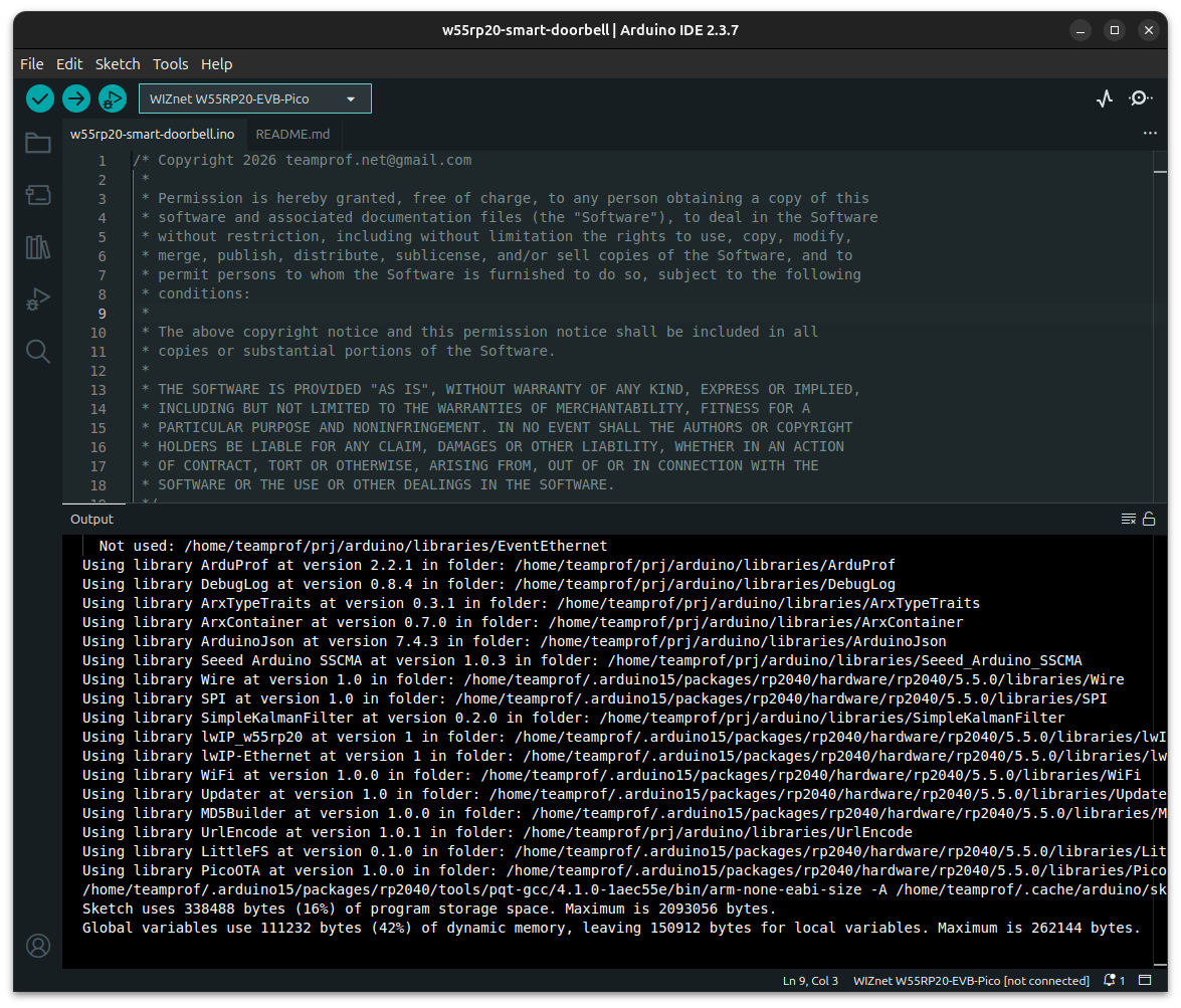
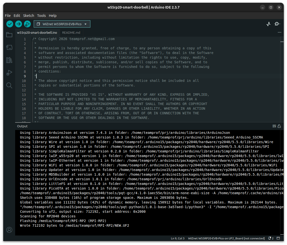
- On Arduino IDE, click menu "Sketch" -> "Verify/Compile"
If everything goes smoothly, you should see the following screen.
Wiring and settings
- wiring "W55RP20-Arduino" - "Grove AI Vision V2" according to the session "pin assignments" above
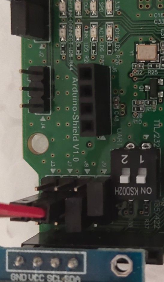
- short "W55RP20-Arduino" J2.1 and J2.2 (IOREF = 3V3)
- open "W55RP20-Arduino" J3
- open "W55RP20-Arduino" J7
- short "W55RP20-Arduino" J8.2 and J8.3 (D2 = GPIO5 = I2C0_SCL)
- short "W55RP20-Arduino" J9.1 and J9.2 (D3 = GPIO4 = I2C0_SDA)
- put DIP switch 1 to ON state (start ThreadEth)
- put DIP switch 2 to ON state (start ThreadAi)
Flash firmware
- Connect W55RP20-Arduino to PC, upload firmware by clicking menu "Sketch" -> "Upload"
If everything goes smoothly, you should see the following screen.
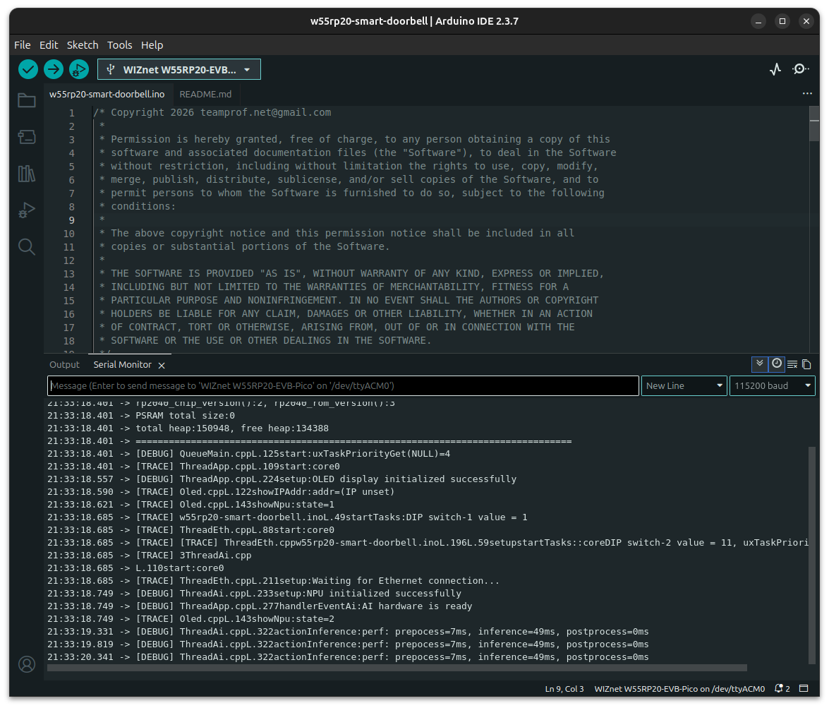
Test firmware
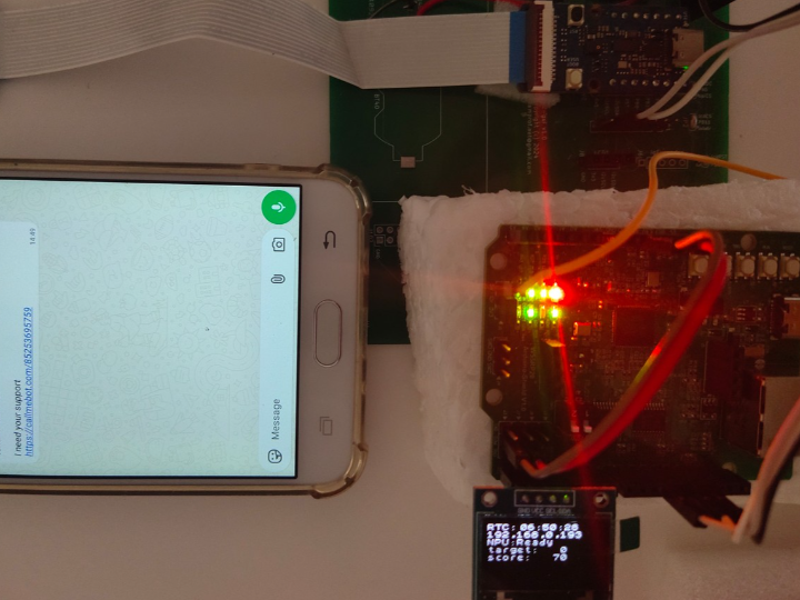
- Launch "Serial Monitor" on Arduino IDE, press "RESET" button on the board, you should see the following screen.
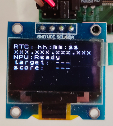
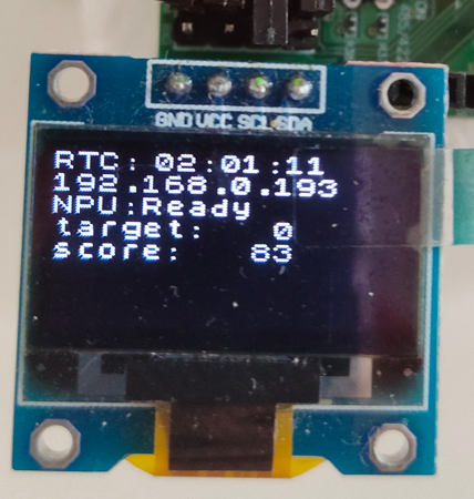
- OLED display as below
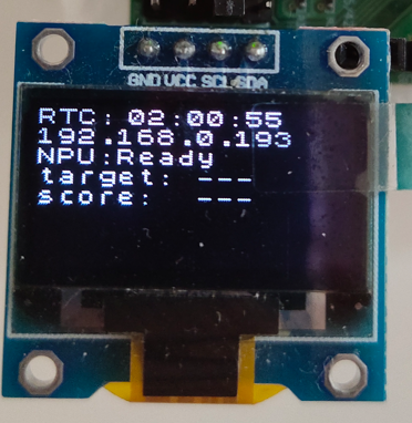
- Connect an Ethernet cable between the board and router, you should see the following OLED display once Etheret is up and NTP is success
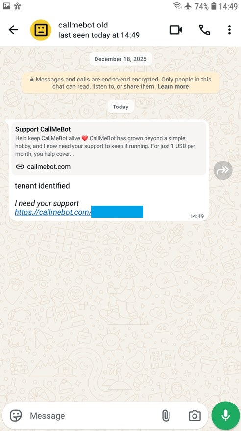
- show a "cat" image in front of the camera. OLED should display as below
an alert message "Tenant identified" should be received on WhatsApp app couple seconds later
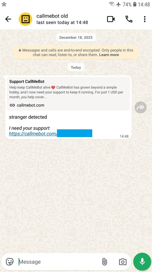
- show a "dog" image in front of the camera. an alert message "Stranger detected" should be received on WhatsApp app
Video demo
Video demo is available on video
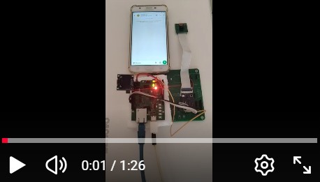
00:01 power up
00:13 put a "cat" image in front of the camera
00:48 WhatsApp received "tenant identified" message
01:04 put a "dog" image in front of the camera
01:22 WhatsApp received "stranger detected" message
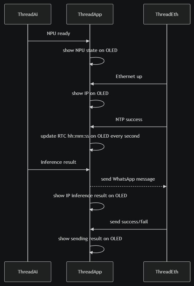
Software flow
License
- The project is licensed under GNU GENERAL PUBLIC LICENSE Version 3
Copyright
- Copyright 2025 teamprof.net@gmail.com. All rights reserved.
Documents
-
w55rp20-smart-doorbell
source code

Comments
Write