Ethernet TCP Performance with Arduino
TCP segments are encapsulated in IP packets, which are in turn encapsulated in Ethernet frames.

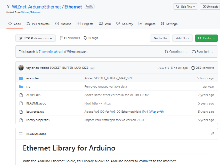
Original : https://github.com/WIZnet-ArduinoEthernet/Ethernet/tree/EXP-Performance
This content was created with the assistance of ChatGPT, an artificial intelligence language model developed by OpenAI.
Ethernet is one of the most widely used networking technologies that provide a means to transmit data packets between devices over a LAN (Local Area Network). An Ethernet frame is the fundamental unit of data that is transmitted over the Ethernet network. The Ethernet frame size has a significant impact on the performance of the network and the behavior of higher-layer protocols such as IP and TCP.
Ethernet Frame Size
The Ethernet frame size is defined by the IEEE 802.3 standard and has a minimum size of 64 bytes and a maximum size of 1518 bytes. The frame consists of the following components:
- Preamble: A sequence of 7 bytes (56 bits) used to synchronize the transmitter and receiver clocks.
- Start Frame Delimiter (SFD): A 1-byte (8-bit) field that marks the beginning of the frame.
- Destination and Source MAC addresses: These are 6-byte (48-bit) fields that identify the destination and source devices.
- EtherType or Length: A 2-byte (16-bit) field that identifies the protocol encapsulated in the frame. If the value of this field is less than or equal to 1500 (0x05DC), it indicates the length of the payload, otherwise, it identifies the protocol type.
- Payload: This is the actual data that is transmitted over the network. It can range from 46 to 1500 bytes.
- Frame Check Sequence (FCS): A 4-byte (32-bit) field used to verify the integrity of the frame.
https://en.wikipedia.org/wiki/Ethernet_frame
IP (Internet Protocol)
The maximum size of an Ethernet frame is 1518 bytes, but the maximum size of an IP packet is 65535 bytes. Therefore, if an IP packet is larger than the maximum size of an Ethernet frame, it needs to be fragmented into smaller packets that can fit into multiple Ethernet frames. This fragmentation process can introduce delays and increase the overall network traffic, which can negatively impact the performance of the network.
In addition, the overhead of the Ethernet header and the IP header reduces the maximum size of the payload that can be transmitted in a single packet. For example, if an IP packet has a payload of 1460 bytes, it needs to be split into two Ethernet frames, each with a payload of 730 bytes, to fit into the maximum size of an Ethernet frame.
WIZnet Chip doesn't support IP fragment.
An IP datagram is a basic unit of data in the Internet Protocol (IP) that carries data packets across an IP network. An IP datagram contains information about the source and destination of the packet, the size of the packet, and the data payload. It is used to transport data between devices on the Internet and other IP networks.
The structure of an IP datagram is defined by the IP protocol specification and consists of several fields, including:
- Version: This field specifies the version of IP that is being used. Currently, the most widely used version is IPv4, but IPv6 is gaining popularity.
- Header Length: This field specifies the length of the IP header in 32-bit words. The minimum length of the IP header is 20 bytes (5 words), and the maximum length is 60 bytes (15 words).
- Type of Service (ToS): This field is used to indicate the priority and the type of data that is being transmitted. It is also used for Quality of Service (QoS) management.
- Total Length: This field specifies the total length of the IP datagram, including the header and the data payload. The minimum length is 20 bytes (header only), and the maximum length is 65535 bytes.
- Identification: This field is used to identify a particular IP datagram and is used for fragmentation and reassembly of IP packets.
- Flags: This field is used to control fragmentation of IP packets.
- Fragment Offset: This field specifies the offset of the current fragment in the original IP packet.
- Time-to-Live (TTL): This field specifies the maximum number of network hops that the IP packet can traverse before being discarded.
- Protocol: This field specifies the type of protocol that is being used for the data payload, such as TCP, UDP, or ICMP.
- Header Checksum: This field is used to verify the integrity of the IP header.
- Source IP Address: This field specifies the IP address of the sender.
- Destination IP Address: This field specifies the IP address of the recipient.
- Options: This field is used to carry additional information that is required for specific applications or protocols.
- Data Payload: This field contains the actual data that is being transmitted.
https://en.wikipedia.org/wiki/Internet_Protocol_version_4
TCP (Transmission Control Protocol)
TCP is a connection-oriented protocol that provides reliable data transmission between devices over a network. TCP segments are encapsulated in IP packets, which are in turn encapsulated in Ethernet frames. The maximum size of a TCP segment is determined by the Maximum Segment Size (MSS), which is negotiated during the TCP three-way handshake.
If the MSS negotiated during the TCP three-way handshake is larger than the maximum size of the payload that can be transmitted in a single Ethernet frame, TCP needs to split the segment into multiple segments, each of which can fit into a single Ethernet frame. This segmentation process can increase the overhead of the TCP header and the IP header, which can negatively impact the performance of the network.
The TCP segment consists of several fields, including:
- Source Port: A 16-bit field that identifies the source port of the application sending the data.
- Destination Port: A 16-bit field that identifies the destination port of the application receiving the data.
- Sequence Number: A 32-bit field that identifies the sequence number of the first data byte in the segment.
- Acknowledgment Number: A 32-bit field that contains the next sequence number the sender of the segment expects to receive.
- Data Offset: A 4-bit field that specifies the length of the TCP header in 32-bit words.
- Reserved: A 6-bit field that is reserved for future use.
- Flags: A 6-bit field that contains control bits used for different purposes, including indicating the start and end of a segment, and indicating if data is urgent or requires acknowledgment.
- Window Size: A 16-bit field that specifies the size of the receive window, which is used for flow control.
- Checksum: A 16-bit field that contains the checksum value for the TCP segment.
- Urgent Pointer: A 16-bit field that points to the last byte of urgent data in the TCP segment.
- Options: A variable-length field that contains optional parameters used to support specific features or functions.
- Data Payload: A variable-length field that contains the actual data being transmitted.
https://en.wikipedia.org/wiki/Transmission_Control_Protocol
TCP segments are used to transmit data between applications running on different hosts in a reliable and ordered manner. The TCP protocol uses a sequence of segments to transmit large amounts of data, with each segment being acknowledged by the receiver before the next segment is sent. This ensures that data is delivered in the correct order and is not lost or corrupted during transmission.
If the MSS negotiated during the TCP three-way handshake is larger than the maximum size of the payload that can be transmitted in a single Ethernet frame, TCP needs to split the segment into multiple segments, each of which can fit into a single Ethernet frame. This segmentation process can increase the overhead of the TCP header and the IP header, which can negatively impact the performance of the network.
So far, we have examined the structure of data that is sequentially transmitted from Ethernet MAC to IP to TCP.
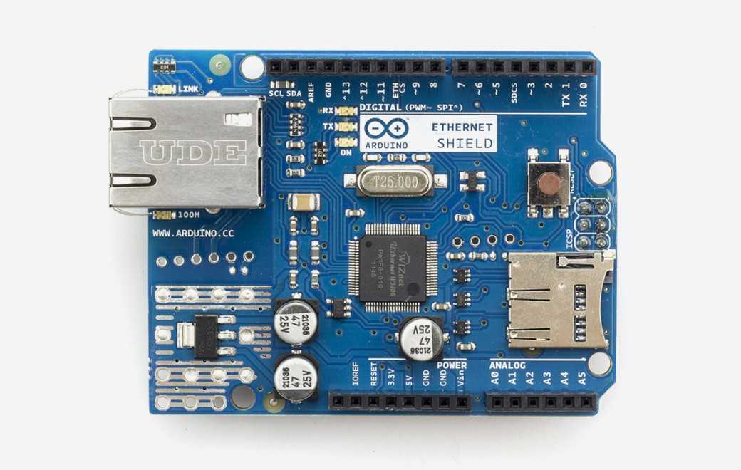
Fortunately, you can use the Ethernet Shield with the WIZnet Chip on Arduino, so even if you do not know about this structure, you can use the Read/Write of the Server or Client and communicate through TCP via a Socket. The maximum size of this Socket varies depending on the Chip, but it is defined as 2KB by default in the Ethernet Library. However, most examples in the Arduino Ethernet Library do not use this Socket buffer well enough. The ChatServer example reads and writes one byte at a time.
To reiterate, the Socket buffer is typically 2KB in size. The existing examples have been modified and distributed on the EXP-Performance branch of the Github WIZnet-ArduinoEthernet/Ethernet repository in order to make use of the Socket buffer.
https://github.com/WIZnet-ArduinoEthernet/Ethernet/tree/EXP-Performance
As shown in the figure below, by using the maximum size of the Ethernet frame for receiving and sending packets, you can send more data at once.
192.168.50.103 : PC
192.168.50.177 : W5100S-EVB-Pico
// 20230320 edited
Even if the socket buffer size is bigger than the Ethernet frame size, the actual packet length is limited by the ethernet frame size.
In the Arduino Ethernet library, the maximum data length is equal to the socket size.
So, if you want to send data bigger than the socket size, you should send data several times per socket size in the Arduino Ethernet library.
Remember one packet's maximum length is not equal to the socket size.
In ChatServer-2048_1024.ino, captured to send data of 3072 bytes.
Thank you for reading.

