
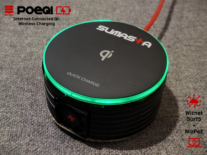
WiZ PoeQi : Internet-connected Wireless Qi Charger
WIZ-enabled gadget using Power over Ethernet (PoE) for internet and power, paired with wireless Qi charging for seamless connectivity.
WIZnet - W7500
x 1
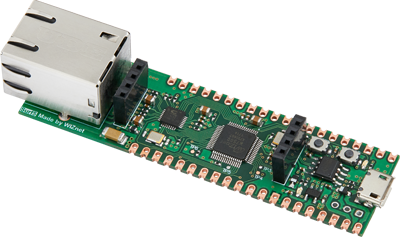
WIZnet - Surf5
x 1
microsoft - VS Code
x 1
Introduction
Hi there! For this year's contest, I've decided to build something that embodies simplicity and practicality while being incredibly useful for everyday life. I wanted to create a device that's not only functional but also stands out as a unique and cool gadget you can't just buy on the market. After much thought, I settled on the idea of PoeQi, an innovative device that combines Power over Ethernet (PoE) for internet connectivity and wireless Qi charging. This gadget reduces the clutter of cables, simplifies your tech setup, and brings a touch of modern convenience to your daily routine. The PoeQi project represents my passion for merging cutting-edge technology with practical applications, making it a one-of-a-kind solution that truly stands out.
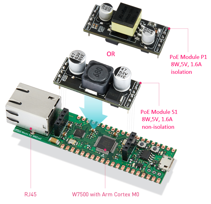
The primary enabler of PoeQi is not just the Surf5 board powered by the W7500 microcontroller, but more importantly, the Wiz-PoE module that provides IEEE802.3af-compliant Power over Ethernet. As per the standard, the Wiz-PoE module can supply up to 8W, which is sufficient for standard wireless Qi charging applications. Additionally, the onboard W7500 processor and its peripherals consume very little power, allowing the majority of the spare power budget to be allocated to wireless charging. This efficient power distribution ensures that PoeQi remains highly functional while keeping the design simple and practical. Pretty neat, right?!
Moreover, the fact that PoE is safe makes it even more interesting. The safety of the Power over Ethernet (PoE) standard, especially the IEEE 802.3af specification, is a key factor in its widespread adoption and reliability. The IEEE 802.3af standard ensures that power delivery over Ethernet cables is both safe and efficient. This standard incorporates various safety mechanisms, including power negotiation, which ensures that devices only receive the amount of power they need, preventing overloading and potential damage. Additionally, it features built-in short-circuit and overload protection, which automatically cuts off power in case of a fault, preventing damage to both the power sourcing equipment (PSE) and the powered device (PD). The use of low-voltage DC power (up to 48V) further reduces the risk of electric shock. These stringent safety protocols make IEEE 802.3af-compliant PoE systems reliable and secure for powering sensitive electronic devices, such as the components in PoeQi.
In Action
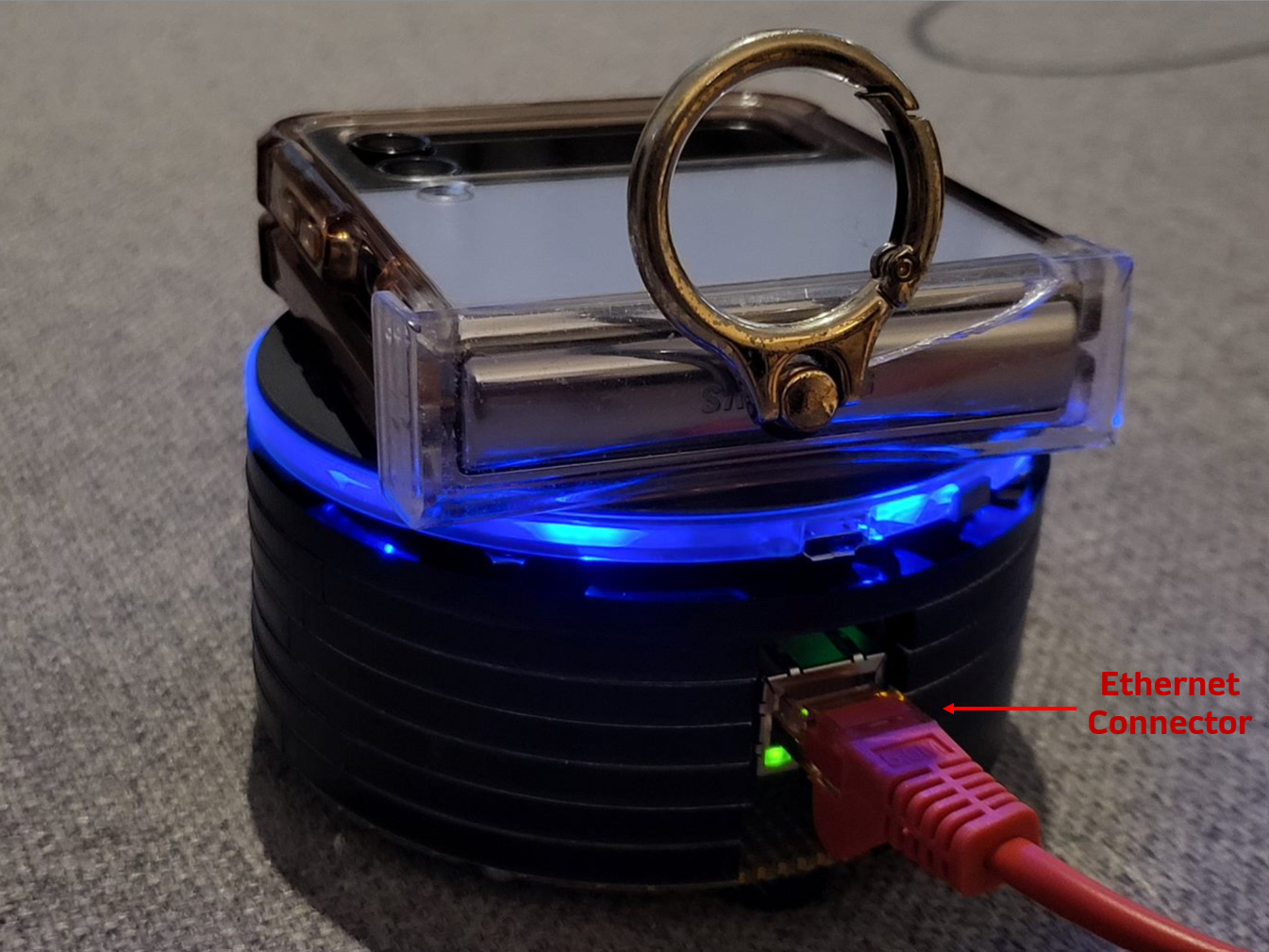
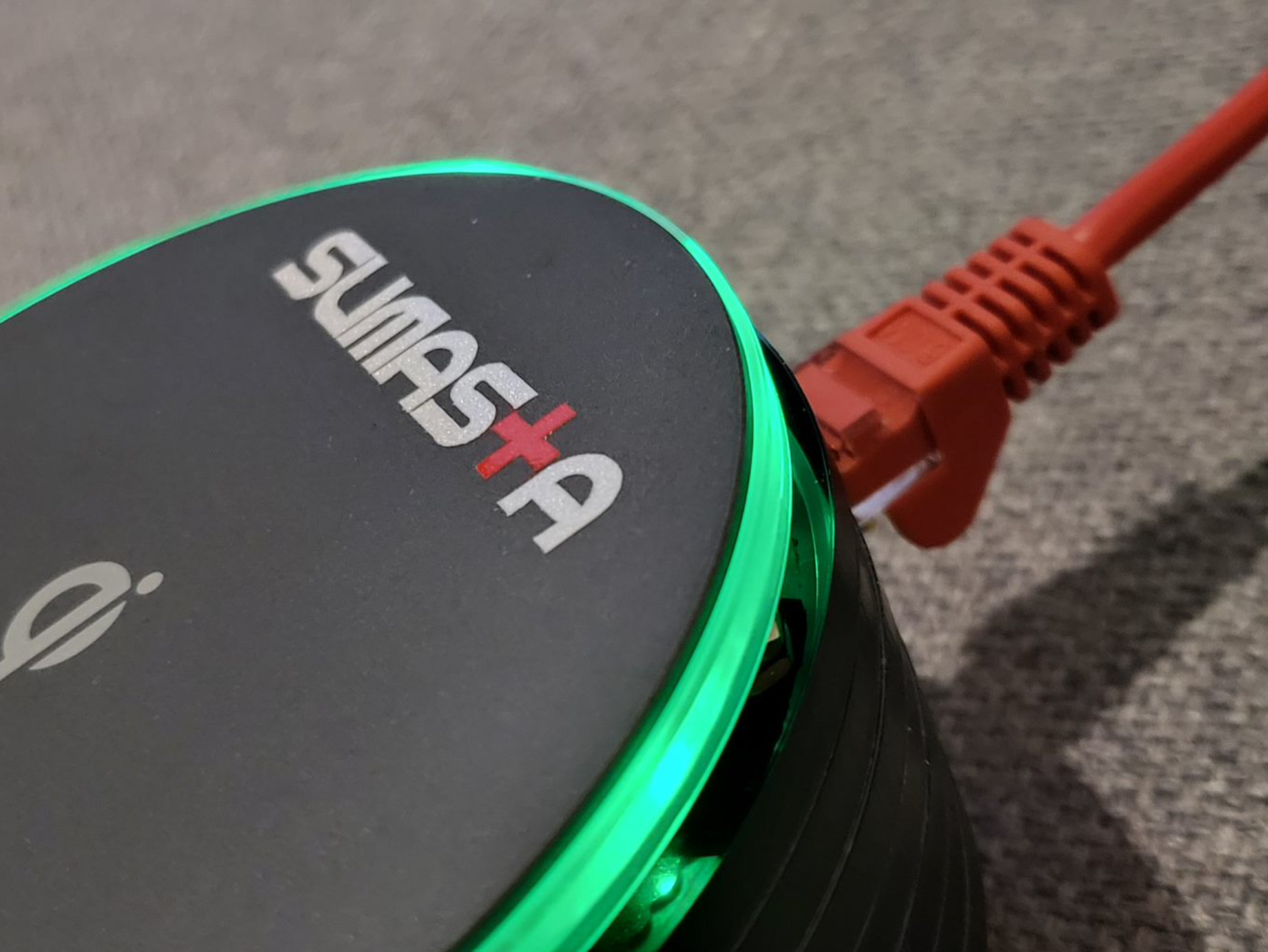
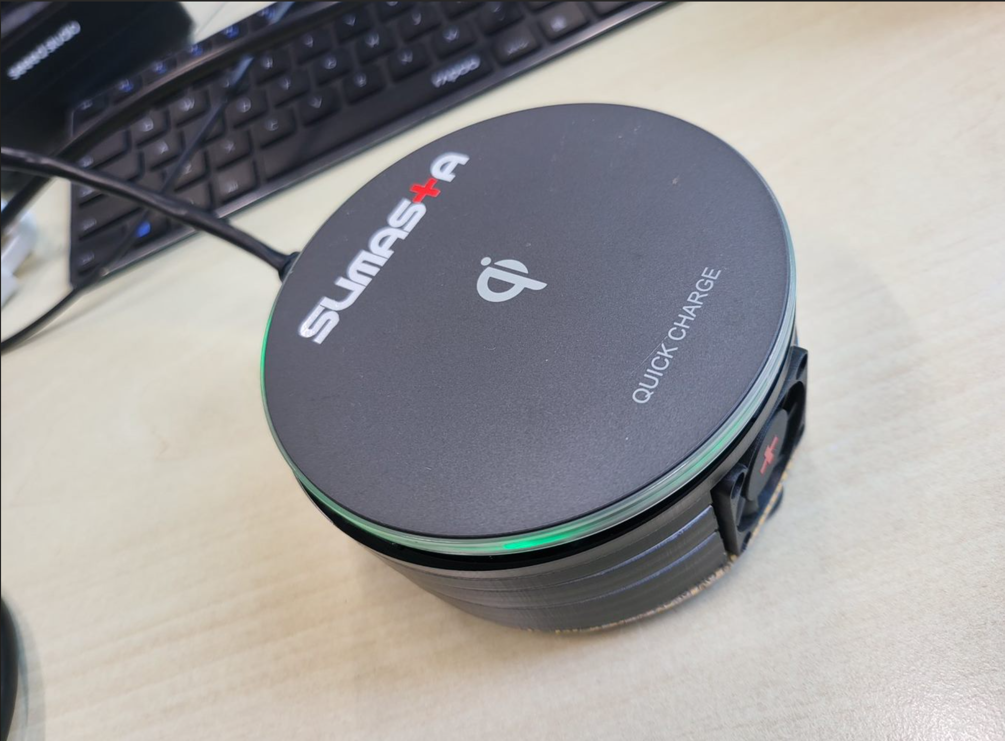
- Plugging the cable: As you can see the PoeQi powers-up immediately as soon as the Ethernet cable is plugged. And also almost immediately you can see the yellow LED blinks indicating immediately ethernet link activity.
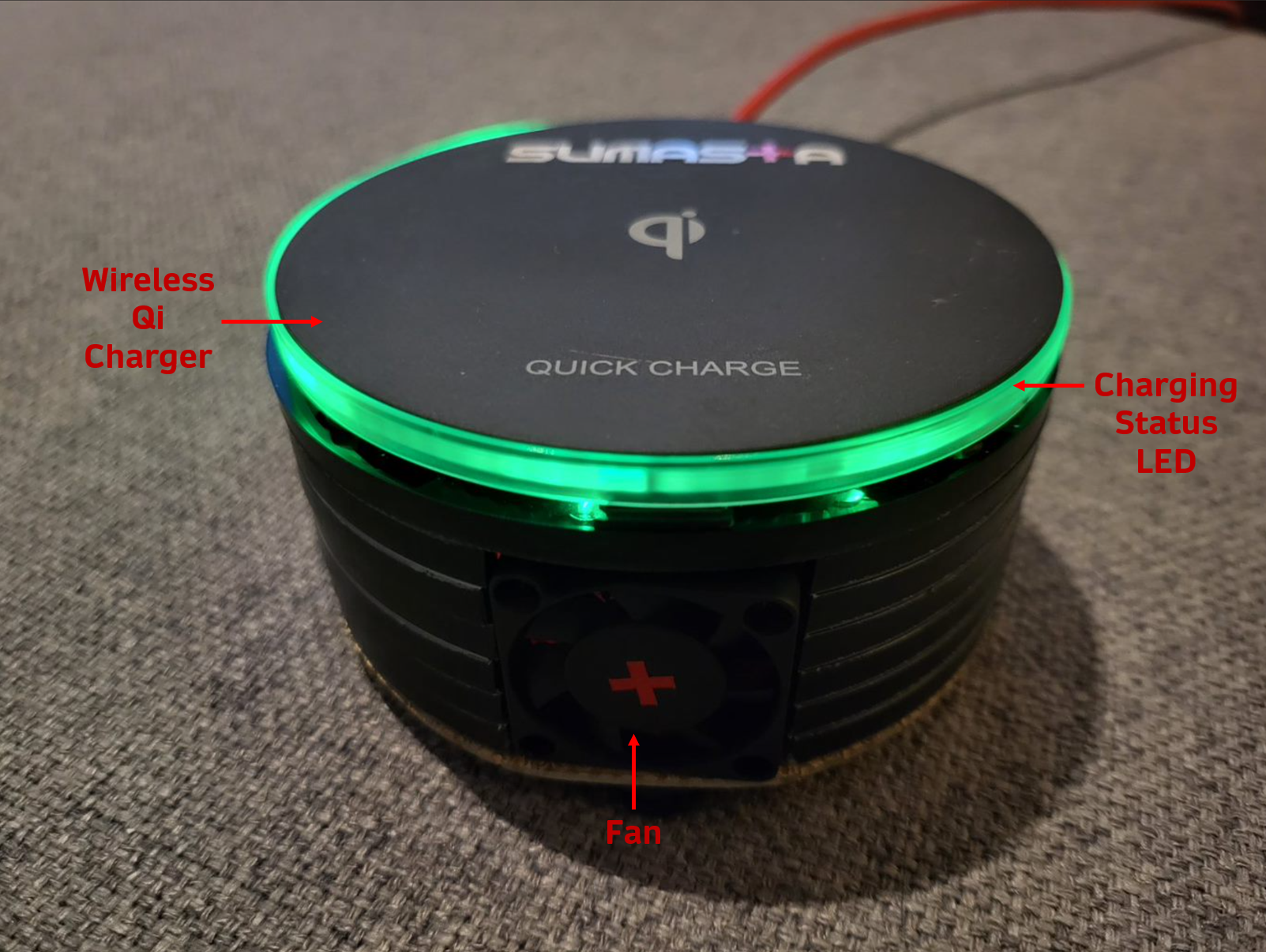
- Starts charging with a Samsung Flip Phone: You can see the circular green light changes to blue indicating the charging session has started. It is also confirmed on the small outer screen on the phone. If you look closely, you can also see the fan in front of it immediately starts as well.
- Starts Charging with a Samsung Ear Buds Case: Similar to the above, but charging a lower load device such as the ear buds case as shown below.
- Web-Client Notification: As soon as the charging starts, the webserver inside the PoeQi automatically adjust and get triggered as shown on the tablet screen. On the tablet screen you can see the current drawn for the wireless charging as well as the current temperature inside the housing close to the wireless qi charging and the PoE transformer.
- Stops Charging: As soon as the phone is removed, the charging stops indicated by the green light and also the fan stops rotating if you look closely.
Features
In a bit more details in pictures below you can see all the features
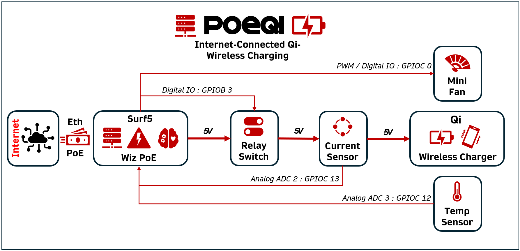
Schematic Diagram
Put it very simply, the overall schematic diagram can be summarized in figure below.
Specifications
- Wireless Qi Charging in Basic Power Profile (BPP) up to 5W
- PoE IEEE 802.3af Compliant enabled by WizPoE
- Surf5 Wiznet board powered by W7500 Microcontroller
- Mechanical relay switch for Qi charging, enabling ultra low power mode option
- PWM Controlled 3x3cm Fan
- AC712 analog current sensor
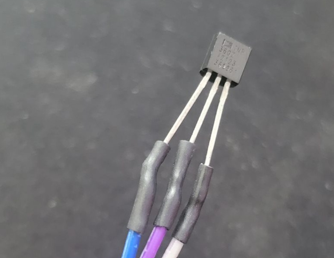
- TMP36 analog temperature sensor
- Laser cut acrylic wall housing
- Weight 209 grams
- Diameter 100mm
- Thickness 55mm
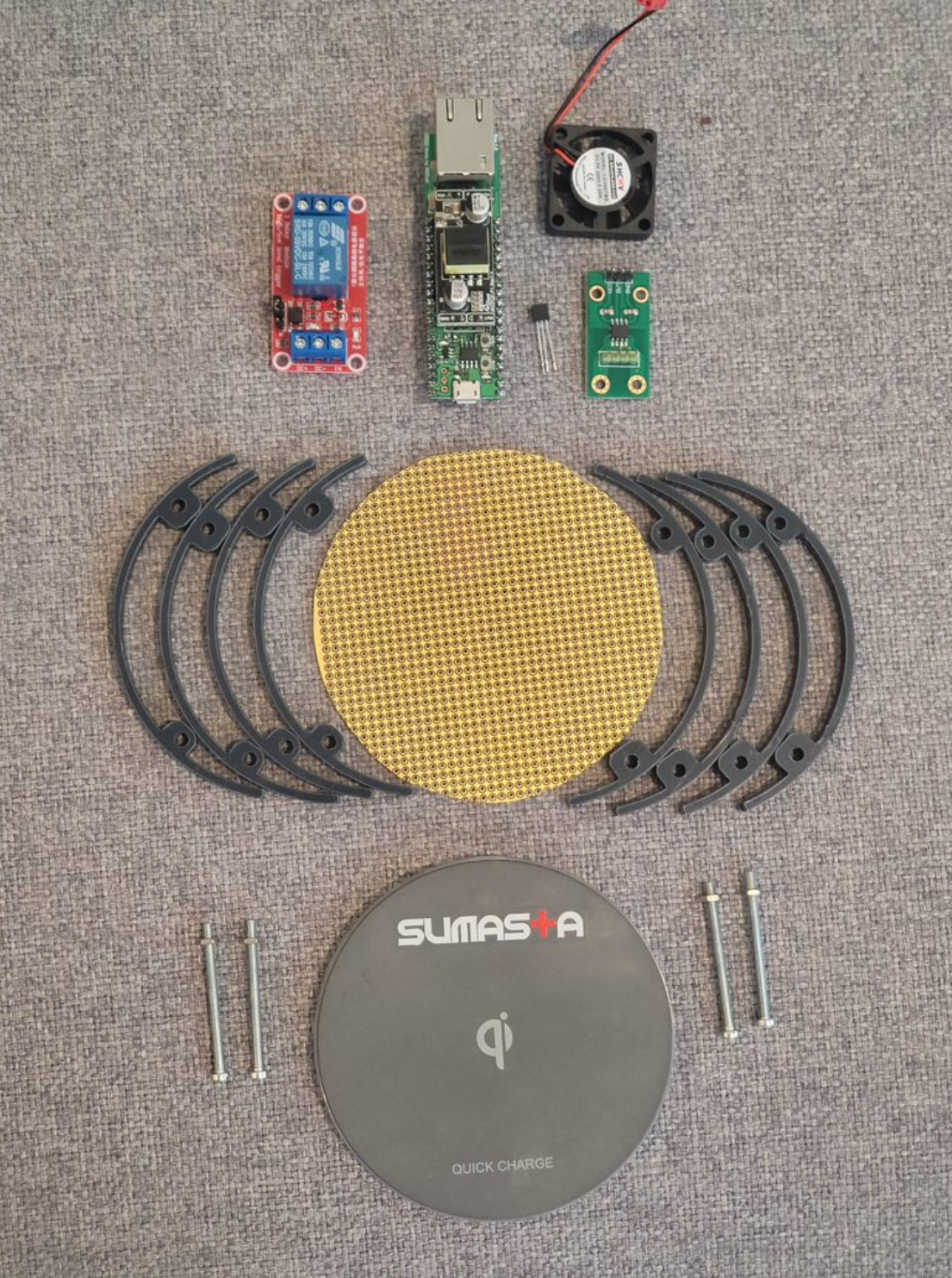
Bill-of-Materials
Thanks to the integration enabled by the Surf5 board and the Wiz-PoE module, there aren't many additional components or modules required for the PoeQi project. This streamlined design minimizes complexity and enhances reliability. Below is the complete list of components you'll need, along with links to where you can purchase them. Each link also provides more detailed specifications for each component, ensuring you have all the necessary information to proceed with your build:
- Wiznet Surf 5 Board: Contains the Ethernet PHY as well as W7500 microcontroller.
- WiZPoe Module: Enable Power over ethernet including its isolation circuit.
- 5V Relay module: Single channel relay board with protection and isolation circuits.
- Mini Fan: Tiny 5V fan 30x30x7mm fan normally used for Raspberry pi.
- AC712 Current Sensor: Analog current sensor board +/- 5 A.
- TMP36 Temperature Sensor: Analog temperature sensor.
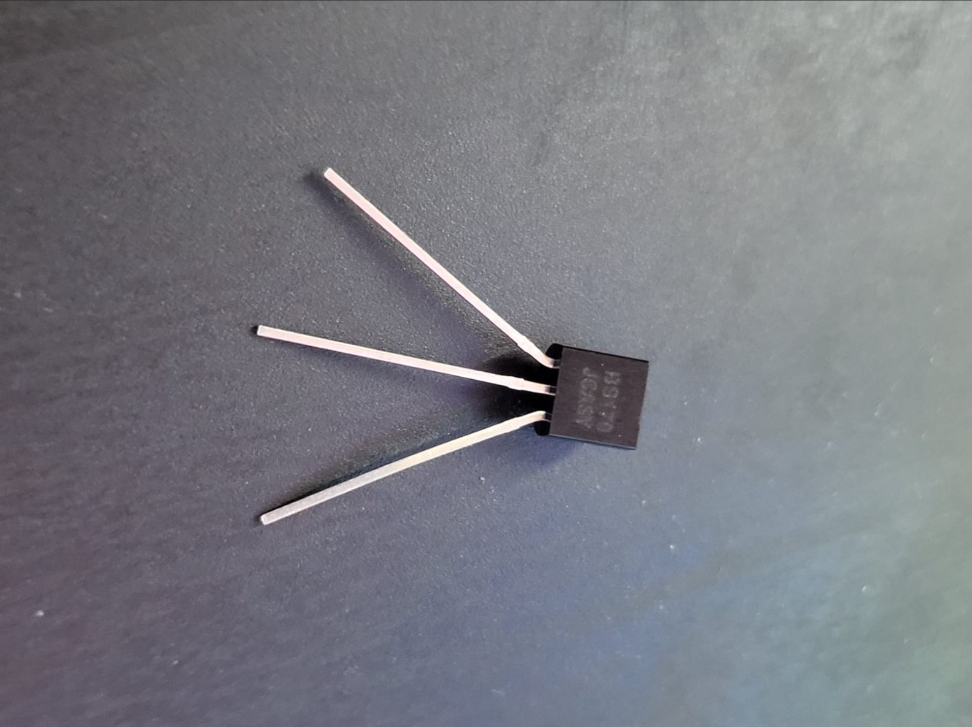
- N-FET BS170: N channel MOSFET 500mA for controlling the Fan speed.
- Wireless Qi Charger: You can choose any that suits you here, as long as it accepts 5V.
- Experiment perforated board: You can choose any type as well.
- Variety of DuPont Jumpers: Handy for making assembly pluggable.
- 40mm M3 Screws and nuts.
- 12 x laser cut wall housing, see in attachment below for the .dxf files.
Build Instructions
On this section the complete build instructions are detailed.
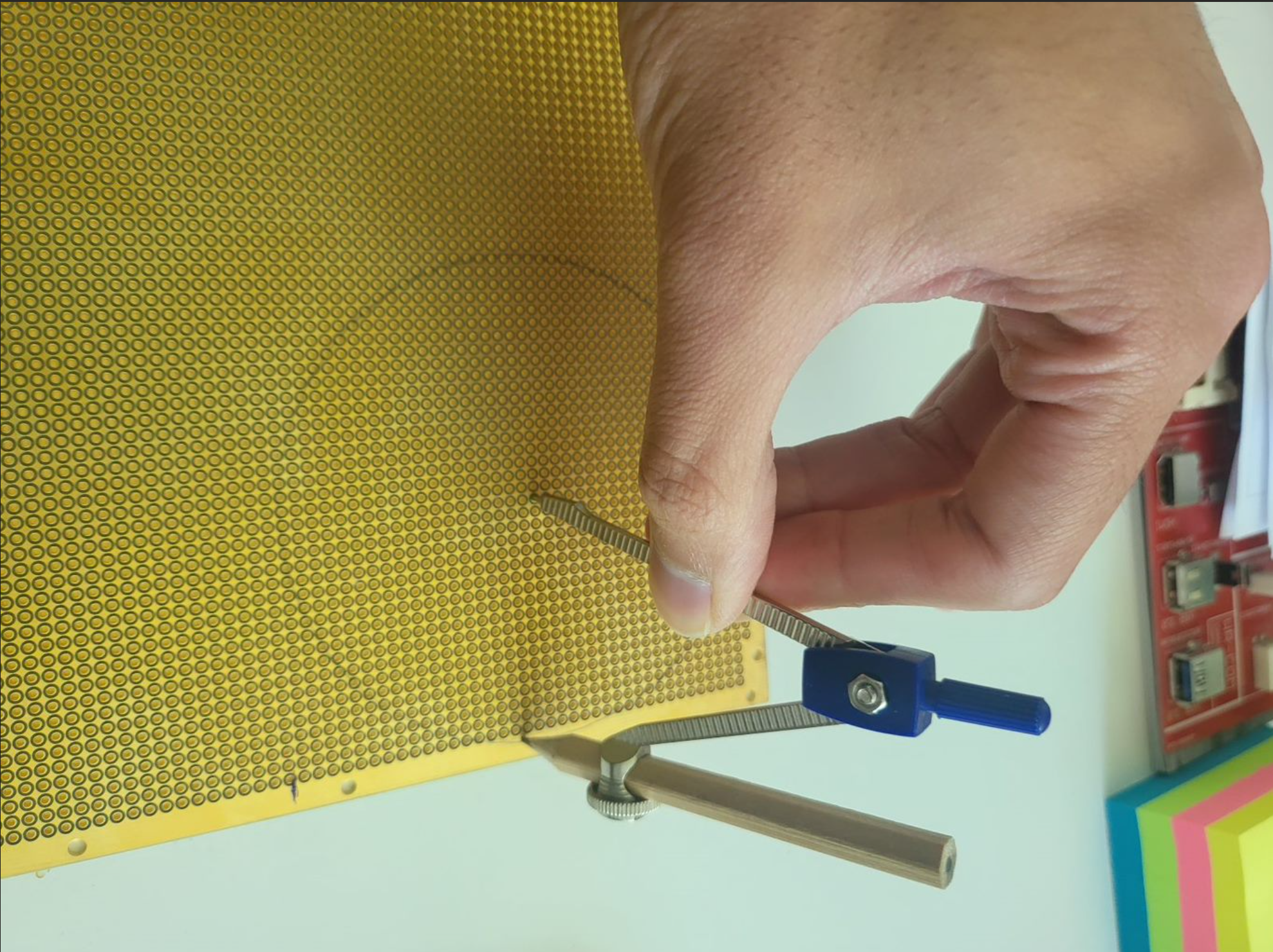
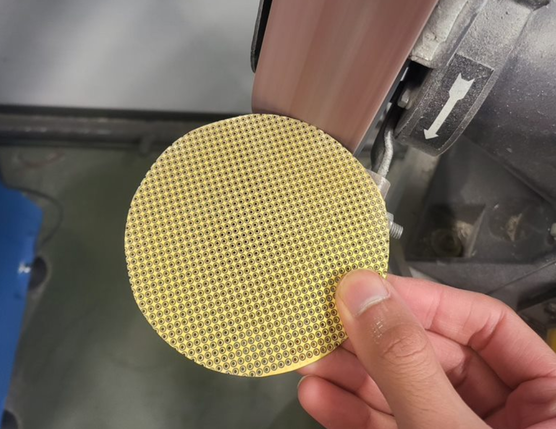
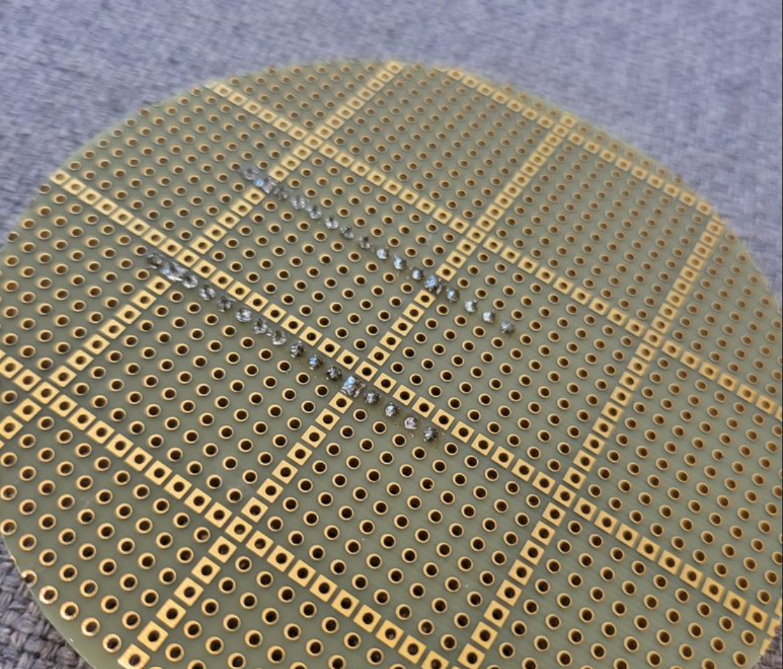
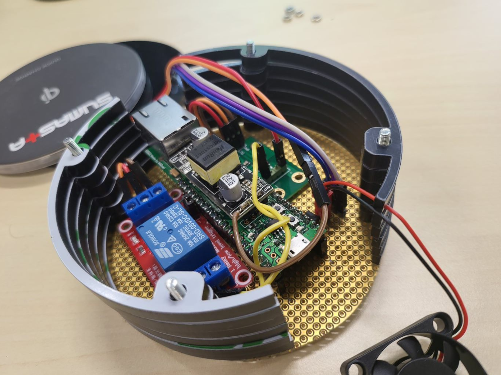
- Prepare the base experimentation circuit board. In this project I use a circular shape with a diameter of 100mm, you can can draw the outline with a protractor, cut and smoothly grind it with a grinder if you happened to have one.
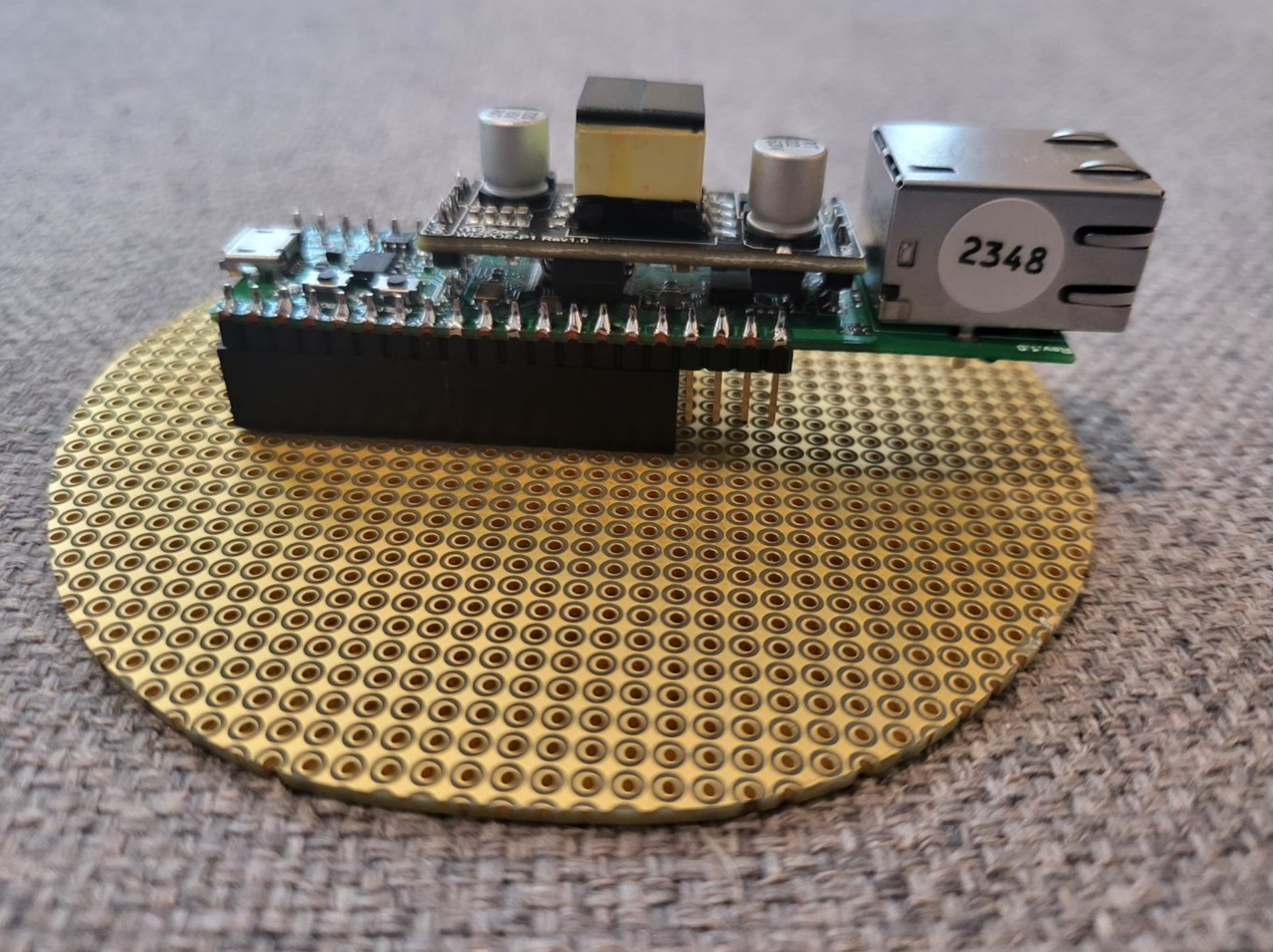
- Once the base PCB is ready and cleaned, the soldering of the surf5 board socket can be done. Make sure that the position is well in the center and the positioning of the module especially on the back side near the ethernet connector is well placed.
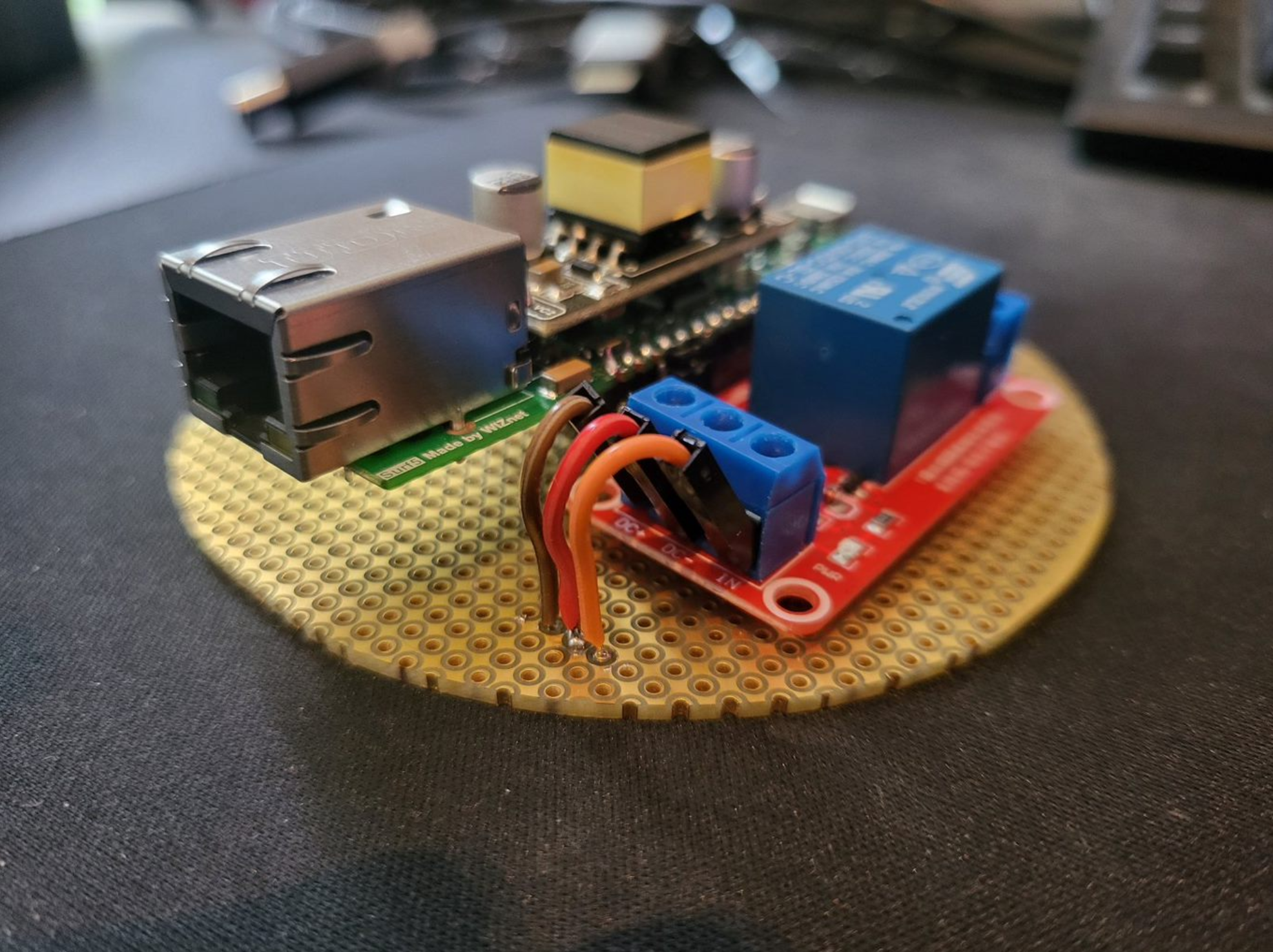
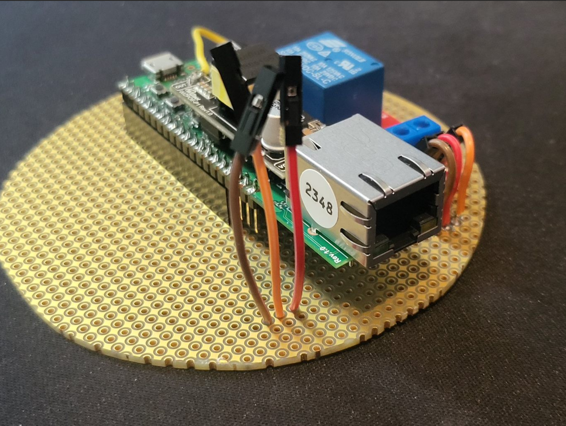
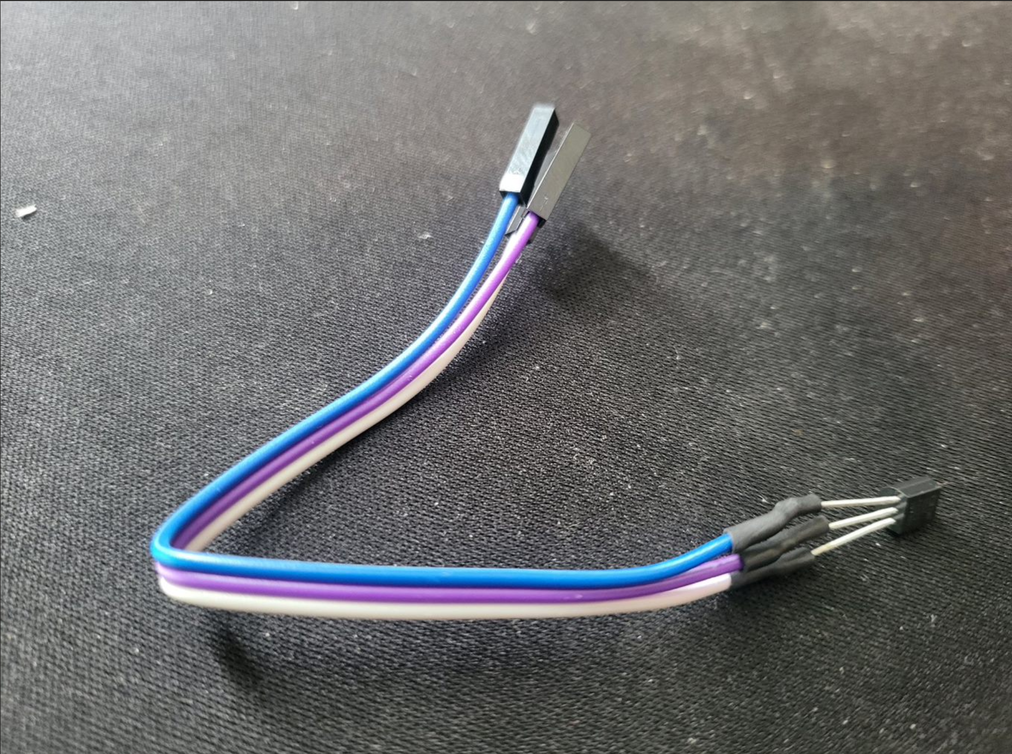
- Following that, we can prepare first the Relay module. Three wires must be mounted and eventually connected to the base PCB. We can use male dupont type jumper and cut the other end as shown in the picture below. We might need to bend the pins a bit to up, due to a bit of space constraint inside the housing.
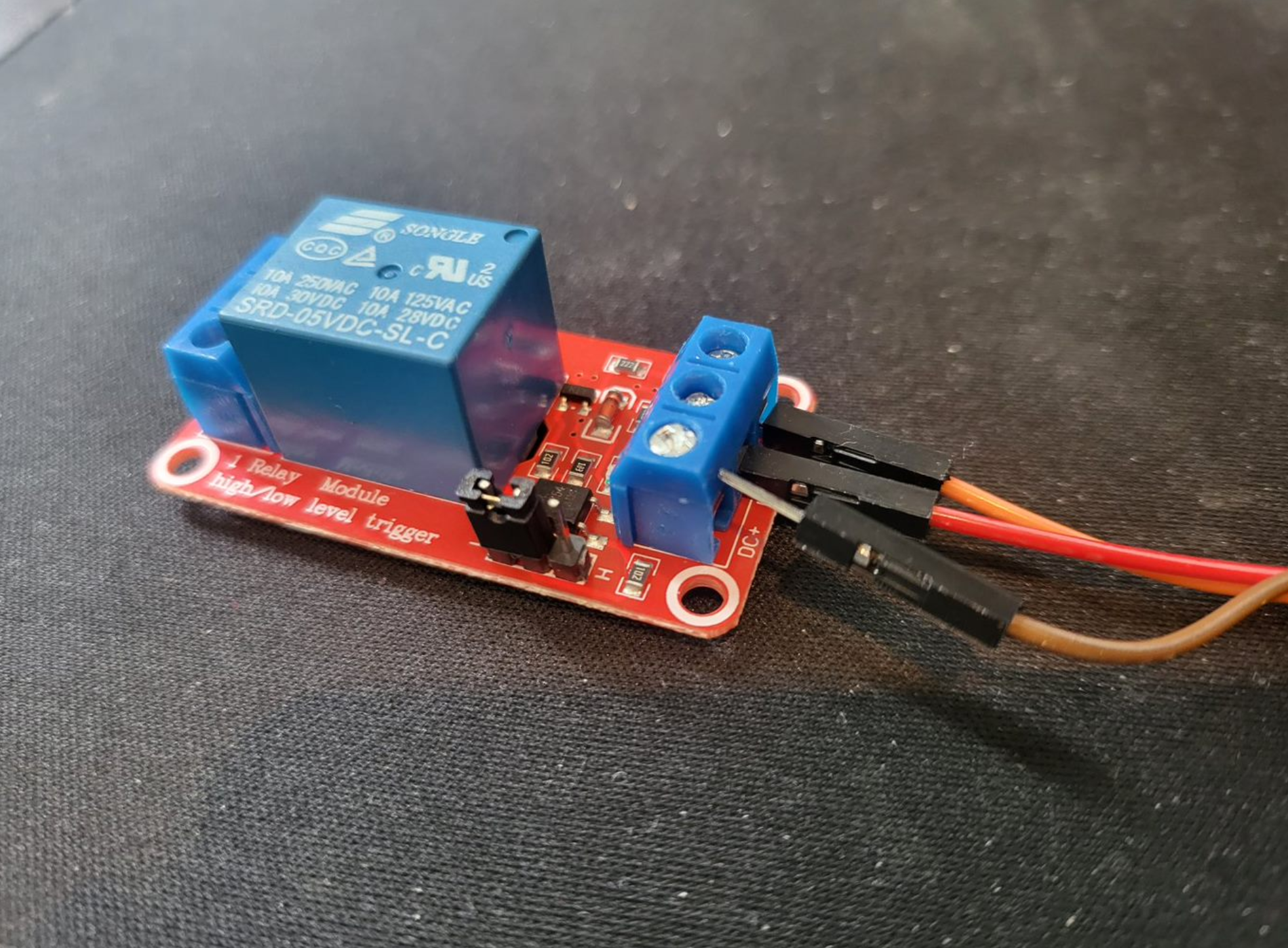
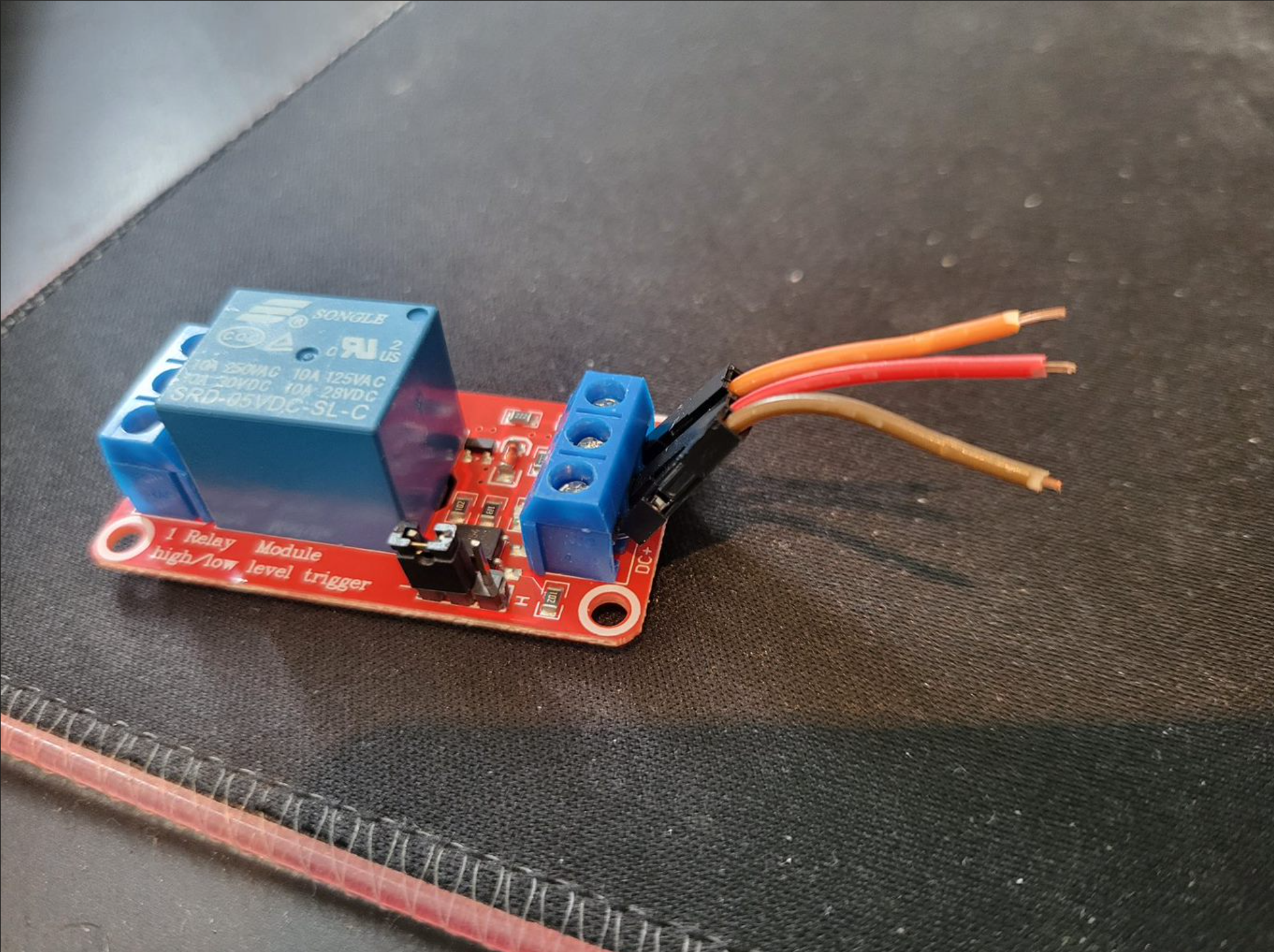
- Solder the three wires to the base PCB. Note that the three wires are the 5V, GND and Signal. The Brown is the 5V, RED is the GND and Orange is the signal. You can place a thick double sided tape or so underneath the relay module to make the module stays in place better. You can certainly also drill a hole on the base module to make it even more steady.
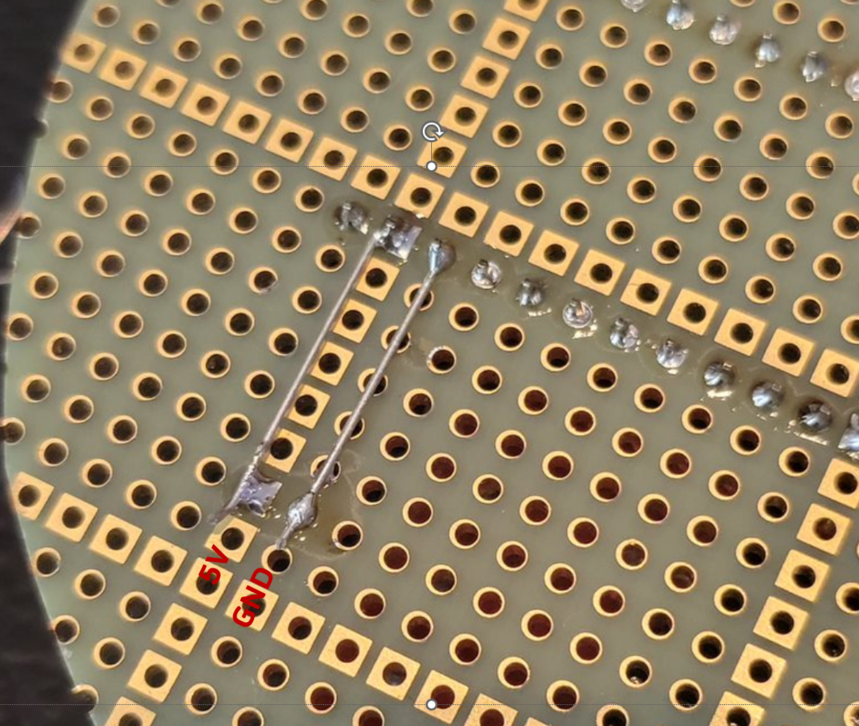
- Make a power bus of the Vsys 5V and the GND as shown below. Making a small power bus as shown below will come handy later on. You can use a lead of THT components e.g. resistor or caps to make the bridge bus.
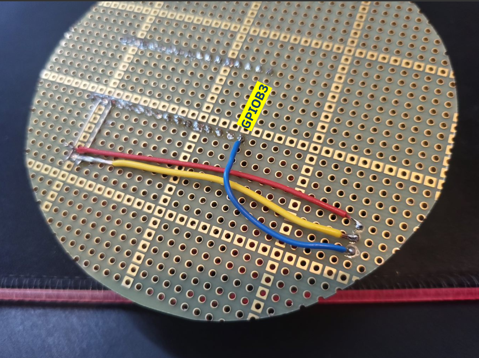
- Make the connection from the relay to the surf5 board. The three are the 5V, GND and the signal. It is important to note that the Relay pin in my board is connected to GPIOB3. The other two wires are for the 5V, with red wire and GND with yellow wire.
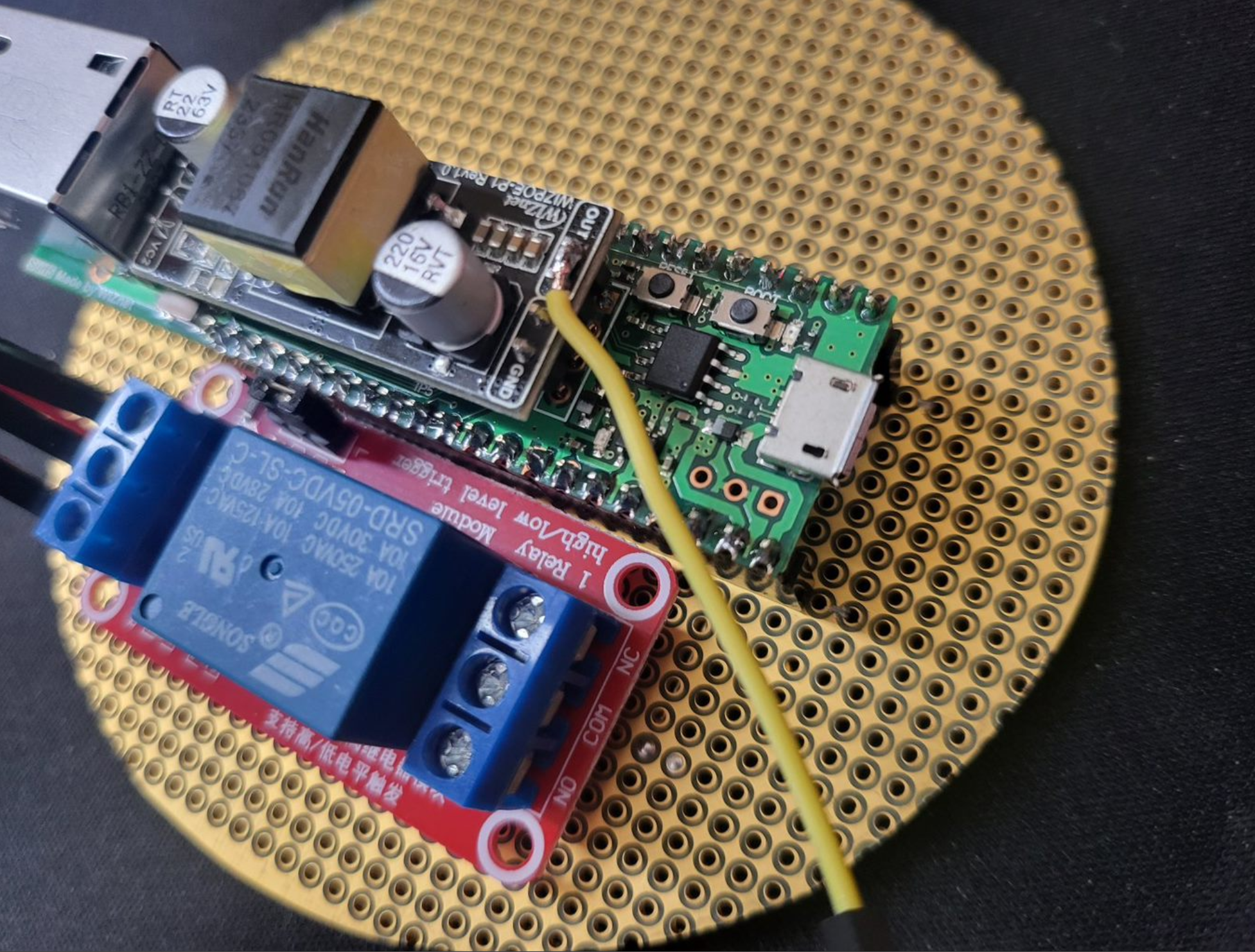
- On the top side, you can solder another dupont jumper with male pin from the out of the PoE module as shown below. This is the 5V Poe Out that will then go to the relay contact.
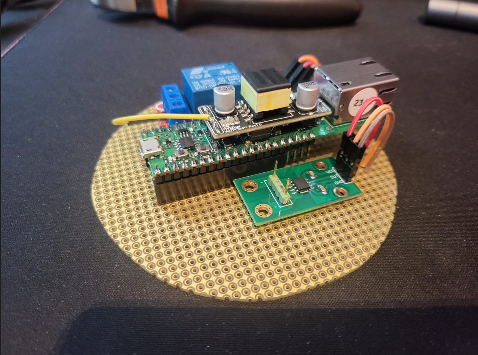
- Furthermore, on the opposite side of the surf5 board. We can prepare 3 wires to be connected to the current sensors as shown below. Preferably then this one you use female dupont jumper such that is can be plugged easily to the AC712 module.
- Once it is done, you can then place the AC712 sensor module next the the 3 wires as shown. Similar to the relay module, you can use simply a double sided tape on the back of drill a hole to make the mounting more firm. It is to note also earlier I soldered two pins male pin header as shown with the green header pin on the left side of the AC712 module.
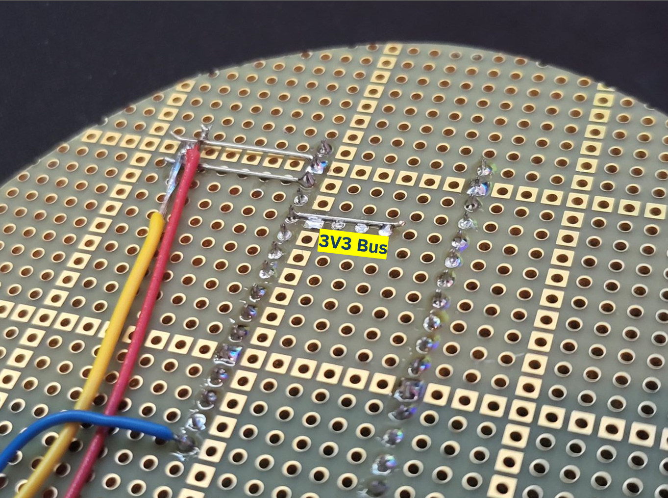
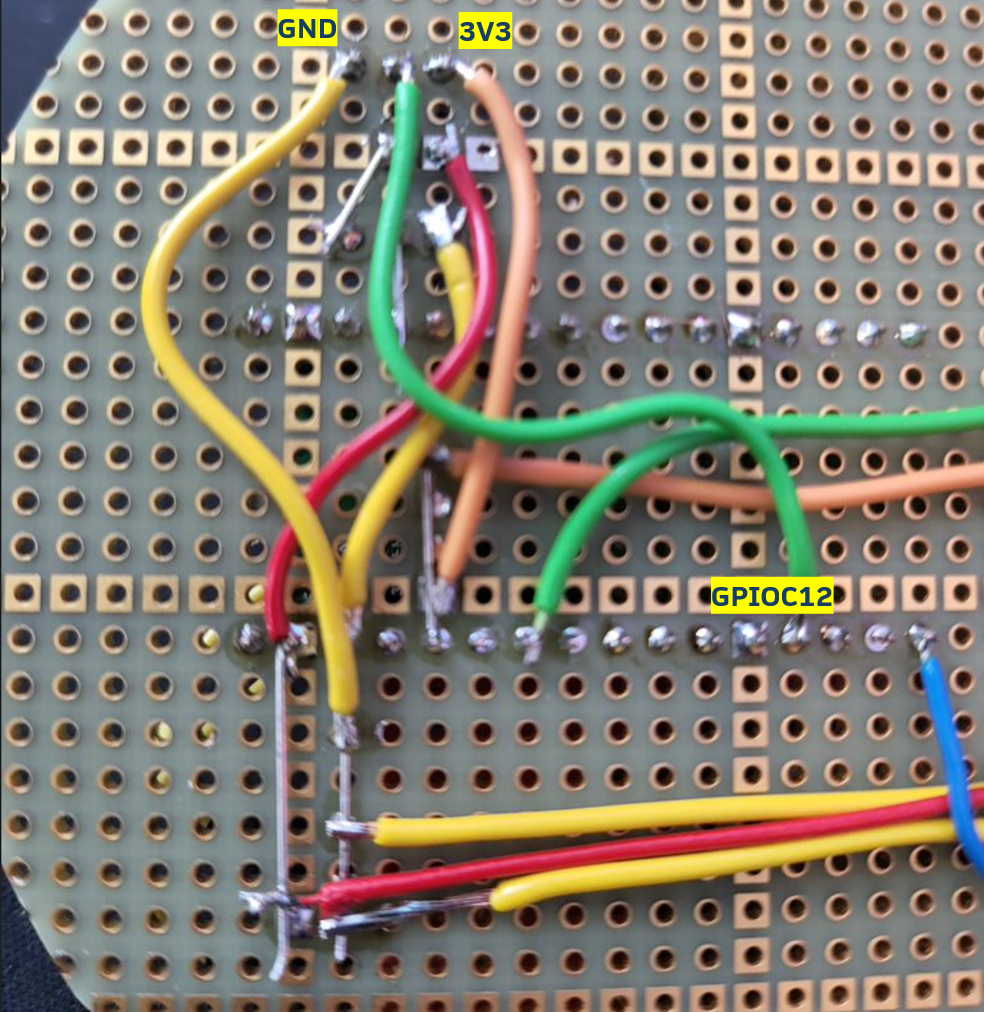
- Similar to the 5V bus, we also need to prepare 3v3 bus as most of the sensors runs on 3.3V. it can be as shown below.
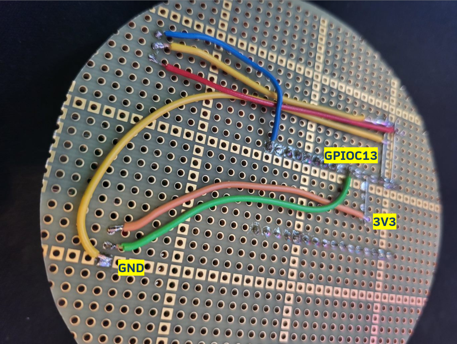
- Next step is then to solder and connect the pins from the AC712 sensor module. Picture below gives an example of how it can be done. The analog out of the sensor connects to the GPIOC13 / ADC2 of the surf5 board.
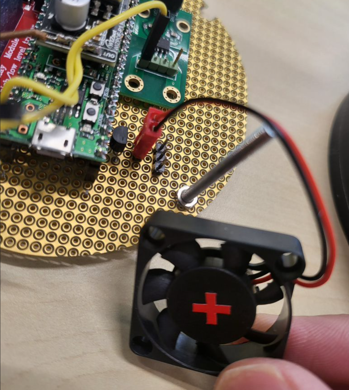
- Next one is to prepare the PWM controller for the fan. We'll need to take the BS170 FET and 2 pins male header and place it as shown in the pictures below.
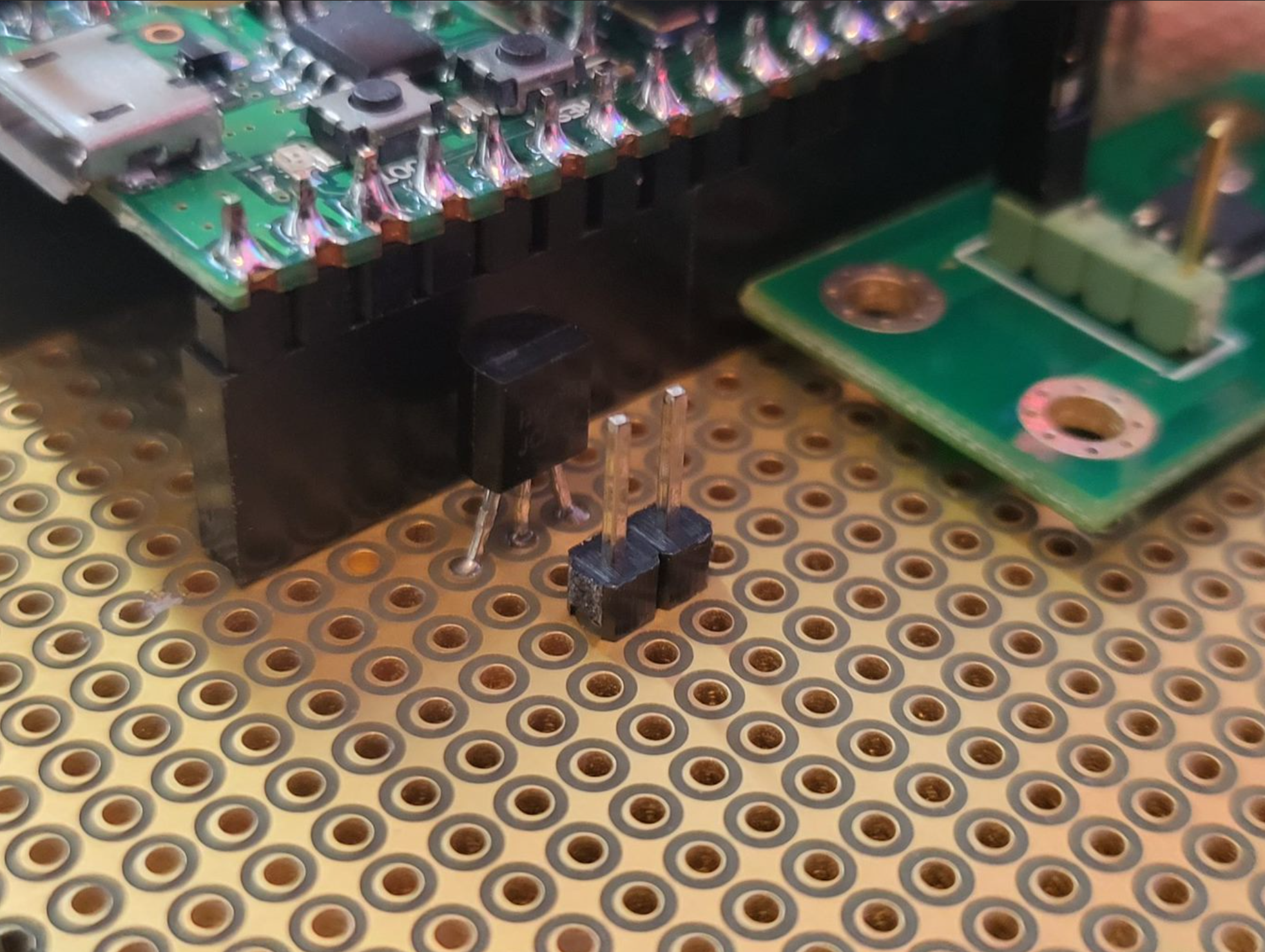
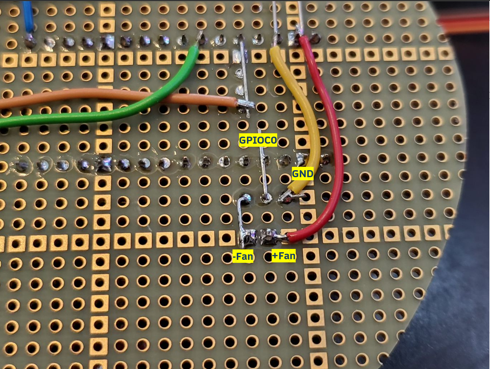
- On the bottom side, some wiring on the soldering must be done. In short the Gate of the FET is connected to GPIOC0 that is a PWM pin. The source connected to GND and the Gate to the Fan.
- Furthermore, we'll prepare the assembly of the TMP36 sensors. You can just mount it on the board, or place it remotely with wires. I prefer to do it with wires as you can place it near the hottest part of the unit, which is likely the PoE module and Wireless Qi charging coil.
- Following that, three pins male pin header must then be soldered on the base board. I placed it next to the fan connector. Note the GPIOC12 connector on the picture is still soldered wrong, it must be connected to one more pin to the left.
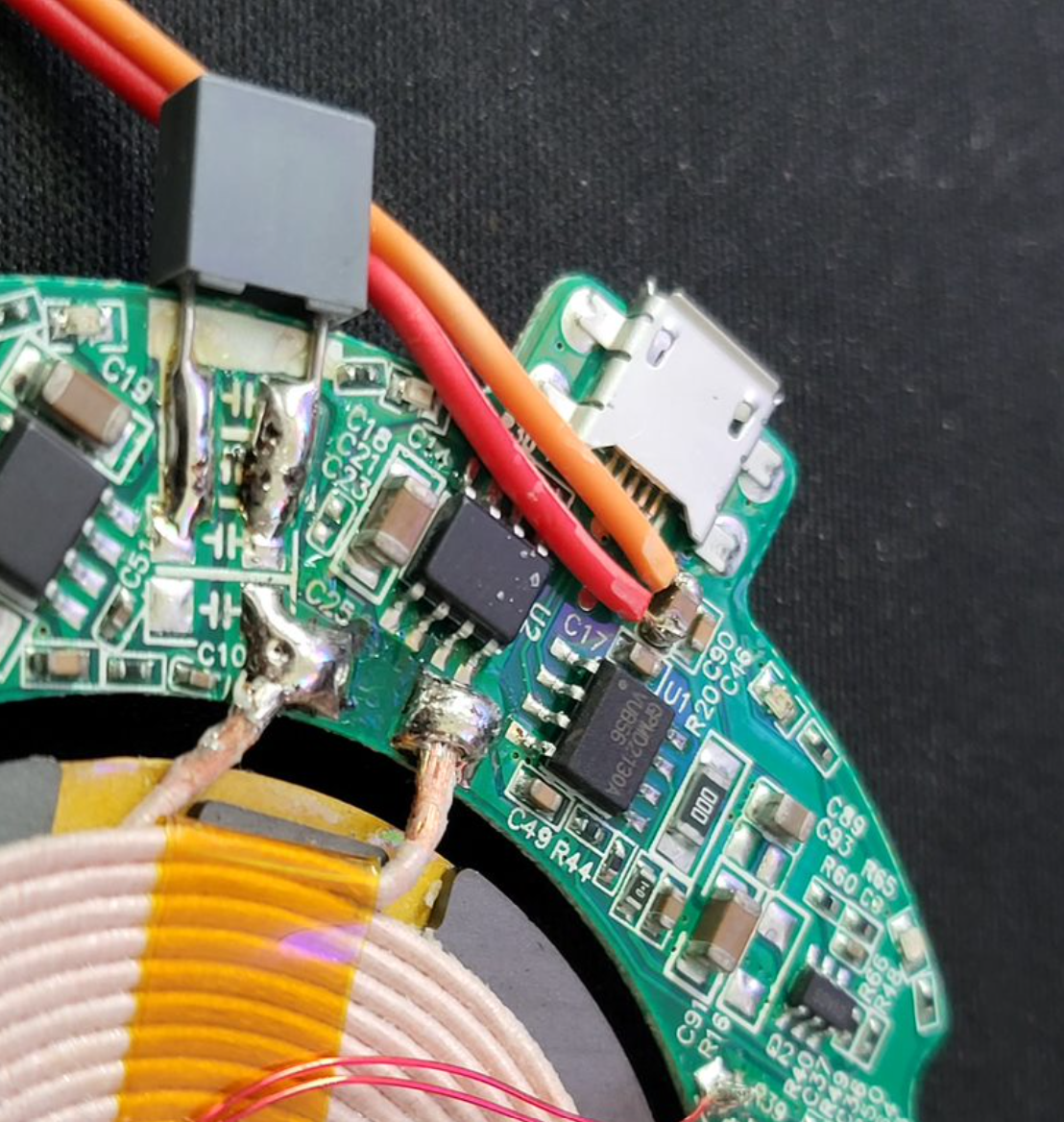
- Solder the 5V power input pins to the Wireless charger input circuitry. This one you have to take care and check where is the input 5V and GND of the wireless Qi charger. If you have ones with micro USB connector it is typically easier to find as shown in the picture below. I soldered the two pins next to the input capacitor.
- At this moment, all the soldering job is done! It is just a matter of assembling the wiring and housing.
- From the top side, we can first connect the fan.
- Followed by the temperature sensor TMP36. As you can see, I decided to place the TMP sensor inside the cavity of the top cover just to have the maximum ambient temperature reading inside.
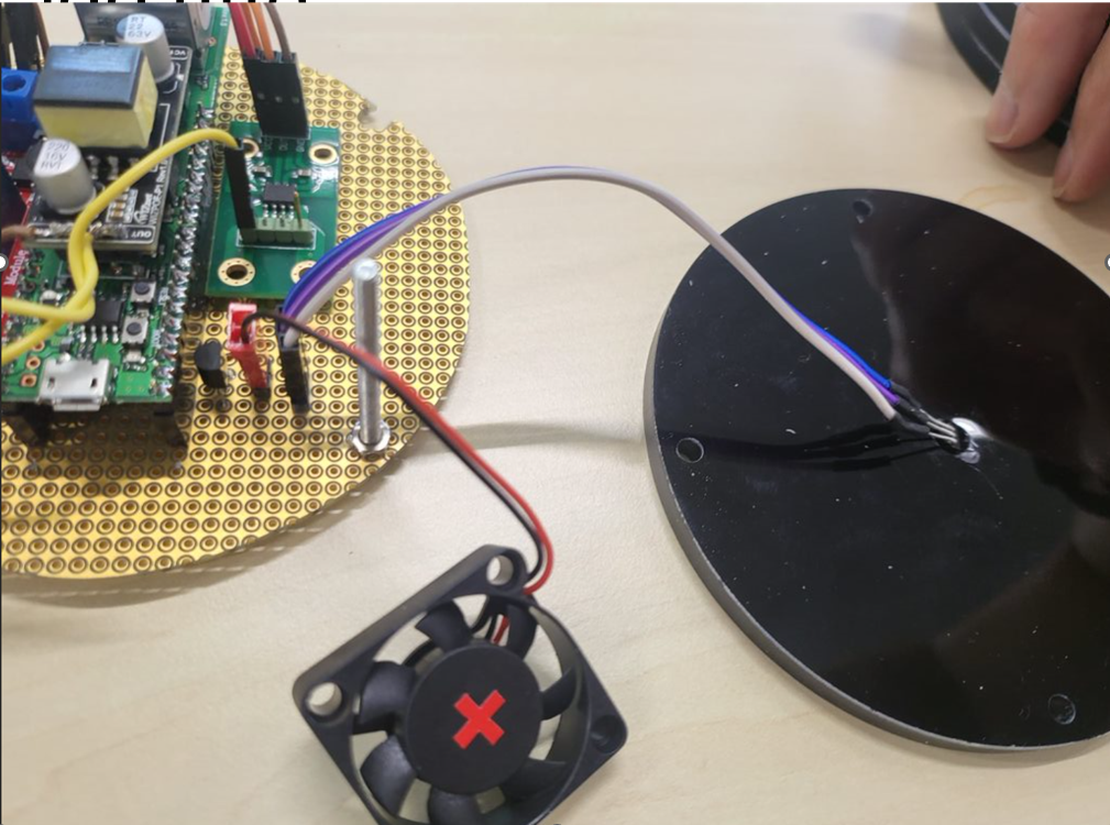
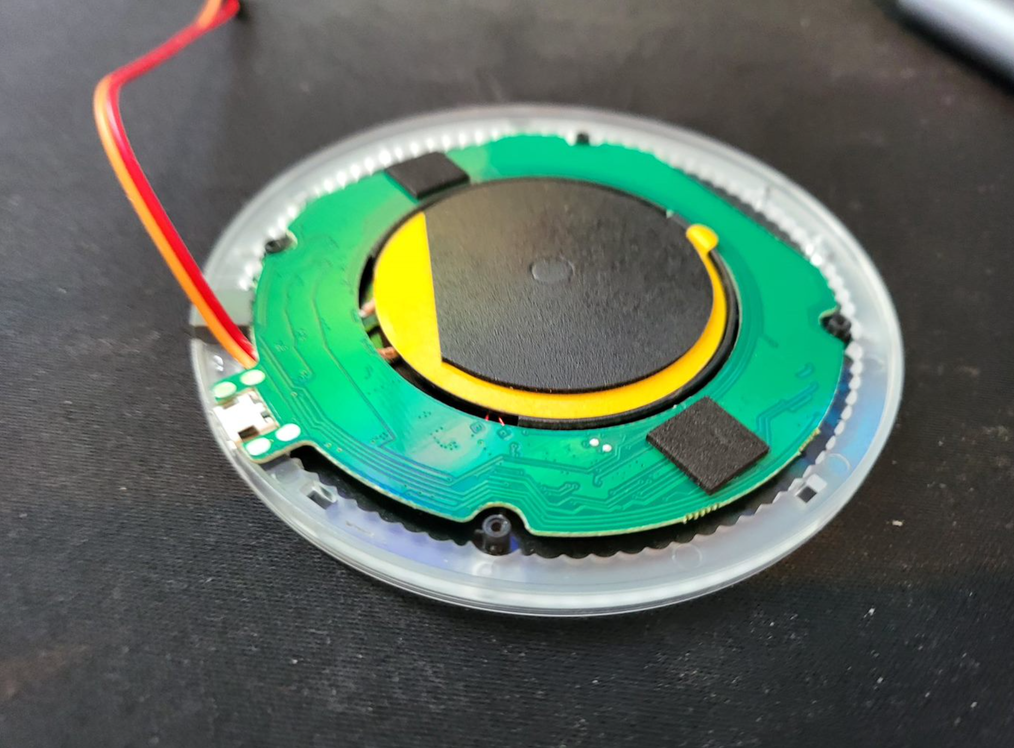
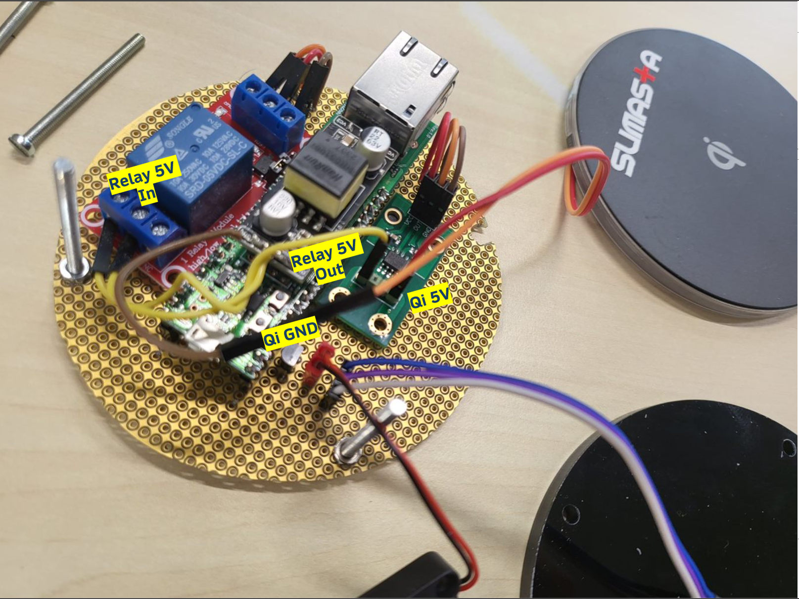
- Last but not least, the connections to the wireless Qi charging then must be made as well. First, the GND connection from the PoE module (brown wire) can be connected to the orange cable which is the Qi GND connection. Furthermore, the 5V Qi must be connected to the output side of the AC712 module as shown by the red wire coming out of the Qi module. At last the 5V relay In and Out must be connected accordingly as shown. Both must be connected to the COM and NO part of the relay, though they are interchangeable.
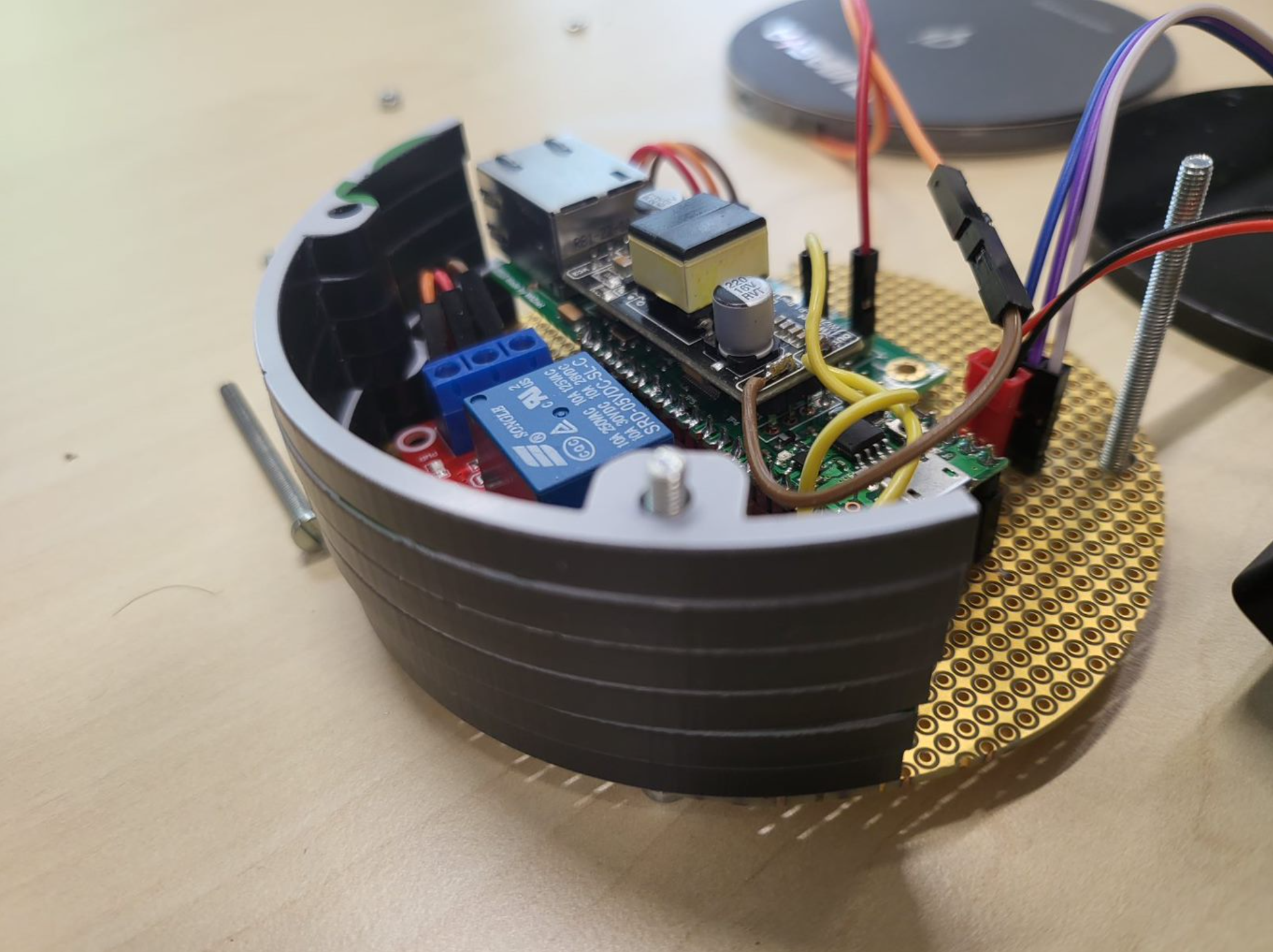
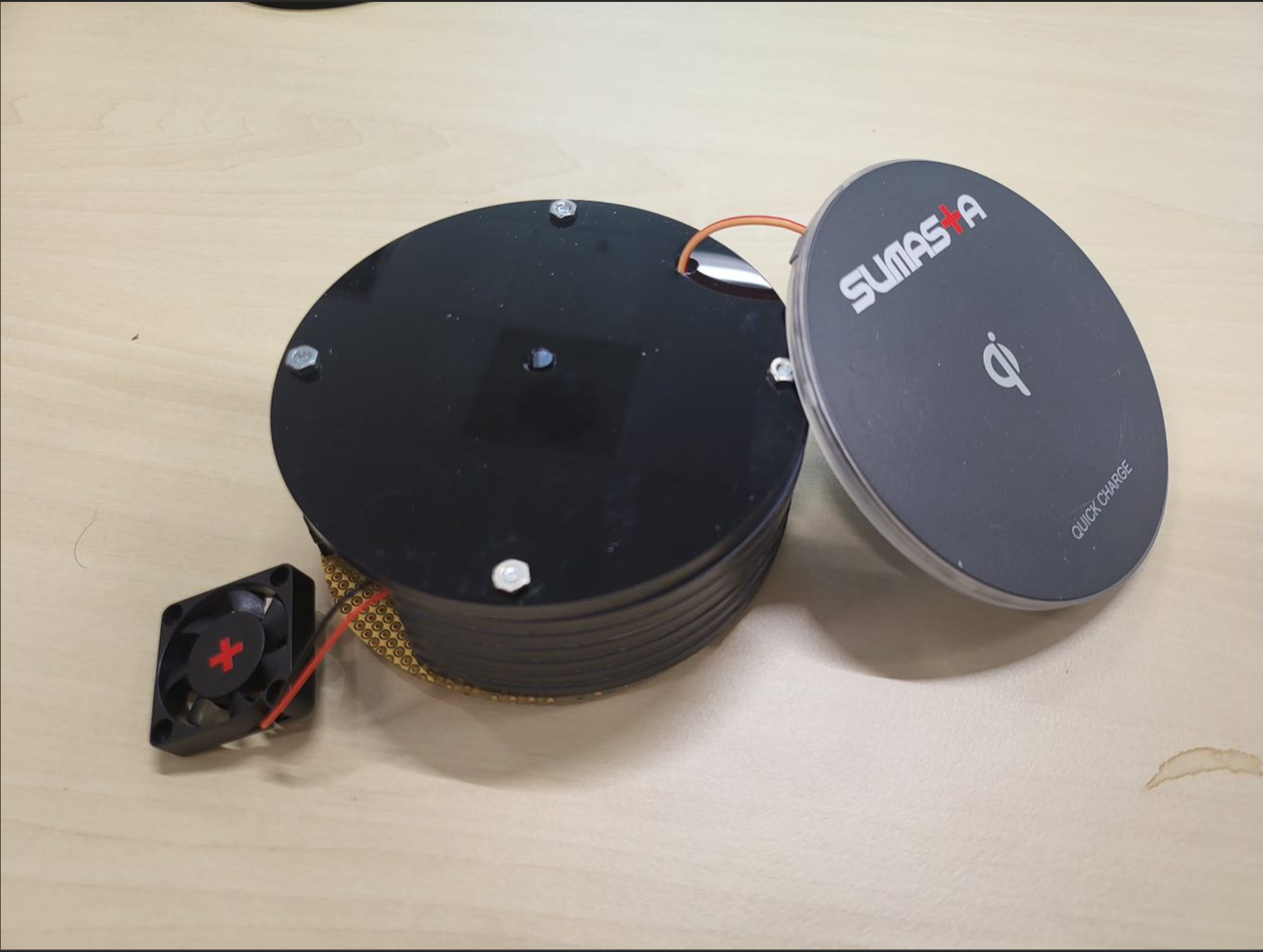
- At the very last, the stack up of the assembly can be done. Started with one side of the wall, then the other side, finalized by placing the top cover. I believe the pictures below is quite self-explanatory.
Program
In general, the coding is quite simple, thanks to the WizTOE Webserver example from by the Wiznet team. In general there are only few modifications needed if you want the PoeQi to just act as a webserver. Surely you can also expand it to other connected devices as well if you want.
There are four major steps on the programming side:
1. Setup the GPIOs:
- 2 x ADC Ports
- 1 x IO / PWM for the Fan
- 1 x IO for the Relay
/**
 * @brief  Configures the GPIO Peripheral.
 * @note   GPIO pin configures for ADC and GPIO for controlling relay and Fan
 * @param  None
 * @retval None
 */
static void GPIO_Config(void)
{
    GPIO_InitTypeDef GPIO_InitStructure;

    GPIO_InitStructure.GPIO_Pin = GPIO_Pin_8 | GPIO_Pin_9 | GPIO_Pin_13 | GPIO_Pin_14;
    GPIO_InitStructure.GPIO_Direction = GPIO_Direction_IN;
    GPIO_InitStructure.GPIO_Pad = GPIO_Pad_Default;
    GPIO_InitStructure.GPIO_AF = PAD_AF0;
    GPIO_Init(GPIOC, &GPIO_InitStructure);

    GPIO_InitStructure.GPIO_Pin = GPIO_Pin_0;
    GPIO_InitStructure.GPIO_Direction = GPIO_Direction_OUT;
    GPIO_InitStructure.GPIO_Pad = GPIO_Pad_Default;
    GPIO_InitStructure.GPIO_AF = PAD_AF1;
    GPIO_Init(GPIOC, &GPIO_InitStructure);

    GPIO_InitStructure.GPIO_Pin = GPIO_Pin_3;
    GPIO_InitStructure.GPIO_Direction = GPIO_Direction_OUT;
    GPIO_InitStructure.GPIO_AF = PAD_AF1;
    GPIO_Init(GPIOB, &GPIO_InitStructure); // relay

    GPIO_SetBits(GPIOB, GPIO_Pin_3); // Disable Relay
    GPIO_ResetBits(GPIOC, GPIO_Pin_0); // Disable Fan

}
2. Sensor reading functions
First one is for reading the current reading. Function below returns the amps sensor in milliamps.
/**
 * @brief  Gets the charging current
 * @param  None
 * @retval Charging rate in milliamps
 */
int getChargingCurrent(){

    ADC_Cmd(ENABLE);
    ADC_ChannelConfig(2);
    ADC_StartOfConversion();
    uint16_t currentADC = ADC_GetConversionValue();
    ADC_Cmd(DISABLE);

    printf("ADC : %u \r\n",  currentADC);

    double currentMv = ((int) currentADC - 2048) * 0.805;
    int intCurrentMv = (int)currentMv;

    float currentMAmp = (currentMv * 1000 / 185.0);
    int intCurrentMAmp = (int) currentMAmp;

    return intCurrentMAmp;

}
Second one for reading the temperature. Function below returns the temperature in integer for simplicity.
/**
 * @brief  Gets the current temperature reading
 * @param  None
 * @retval Temperature reading in celcius, integer.
 */
int getTemperature(){
    ADC_Cmd(ENABLE);
    ADC_ChannelConfig(3);
    ADC_StartOfConversion();
    uint16_t currentADC = ADC_GetConversionValue();
    ADC_Cmd(DISABLE);
    int temperature = (currentADC-600)/10;
    return temperature;
}
3. Charging status function
It is a binary function to check whether the charging is ongoing or not.
/**
 * @brief  Get the charging status.
 * @param  None
 * @retval Integer binary charging state
 */
int isCharging(){

    ADC_Cmd(ENABLE);
    ADC_ChannelConfig(2);
    ADC_StartOfConversion();
    uint16_t currentADC = ADC_GetConversionValue();
    if(currentADC>2100){
        return 1;
    }else{
        return 0;
    }
    ADC_Cmd(DISABLE);

}
4. Web server charging details.
The function takes several status parameters and encapsulate it in a simple HTML. You can easily extend this to make more intuitive web interface.
/**
 * @brief  WebServer example function.
 * @note
 * @param  sn: Socket number to use.
 * @param  buf: The buffer the socket will use.
 * @param  port: Socket port number to use.
 * @param icharging: Status of the charging in binary
 * @param chargingCurrent: current charging rate in mA
 * @param temperature: Current charging temperature in Celcius. Integer.
 * @retval Success or Fail of configuration functions
 */
int32_t WebServerCharger(uint8_t sn, uint8_t* buf, uint16_t port, int isCharging, int chargingCurrent, int temperature)
{
    uint8_t i;
    uint8_t adcChannelOffset = 2;
    int32_t ret;
    uint16_t size = 0;
    uint8_t destip[4];
    uint16_t destport;
    uint8_t adc_buf[128] = { '\0', };

    switch (getSn_SR(sn))
    {
        case SOCK_ESTABLISHED:

            if (getSn_IR(sn) & Sn_IR_CON) {

                getSn_DIPR(sn, destip);
                destport = getSn_DPORT(sn);
                printf("%d:Connected - %d.%d.%d.%d : %d\r\n", sn, destip[0], destip[1], destip[2], destip[3], destport);

                setSn_IR(sn, Sn_IR_CON);
            }

            if ((size = getSn_RX_RSR(sn)) > 0) {
                if (size > DATA_BUF_SIZE) size = DATA_BUF_SIZE;
                ret = recv(sn, buf, size);
                if (ret <= 0) return ret;
                printf("%s", buf);

                ret = send(sn, "HTTP/1.1 200 OK\r\n"
                        "Content-Type: text/html\r\n"
                        "Connection: close\r\n"
                        "Refresh: 5\r\n"
                        "\r\n"
                        "<!DOCTYPE HTML>\r\n"
                        "<html>\r\n", sizeof("HTTP/1.1 200 OK\r\n"
                        "Content-Type: text/html\r\n"
                        "Connection: close\r\n"
                        "Refresh: 5\r\n"
                        "\r\n"
                        "<!DOCTYPE HTML>\r\n"
                        "<html>\r\n") - 1);
                if (ret < 0) {
                    close(sn);
                    return ret;
                }

                if (isCharging==1){
                    sprintf(adc_buf, "Now Charging with %d mA <br />\r\n", chargingCurrent);
                    ret = send(sn, adc_buf, strlen(adc_buf));
                    if (ret < 0) {
                        close(sn);
                        return ret;
                    }
                    memset(adc_buf, '\0', 128);

                    sprintf(adc_buf, "Charging Temperature: %d Celcius <br />\r\n", temperature);
                    ret = send(sn, adc_buf, strlen(adc_buf));
                    if (ret < 0) {
                        close(sn);
                        return ret;
                    }
                    memset(adc_buf, '\0', 128);

                }else{
                    sprintf(adc_buf, "Not Charging <br/>\r\n");
                    ret = send(sn, adc_buf, strlen(adc_buf));
                    if (ret < 0) {
                        close(sn);
                        return ret;
                    }
                    memset(adc_buf, '\0', 128);
                }

                ret = send(sn, "</html>\r\n", sizeof("</html>\r\n") - 1);
                if (ret < 0) {
                    close(sn);
                    return ret;
                }

                disconnect(sn);
            }

            break;
        case SOCK_CLOSE_WAIT:

            if ((ret = disconnect(sn)) != SOCK_OK) return ret;

            printf("%d:Socket Closed\r\n", sn);

            break;
        case SOCK_INIT:

            printf("%d:Listen, Web server, port [%d]\r\n", sn, port);

            if ((ret = listen(sn)) != SOCK_OK) return ret;

            break;
        case SOCK_CLOSED:

            if ((ret = socket(sn, Sn_MR_TCP, port, 0x00)) != sn) return ret;

            break;
        default:
            break;
    }
    return 1;
}
5. Main Loop
Lastly is the main loop that keeps the program running continuously. And the logic is pretty simple. It waits until current through the Qi charger goes above a certain threshold or not. If so then it start activating the fan and update contents of the HTML web server accordingly.
/**
 * @brief  WebServer example function.
 * @note
 * @param  sn: Socket number to use.
 * @param  buf: The buffer the socket will use.
 * @param  port: Socket port number to use.
 * @param icharging: Status of the charging in binary
 * @param chargingCurrent: current charging rate in mA
 * @param temperature: Current charging temperature in Celcius. Integer.
 * @retval Success or Fail of configuration functions
 */
int32_t WebServerCharger(uint8_t sn, uint8_t* buf, uint16_t port, int isCharging, int chargingCurrent, int temperature)
{
    uint8_t i;
    uint8_t adcChannelOffset = 2;
    int32_t ret;
    uint16_t size = 0;
    uint8_t destip[4];
    uint16_t destport;
    uint8_t adc_buf[128] = { '\0', };

    switch (getSn_SR(sn))
    {
        case SOCK_ESTABLISHED:

            if (getSn_IR(sn) & Sn_IR_CON) {

                getSn_DIPR(sn, destip);
                destport = getSn_DPORT(sn);
                printf("%d:Connected - %d.%d.%d.%d : %d\r\n", sn, destip[0], destip[1], destip[2], destip[3], destport);

                setSn_IR(sn, Sn_IR_CON);
            }

            if ((size = getSn_RX_RSR(sn)) > 0) {
                if (size > DATA_BUF_SIZE) size = DATA_BUF_SIZE;
                ret = recv(sn, buf, size);
                if (ret <= 0) return ret;
                printf("%s", buf);

                ret = send(sn, "HTTP/1.1 200 OK\r\n"
                        "Content-Type: text/html\r\n"
                        "Connection: close\r\n"
                        "Refresh: 5\r\n"
                        "\r\n"
                        "<!DOCTYPE HTML>\r\n"
                        "<html>\r\n", sizeof("HTTP/1.1 200 OK\r\n"
                        "Content-Type: text/html\r\n"
                        "Connection: close\r\n"
                        "Refresh: 5\r\n"
                        "\r\n"
                        "<!DOCTYPE HTML>\r\n"
                        "<html>\r\n") - 1);
                if (ret < 0) {
                    close(sn);
                    return ret;
                }

                if (isCharging==1){
                    sprintf(adc_buf, "Now Charging with %d mA <br />\r\n", chargingCurrent);
                    ret = send(sn, adc_buf, strlen(adc_buf));
                    if (ret < 0) {
                        close(sn);
                        return ret;
                    }
                    memset(adc_buf, '\0', 128);

                    sprintf(adc_buf, "Charging Temperature: %d Celcius <br />\r\n", temperature);
                    ret = send(sn, adc_buf, strlen(adc_buf));
                    if (ret < 0) {
                        close(sn);
                        return ret;
                    }
                    memset(adc_buf, '\0', 128);

                }else{
                    sprintf(adc_buf, "Not Charging <br/>\r\n");
                    ret = send(sn, adc_buf, strlen(adc_buf));
                    if (ret < 0) {
                        close(sn);
                        return ret;
                    }
                    memset(adc_buf, '\0', 128);
                }

                ret = send(sn, "</html>\r\n", sizeof("</html>\r\n") - 1);
                if (ret < 0) {
                    close(sn);
                    return ret;
                }

                disconnect(sn);
            }

            break;
        case SOCK_CLOSE_WAIT:

            if ((ret = disconnect(sn)) != SOCK_OK) return ret;

            printf("%d:Socket Closed\r\n", sn);

            break;
        case SOCK_INIT:

            printf("%d:Listen, Web server, port [%d]\r\n", sn, port);

            if ((ret = listen(sn)) != SOCK_OK) return ret;

            break;
        case SOCK_CLOSED:

            if ((ret = socket(sn, Sn_MR_TCP, port, 0x00)) != sn) return ret;

            break;
        default:
            break;
    }
    return 1;
}
For the complete source code you can download it from Github Repo here.
Bonus
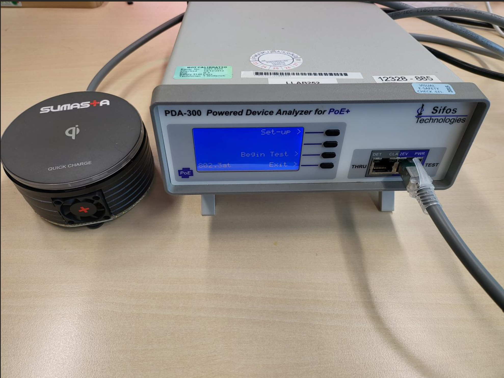
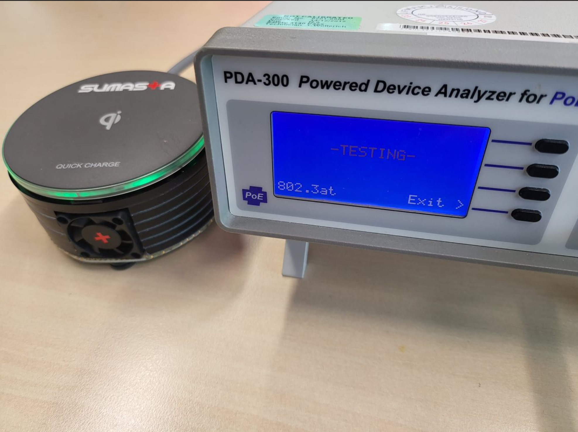
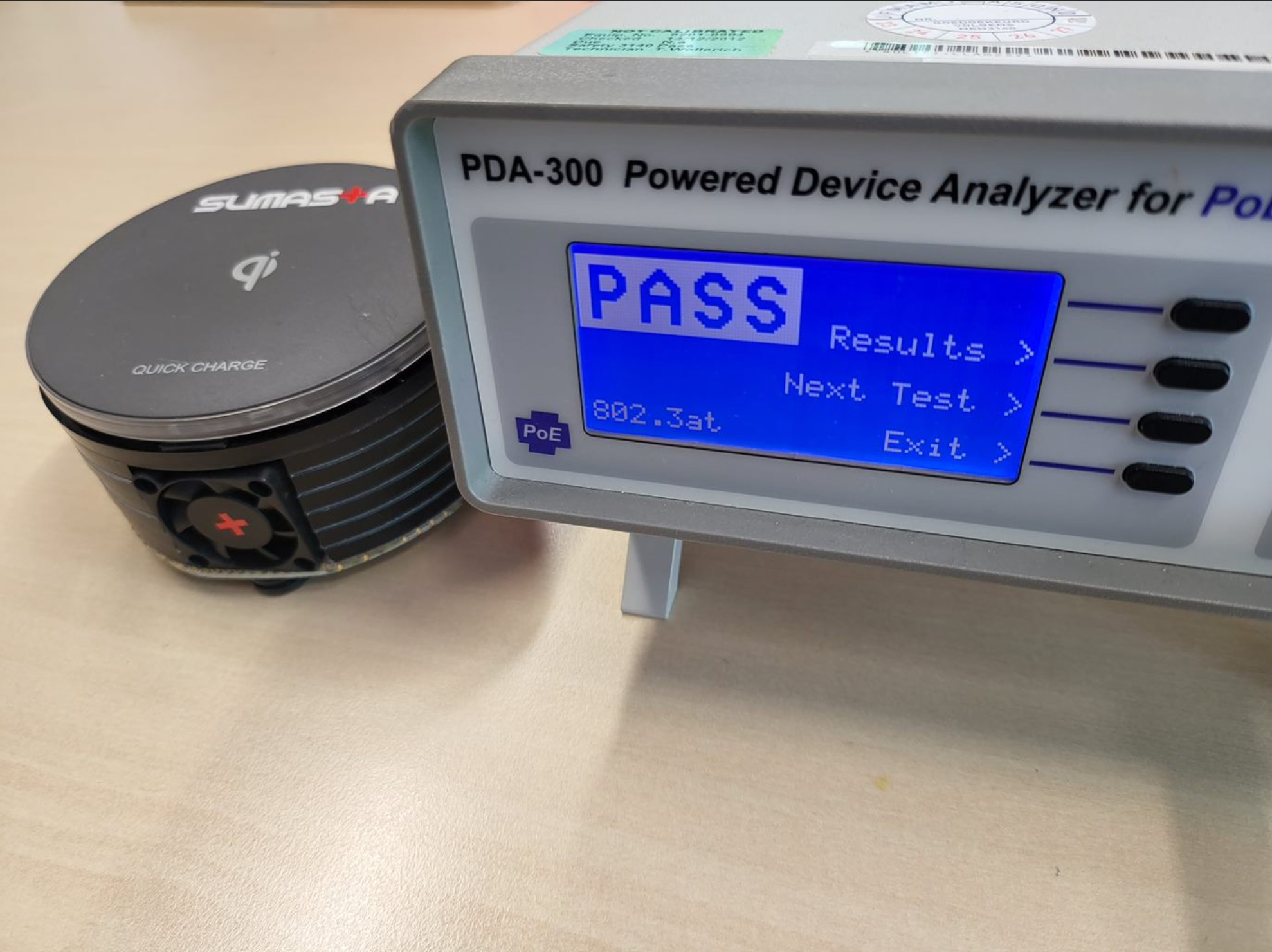
As I've worked, developed and commercially released PoE powered devices in the past, I have got access to dedicated PoE tester compliancy unit such as PDA-300 from Sifos as you can see below. Out of the box, I've decided to see and check whether Surf5 board in combination with WizPoE module in PoeQi unit complies with IEEE802af standard. It is purely an electrical check on making sure that it complies with all possible PoE configuration, injectors etc. The test was performed automatically in about 5 minutes and not only it tells you whether the unit passes the test, but also give you a nice extensive report. I'll attach the report in this build a well.
Good news, the PoeQi passed the test!
-
PoeQi Github Repo

-
PoE Compliancy Test Report

-
Housing Wall
-
Housing Cover
-
Diagram