
ESP32 (38-pin) + W5500: Offline LAN Relay Control with a Simple Web Server
ESP32와 WIZnet W5500를 SPI로 연결해, Wi-Fi/MQTT/클라우드 없이 로컬 LAN에서 웹페이지 ON/OFF 버튼으로 릴레이(GPIO25)를 제어하는 이더넷 기반 IoT 예제

WIZnet - W5500
x 1
Espressif - ESP32
x 1
ESP32(38-pin) + W5500로 Wi-Fi 없이 유선 LAN 릴레이 웹 제어하기 (오프라인 웹서버)
ESP32에 W5500를 SPI로 연결해 LAN 전용 웹서버를 만들고, 브라우저에서 ON/OFF 버튼으로 릴레이(GPIO25)를 제어합니다.
프로젝트 정보
- 카테고리: Ethernet / IoT / Web Server / Relay Control
- 네트워크: 유선 이더넷(LAN 전용)
- 인터페이스: SPI (ESP32 ↔ W5500)
- 제어 방식: HTTP 엔드포인트(
/on,/off) - 웹서버 포트: 80
- 제어 핀: GPIO 25 (릴레이)
구성품
- W5500 이더넷 모듈
- ESP32 38-pin 개발보드
- 릴레이 모듈
- 이더넷 케이블 + 공유기/스위치(LAN)
- USB/전원
소프트웨어 / 라이브러리
- Arduino IDE (ESP32)
- SPI
- EthernetESP32 라이브러리(예제 코드 기준)
1) 프로젝트 개요
이 프로젝트는 ESP32에 W5500 하드웨어 TCP/IP 이더넷 모듈을 연결해 Wi-Fi 없이 로컬 네트워크(LAN)에서만 동작하는 웹 기반 릴레이 제어를 구현합니다.
브라우저로 ESP32의 IP에 접속하면 ON/OFF 버튼이 있는 페이지가 뜨고, 버튼 클릭 시 /on, /off 요청으로 릴레이가 즉시 제어됩니다.
2) 왜 W5500 + Ethernet인가?
- Wi-Fi 대비 연결이 안정적이라 24/7 운용에 적합
- 로컬 네트워크에서 응답이 빠르고 지연이 낮음
- 외부 인터넷 없이 내부망(오프라인) 환경에서도 제어 가능
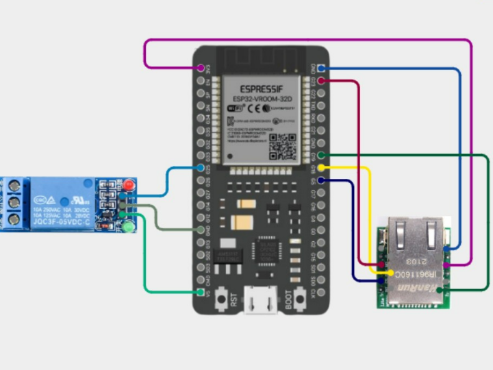
3) 배선 (SPI + 릴레이)
ESP32 ↔ W5500 (SPI 핀 정의 예시)
W5500_CS = 5W5500_SCK = 18W5500_MISO = 19W5500_MOSI = 23
Relay
- 릴레이 제어 핀: GPIO 25
- 로직:
HIGH → ON,LOW → OFF
보드/모듈에 따라 CS 핀 및 SPI 핀맵이 다를 수 있습니다. 사용하는 ESP32 보드 핀맵에 맞게 조정하세요.
4) 네트워크 설정 (고정 IP)
예제는 고정 IP(Static IP) 방식으로 구성되어 있어 업로드 후 브라우저에서 IP로 바로 접속합니다.
- MAC 예시:
DE:AD:BE:EF:32:01 - IP 예시:
192.168.1.210 - Gateway 예시:
192.168.1.1 - Subnet 예시:
255.255.255.0
접속 예:
http://192.168.1.210/
실제 공유기 대역이
192.168.0.x또는10.0.0.x라면 IP/Gateway를 그에 맞게 변경하세요.
5) 동작 방식
- ESP32가 SPI를 초기화하고 W5500 이더넷을 시작합니다.
- 포트 80에서 웹서버를 실행합니다.
- 브라우저 접속 시 ON/OFF 버튼이 있는 HTML 페이지를 제공합니다.
- 요청 URL을 파싱해 릴레이를 제어합니다.
GET /on→ 릴레이 ONGET /off→ 릴레이 OFF - 웹페이지에 현재 상태(ON/OFF)를 표시합니다.
6) 테스트 방법
- 스케치를 업로드합니다.
- 이더넷 케이블을 공유기/스위치에 연결합니다.
- 시리얼 모니터에서 설정된 IP를 확인합니다.
- 브라우저에서
http://<ESP32_IP>/로 접속합니다. - ON/OFF 버튼을 눌러 릴레이가 즉시 동작하는지 확인합니다.
7) 활용 아이디어
- 클라우드 없이 로컬 홈오토메이션(내부망 제어)
- 공장/현장 LAN 기반 릴레이 제어 패널
- 보안 요구가 높은 인트라넷 환경의 오프라인 IoT 스위칭
FAQ
Q1. 웹페이지가 열리지 않아요. 어디부터 확인하나요?
- ESP32와 W5500 전원이 정상인지 확인
- 이더넷 케이블 및 공유기/스위치 포트 상태 확인
- IP가 현재 네트워크 대역과 맞는지 확인(예: 192.168.1.x vs 192.168.0.x)
- 시리얼 모니터에서 이더넷 초기화/할당 IP 로그 확인
Q2. /on, /off는 정확히 뭘 의미하나요?
브라우저가 GET /on 또는 GET /off HTTP 요청을 보내면, ESP32가 해당 문자열을 감지해 릴레이 GPIO를 HIGH/LOW로 바꿉니다.
Q3. 고정 IP 대신 DHCP로도 가능한가요?
가능합니다. 다만 DHCP로 바꾸면 IP가 바뀔 수 있어, 접속 주소를 매번 확인해야 합니다. (고정 IP는 항상 같은 주소로 접속 가능)
Q4. 릴레이 핀(GPIO25)을 바꿀 수 있나요?
가능합니다. 사용 가능한 GPIO로 변경한 뒤 코드의 릴레이 핀 정의만 동일하게 맞추면 됩니다.
Q5. 릴레이가 반대로 동작해요(ON/OFF 뒤집힘).
릴레이 모듈이 Active LOW 타입일 수 있습니다. 이 경우 HIGH/LOW 로직을 반대로 적용하거나, 모듈 스펙에 맞게 제어 값을 조정하세요.
Offline LAN Relay Control with ESP32 (38-pin) + W5500 (Simple Web Server)
Connect W5500 to ESP32 via SPI to build a LAN-only web server, then control a relay (GPIO25) from a browser using ON/OFF buttons.
Project Info
- Category: Ethernet / IoT / Web Server / Relay Control
- Network: Wired Ethernet (LAN-only)
- Interface: SPI (ESP32 ↔ W5500)
- Control Method: HTTP endpoints (
/on,/off) - Web Server Port: 80
- Relay Pin: GPIO 25
Components
- W5500 Ethernet module
- ESP32 38-pin development board
- Relay module
- Ethernet cable + router/switch (LAN)
- USB / power supply
Software / Libraries
- Arduino IDE (ESP32)
- SPI
- EthernetESP32 library (as used in the example code)
1) Overview
This project shows how to use the W5500 hardware TCP/IP Ethernet module with an ESP32 to create an offline (LAN-only) web server.
Open the ESP32 IP address in a browser to see ON/OFF buttons. Clicking them sends /on and /off requests that immediately toggle a relay connected to GPIO25.
2) Why W5500 + Ethernet?
- More stable than Wi-Fi for 24/7 operation
- Low-latency response inside a local network
- Works without internet access (offline / intranet environments)
3) Wiring (SPI + Relay)
ESP32 ↔ W5500 (SPI pin definitions example)
W5500_CS = 5W5500_SCK = 18W5500_MISO = 19W5500_MOSI = 23
Relay
- Relay control pin: GPIO25
- Logic:
HIGH → ON,LOW → OFF
Pin mapping can vary by board/module. Adjust the SPI/CS pins to match your ESP32 board’s pinout.
4) Network Settings (Static IP)
The example uses a static IP so you can always access the device at the same address.
- MAC example:
DE:AD:BE:EF:32:01 - IP example:
192.168.1.210 - Gateway example:
192.168.1.1 - Subnet example:
255.255.255.0
Access:
http://192.168.1.210/
If your LAN uses
192.168.0.xor10.0.0.x, update the IP and gateway accordingly.
5) How It Works
- Initialize SPI and start W5500 Ethernet.
- Run a web server on port 80.
- Serve a simple HTML page with ON/OFF buttons.
- Parse the request URL and toggle the relay:
GET /on→ relay ONGET /off→ relay OFF - Display the current relay state (ON/OFF) on the page.
6) Testing
- Upload the sketch.
- Connect the Ethernet cable to a router/switch.
- Check the Serial Monitor for the configured IP.
- Open
http://<ESP32_IP>/in a browser. - Click ON/OFF and confirm the relay responds instantly.
7) Use Cases
- Local home automation without cloud access
- Industrial relay control panel over LAN
- Offline/intranet-only IoT switching for secure environments
FAQ
Q1. The web page doesn’t load. What should I check first?
- Confirm ESP32 and W5500 power is stable
- Check Ethernet cable and router/switch port status
- Make sure the static IP matches your LAN subnet (e.g., 192.168.1.x vs 192.168.0.x)
- Verify Ethernet initialization/IP output in the Serial Monitor
Q2. What do /on and /off actually do?
They are HTTP paths. When the browser sends GET /on or GET /off, the ESP32 detects the request string and sets the relay GPIO HIGH/LOW.
Q3. Can I use DHCP instead of a static IP?
Yes. With DHCP, the IP may change, so you’ll need to check the assigned address each time (static IP keeps access consistent).
Q4. Can I change the relay pin (GPIO25)?
Yes. Choose another suitable GPIO and update the relay pin definition in the code.
Q5. The relay works in reverse (ON/OFF swapped). Why?
Your relay module might be Active LOW. In that case, invert the logic (swap HIGH/LOW behavior) to match the module’s trigger type.