
STM32-based Ethernet-RS485 IoT gateway
STM32-based Ethernet-RS485 IoT gateway
이 프로젝트는 Ethernet–RS485 게이트웨이를 직접 설계하고 제작한 사례입니다. 글쓴이는 Mysensors 기반 스마트홈 환경에서 RS-485 노드를 중앙 컨트롤러로 연결하기 위한 유선 게이트웨이를 만들기 위해 자체 PCB를 설계했고, 그 결과물을 공유했습니다.
설계 목표 및 배경
작성자는 기존에 Jumper 와이어, 브레드보드로 회로를 구성하는 데 한계를 느껴 직접 PCB 제작을 결심했습니다. 초기에 회로 설계 → PCB 레이아웃 → JLCPCB에서 제작 주문까지 직접 진행했습니다.
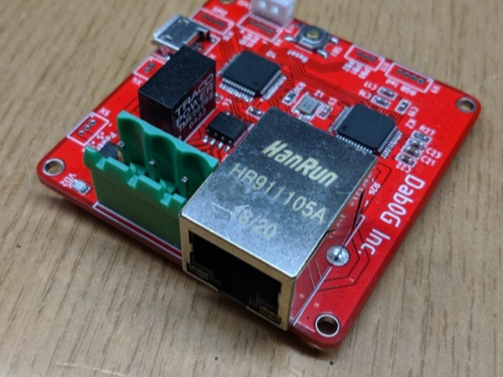
핵심 구성 요소
시스템의 핵심은 아래 부품들입니다.
- STM32F103CBT6: 게이트웨이의 메인 MCU. Cortex-M3 기반, 128 KB Flash, 20 KB RAM, 72 MHz 동작.
- WIZnet W5500: SPI 기반 Ethernet 컨트롤러로, 하드웨어 TCP/IP 스택을 내장하고 최대 8개의 TCP/UDP 소켓을 지원합니다.
- MAX13488EESA+T: RS-485 드라이버. 속도 최대 16 Mb/s, 자동 송수신 방향 전환 기능을 갖고 있어 UART에 직접 연결 가능합니다.
MCU는 3.3 V로 구동되고, 8 MHz 및 32.768 kHz 크리스탈을 필요로 합니다. 디버깅과 프로그래밍용 SWD 인터페이스가 제공됩니다.
이더넷 인터페이스

Ethernet 측에는 W5500을 사용합니다. 작성자는 W5500 내부에 Cortex-M0 기반 코어가 포함되어 있다고 언급하고 있으나, 실제로 W5500은 범용 MCU 코어를 포함하지 않는 하드웨어 TCP/IP Ethernet 컨트롤러입니다. 이 칩은 SPI 인터페이스를 통해 MCU와 연결되며 3.3 V 전원에서 동작합니다. 하드웨어적으로 TCP, UDP, MAC, ICMP, ARP, IGMP, PPPoE 등을 처리하고 32 KB 버퍼를 제공, 최대 8개의 독립적인 소켓을 지원합니다.
링크 속도 100 Mbps에서 약 132 mA의 소비 전류가 발생하며 Wake-on-LAN 기능과 통신 상태 표시용 LED를 제어할 수 있는 핀도 제공합니다.
RS-485 측 설계
게이트웨이의 이동성 인터페이스는 RS-485입니다. 글쓴이는 MAX13488EESA+T를 RS-485 드라이버로 선택했으며, 해당 드라이버는 송·수신 방향 전환을 자동으로 처리할 수 있어 MCU에서 DE/RE 신호를 따로 제어할 필요가 없습니다.
해당 드라이버는 5 V 전원 조건에서 동작하고, 최대 128개의 노드를 하나의 RS-485 라인에 연결할 수 있습니다.
절연 설계
작성자는 신뢰성과 안전성을 위해 전기적 절연을 설계에 포함했습니다. RS-485 라인과 게이트웨이 간 갈바닉 절연을 위해 Texas Instruments의 디지털 절연기 ISO7321CDR을 사용하고, 전원 절연은 Traco Power TME0505S DC/DC를 적용했습니다.
이 절연은 RS-485 버스와 메인 회로 사이의 접지 전위차, 외부 잡음, 서지로 인한 오동작을 억제하기 위한 것입니다.
회로 및 PCB 설계
회로는 세 부분으로 나뉘어 있습니다: RS-485, MCU 주변부, Ethernet.
- RS-485 부분: MAX13488 및 절연 회로

- MCU 부분: STM32와 전원, 크리스탈, 디버그 포트

- Ethernet 부분: W5500 및 RJ45 모듈

PCB 사이즈는 약 50×50 mm로 설계되었으며, SMT 부품 대부분을 0603 규격으로 선택했습니다. STM32와 W5500은 제조사 권장 레이아웃으로 배치되어 있습니다.

전원은 5 V 입력을 받고, 3.3 V는 LDO 레귤레이터(LDL1117S33R)로 생성됩니다. 이 5 V는 RS-485 드라이버와 절연부, DC/DC 등에 사용됩니다.
구축 결과 및 사용자 경험

사용자는 초기 회로에서 RS-485 라인의 종단 저항과 풀업/풀다운 저항이 부족해 통신 문제를 겪었고, 이 문제는 종단 저항과 적절한 풀업 저항 추가로 해결했습니다.

완성된 게이트웨이는 수개월 동안 오류 없이 작동했으며, 글쓴이는 해당 설계를 compact, 고속, 안정적인 Ethernet-RS485 게이트웨이로 설명합니다.
정리
- 적용 환경
RS-485 기반 센서·액추에이터를 Ethernet 네트워크로 연결해야 하는 환경을 전제로 하며, Mysensors 기반 스마트홈이 실제 적용 사례로 제시됨. 스마트홈, 소형 빌딩 자동화, 실험실 설비, 테스트·검증 장비 등 유선 통신 안정성이 요구되는 영역에 적합함. - 적용 규모
수 개에서 수십 개 수준의 RS-485 노드를 하나의 게이트웨이에 수용하는 소규모~중간 규모 시스템에 적합하며, 대규모 산업 제어 시스템을 목표로 하지는 않음. - 반복 적용 및 양산 가능성
STM32F103, W5500, MAX13488 등 범용 부품을 사용하고 50×50 mm 소형 PCB와 0603 패키지를 채택해 단발성 데모가 아닌 반복 제작과 소량 양산을 염두에 둔 구조임. - 대상 사용자
완성품 소비자보다는 개발자, 소규모 시스템 통합 업체, ODM/OEM 초기 단계에서 기술 검증을 수행하는 사용자를 주요 대상으로 함. - WIZnet 활용 관점
Ethernet 통신을 WIZnet W5500에 전적으로 의존하는 구조로, MCU 부담을 줄이면서 안정적인 네트워크 연결을 제공하며 동일한 Ethernet 구조를 다른 필드 인터페이스와 결합해 반복적으로 활용 가능한 WIZnet 기반 적용 사례로 평가 가능함.
FAQ
Q1. 이 게이트웨이는 어떤 환경에서 사용하기에 적합한가요?
A. RS-485 기반 센서나 액추에이터를 Ethernet 네트워크에 연결해야 하는 환경에 적합하며, 스마트홈, 소형 빌딩 자동화, 실험실 설비, 테스트·검증 장비 등 유선 통신의 안정성이 요구되는 소규모~중간 규모 시스템을 주요 대상으로 합니다.
Q2. 이 프로젝트는 단발성 데모인가요, 반복 적용이 가능한 구조인가요?
A. 범용 부품(STM32F103, W5500, MAX13488)을 사용하고 소형 PCB와 표준 패키지를 채택해 단발성 데모보드가 아닌 반복 제작과 소량 양산을 고려한 구조로 설계되었습니다.
Q3. Ethernet 통신을 MCU에서 직접 처리하지 않은 이유는 무엇인가요?
A. WIZnet W5500의 하드웨어 TCP/IP 기능을 활용해 MCU 부하를 줄이고, 펌웨어 복잡도를 낮추며, 안정적인 네트워크 통신을 확보하기 위함입니다.
Q4. RS-485 통신에서 송수신 제어는 어떻게 처리되나요?
A. MAX13488EESA+T 드라이버의 자동 송·수신 방향 전환 기능을 사용해, MCU에서 DE/RE 신호를 직접 제어하지 않아도 UART 기반 RS-485 통신이 가능합니다.
Q5. 이 설계의 주요 대상 사용자는 누구인가요?
A. 완성품 소비자보다는 하드웨어와 펌웨어를 직접 제어할 수 있는 개발자, 소규모 시스템 통합 업체, ODM/OEM 초기 개발 단계에서 기술 검증을 수행하는 사용자를 주요 대상으로 합니다.
This project presents the design and implementation of an Ethernet–RS485 gateway. The author developed the gateway to connect RS-485 nodes to a central controller in a Mysensors-based smart home environment, designing a custom PCB and sharing the final result.
Design Goals and Background
The author identified limitations in building circuits using jumper wires and breadboards, particularly in terms of reliability and repeatability, and therefore decided to design a dedicated PCB. The entire process—from schematic design to PCB layout and manufacturing—was carried out directly, with the goal of creating hardware suitable for real use rather than temporary experimentation.
Key Components
The system is built around the following core components:
- STM32F103CBT6: The main MCU of the gateway. It is based on an ARM Cortex-M3 core, operates at up to 72 MHz, and provides 128 KB of Flash and 20 KB of RAM.
- WIZnet W5500: An SPI-based Ethernet controller with a built-in hardware TCP/IP stack, supporting up to eight simultaneous TCP/UDP sockets.
- MAX13488EESA+T: An RS-485 transceiver supporting data rates up to 16 Mb/s and featuring automatic transmit/receive direction control, allowing direct connection to a UART.
The MCU operates at 3.3 V and requires 8 MHz and 32.768 kHz crystals. An SWD interface is provided for debugging and firmware programming.
Ethernet Interface
The Ethernet interface is implemented using the W5500. Although the original author mentions the presence of a Cortex-M0-based core inside the W5500, in practice the W5500 is a hardware TCP/IP Ethernet controller without a general-purpose MCU core. It connects to the MCU via SPI and operates from a 3.3 V supply. The chip handles TCP, UDP, MAC, ICMP, ARP, IGMP, and PPPoE protocols in hardware, provides a 32 KB internal buffer, and supports up to eight independent sockets.
At a 100 Mbps link speed, the device consumes approximately 132 mA and provides pins for Wake-on-LAN functionality and Ethernet status LEDs.
RS-485 Interface Design
The gateway’s field interface is RS-485. The author selected the MAX13488EESA+T as the RS-485 driver, which automatically manages transmit and receive direction switching, eliminating the need for explicit DE/RE control by the MCU.
The driver operates from a 5 V supply and allows up to 128 nodes to be connected on a single RS-485 bus.
Isolation Design
To improve reliability and safety, electrical isolation was included in the design. Galvanic isolation between the RS-485 bus and the gateway is implemented using a Texas Instruments digital isolator, ISO7321CDR, while power isolation is provided by a Traco Power TME0505S isolated DC/DC converter.
This isolation scheme mitigates issues caused by ground potential differences, external noise, and surge events between the RS-485 network and the main system circuitry.
Circuit and PCB Design
The circuit is divided into three functional areas: the RS-485 section, the MCU section, and the Ethernet section.
- RS-485 section: MAX13488 and isolation circuitry
- MCU section: STM32, power regulation, crystals, and debug interface
- Ethernet section: W5500 and RJ45 connector
The PCB measures approximately 50 × 50 mm, and most passive components use 0603 packages. Both the STM32 and W5500 are placed according to the manufacturers’ recommended layout guidelines.
The board is powered from a 5 V input. A 3.3 V rail is generated using an LDO regulator, and the 5 V rail is also used for the RS-485 driver, isolation circuitry, and the DC/DC converter.
Implementation Results and User Experience
During initial testing, communication issues were observed due to insufficient termination and pull-up/pull-down resistors on the RS-485 line. After adding proper termination and biasing, the system operated reliably.
The completed gateway ran for several months without errors and was described by the author as a compact, high-speed, and stable Ethernet–RS485 gateway.
Deployment Context, Target Users, and Scalability Assessment
- Deployment Environment
The design targets environments where RS-485-based sensors and actuators must be connected to an Ethernet network. Typical use cases include smart homes, small building automation systems, laboratory setups, and test or validation equipment where reliable wired communication is required. - System Scale
The gateway is suitable for small to medium-scale systems, supporting several to several dozen RS-485 nodes per gateway, rather than large industrial control installations. - Repeatability and Production Potential
The use of widely available components and a compact PCB form factor makes the design suitable not only for one-off prototypes but also for repeated deployment and small-scale production. - Target Users
The design is intended for developers, small system integrators, and ODM/OEM teams in early development or technology validation stages, rather than end-user consumer products. - WIZnet Usage Perspective
Ethernet connectivity relies entirely on the WIZnet W5500, reducing MCU load while providing stable network communication. The same Ethernet architecture can be reused with different field interfaces, making this a representative example of a reusable WIZnet-based Ethernet gateway design.