
RP2040で動作するModbusTCPSlave(改良)
An Ethernet-based embedded node with time display and integrated I/O
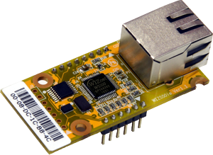
WIZnet - WIZ550io
x 1
이 프로젝트는 RP2040 마이크로컨트롤러에서 동작하는 Modbus TCP Slave 장치를 구현하고, 실제 시스템에서 활용 가능한 수준으로 기능을 확장하기 위한 개선 버전입니다.
기존 구현은 Modbus 통신 자체는 정상적으로 동작했지만 다음과 같은 보완 필요성이 확인되었습니다.
- 시스템 상태를 확인할 수 있는 표시 장치 부재
- 입출력 인터페이스 구조 정리 필요
- Ethernet NIC 제어 핀 재배치 필요
- 타이머 기반 동작 관리 필요
- Watchdog 기반 안정성 검토
이를 해결하기 위해 다음과 같은 기능이 추가되었습니다.
- NTP 기반 시간 동기화
- TM1637 4자리 7세그 표시기 시간 표시
- 디지털 출력 및 버튼 입력 인터페이스
- 아날로그 입력 채널 추가
- Timer Interrupt 기반 주기 제어
- Watchdog 기반 시스템 안정성 관리
결과적으로 이 장치는 단순한 Modbus 통신 데모를 넘어 Ethernet 기반 소형 I/O 제어 노드 형태로 발전하게 됩니다.
시스템 아키텍처
전체 시스템은 RP2040 MCU와 W5500 Ethernet 컨트롤러를 중심으로 구성됩니다. W5500이 TCP/IP 스택을 하드웨어에서 처리하며, RP2040은 Modbus 프로토콜 처리와 장치 제어 로직을 담당합니다.
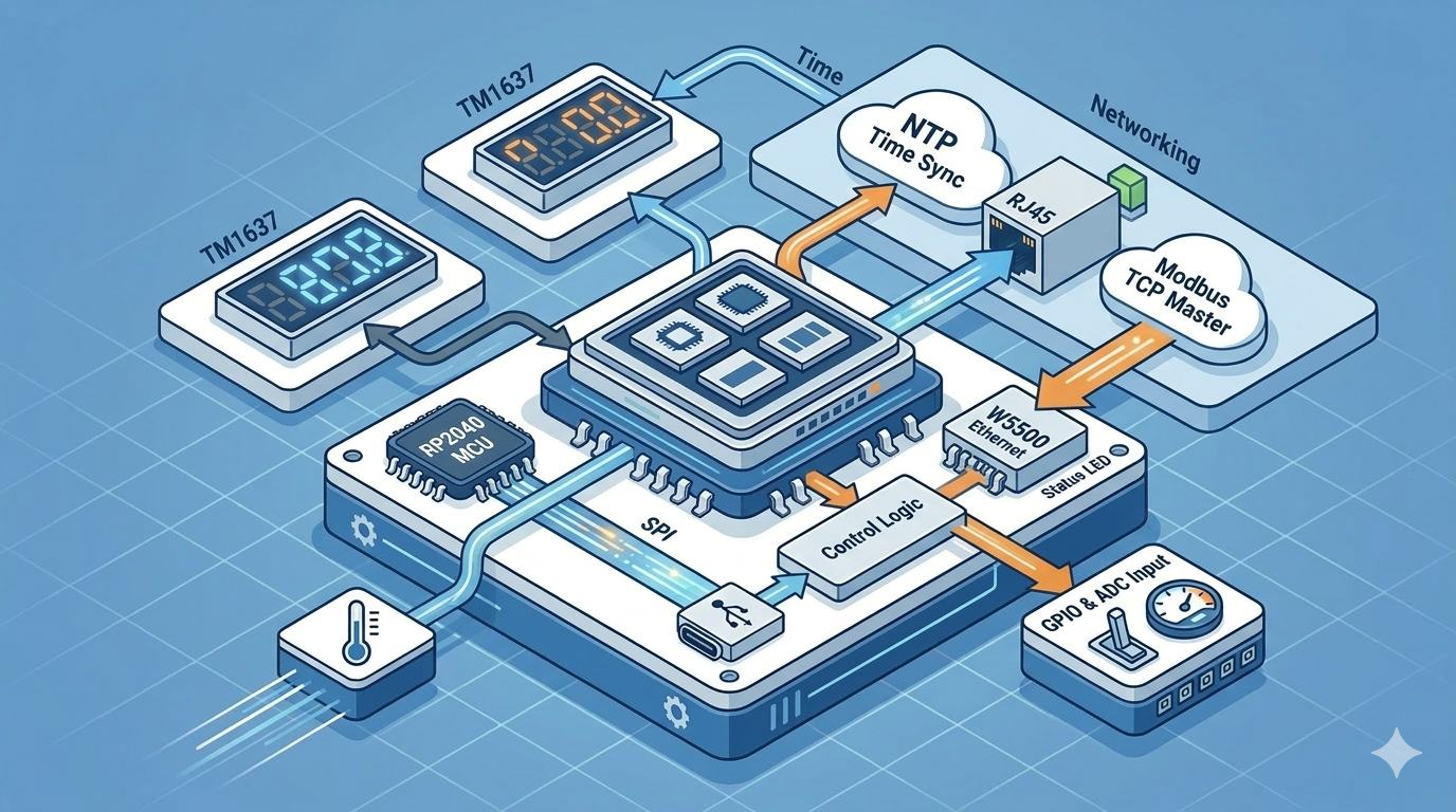
시스템 동작 흐름은 다음과 같습니다.
- 전원 인가
- SPI 인터페이스 및 W5500 초기화
- 고정 IP 기반 Ethernet 연결 설정
- NTP 서버에서 현재 시간 동기화
- TM1637 표시기에 시각 표시
- Modbus TCP Slave 서비스 시작
- Modbus Master 요청 처리
- GPIO 및 ADC 데이터 갱신
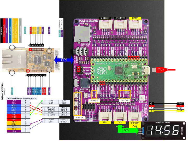
하드웨어 구성
본 시스템은 다음과 같은 하드웨어로 구성됩니다.
핵심 구성
- MCU : RP2040
- Ethernet Controller : W5500
- Ethernet Board : W5500-EVB-Pico
- Development Board : MakerPi Pico
표시 장치
- TM1637 기반 4자리 7-Segment Display
디지털 출력
- GP16
- GP17
Modbus Coil을 통해 제어되며 LED 상태로 출력됩니다.
디지털 입력
- GP20
- GP21
- GP22
Push Button 입력으로 사용됩니다.
아날로그 입력
- GP26
- GP27
- GP28
센서 입력 또는 전압 모니터링에 사용할 수 있습니다.
주의 사항:
- ADC 입력은 3.3V 이하만 허용됩니다.
- ADC_Vref 핀에 기준 전압을 설정하면 측정 정확도를 개선할 수 있습니다.
Grove 인터페이스 구성
확장성을 위해 Grove 포트 역할이 다음과 같이 정의되었습니다.
| Grove Port | 기능 |
|---|---|
| GROVE1 | UART |
| GROVE2 | 사용 금지 (NIC 사용) |
| GROVE3 | 사용 금지 (NIC 사용) |
| GROVE4 | I2C |
| GROVE5 | DIO (표시기 연결) |
| GROVE6 | Analog Input |
이러한 구조는 Ethernet 인터페이스와 충돌을 방지하면서 향후 센서 확장을 고려한 설계입니다.
Modbus 메모리 맵 구조
Modbus 프로토콜을 일반적인 산업용 장치와 동일한 방식으로 구성하기 위해 4개의 메모리 블록을 분리하여 관리합니다.
| 메모리 영역 | 역할 |
|---|---|
| Coil | 디지털 출력 |
| Discrete Input | 디지털 입력 |
| Holding Register | 제어 레지스터 |
| Input Register | 센서 데이터 |
지원 Function Code
- FC1 : Read Coils
- FC2 : Read Discrete Inputs
- FC3 : Read Holding Registers
- FC4 : Read Input Registers
- FC5 : Write Single Coil
- FC6 : Write Single Register
- FC15 : Write Multiple Coils
- FC16 : Write Multiple Registers
예를 들어 Modbus Master가 Coil[0]을 ON으로 설정하면 GP16에 연결된 LED 상태가 변경됩니다.
시간 동기화와 7-세그 표시
장치는 NTP 서버를 이용하여 네트워크에서 현재 시간을 받아옵니다.
설정 예시
- NTP Server : 192.168.0.199
- Slave IP : 192.168.0.208
시간 동기화가 완료되면 다음 기능이 동작합니다.
- TM1637 4자리 디스플레이에 시/분 표시
- 콜론 표시 1초 주기 점멸
- RP2040 내장 LED 동기 점멸
이 기능은 장치의 동작 상태와 네트워크 연결 상태를 직관적으로 확인할 수 있도록 합니다.
커스텀 MgsModbus 라이브러리
이 프로젝트에서는 기존 Arduino 기반 MgsModbus 라이브러리를 수정하여 사용합니다.
수정 목적은 다음과 같습니다.
- Slave 기능 중심으로 단순화
- Modbus 메모리 블록 분리
- 일반적인 Modbus 장치 구조에 맞는 주소 처리
W5500 안정 동작을 위한 Ethernet3 라이브러리 사용
라이브러리 내부에서는 Modbus 요청 프레임을 직접 분석하여 Function Code에 따라 응답을 생성합니다.
이 구조 덕분에 RP2040에서도 비교적 단순한 코드로 Modbus TCP Slave를 구현할 수 있습니다.
WIZnet Insight
이 프로젝트에서 중요한 역할을 하는 구성 요소는 W5500 Ethernet 컨트롤러입니다.
W5500은 TCP/IP 프로토콜 스택을 하드웨어로 처리하는 Hardwired TCP/IP 구조를 사용합니다. 이 방식은 MCU가 네트워크 프로토콜의 복잡한 처리 과정을 수행할 필요가 없도록 해줍니다.
이러한 구조 덕분에 RP2040은 다음과 같은 작업에 집중할 수 있습니다.
- Modbus 프로토콜 처리
- GPIO 및 센서 데이터 처리
- 표시 장치 제어
- 시스템 관리 로직
결과적으로 저가 MCU 환경에서도 안정적인 Ethernet 기반 산업 프로토콜 장치를 구현할 수 있습니다. W5500-EVB-Pico와 같은 평가 보드는 이러한 설계를 빠르게 검증할 수 있는 좋은 플랫폼이 됩니다.
활용 가능 시나리오
이 구조는 다양한 산업 및 IoT 환경에서 활용될 수 있습니다.
원격 I/O 장치
Modbus TCP를 사용하는 PLC 시스템에서 디지털 I/O 확장 장치로 사용
설비 상태 모니터링
센서 값을 Input Register로 제공하여 SCADA 시스템에서 모니터링
네트워크 기반 제어 노드
소형 설비나 테스트 장비를 Ethernet으로 제어
교육 및 연구 플랫폼
Ethernet 기반 산업 프로토콜 학습 및 테스트용 개발 플랫폼
향후 개선 과제
현재 프로젝트는 기능적으로 동작하지만 다음과 같은 개선 여지가 존재합니다.
- Watchdog 재시작 검증 방법 확립
- 일부 Modbus 메모리 처리 로직 검토
- W5500-EVB-Pico 중심 하드웨어 재구성
- 코드 구조 정리 및 모듈화
이러한 개선이 진행된다면 보다 안정적인 Modbus TCP 노드로 발전할 수 있습니다.
FAQ
Q1. 이 프로젝트는 어떤 Modbus 기능을 지원합니까?
Read/Write Coil, Discrete Input, Holding Register, Input Register 등 주요 Modbus TCP 기능을 지원합니다.
Q2. W5500을 사용하는 이유는 무엇입니까?
W5500은 TCP/IP 프로토콜을 하드웨어에서 처리하기 때문에 MCU의 부담을 크게 줄여주고 안정적인 Ethernet 통신을 제공합니다.
Q3. NTP 기능은 왜 필요한가요?
장치 내부 시간 정보를 표시하거나 로그 기록 등에 사용할 수 있기 때문입니다.
Q4. 이 장치는 산업 현장에서 바로 사용할 수 있습니까?
기본 구조는 산업용 Modbus 장치와 동일하지만, 장기간 안정성 검증과 하드웨어 보호 설계가 추가로 필요합니다.
Q5. RP2040 대신 다른 MCU에서도 사용할 수 있습니까?
가능합니다. 다만 SPI 인터페이스와 Ethernet 라이브러리를 MCU 환경에 맞게 수정해야 합니다.
The goal of this project is to implement a Modbus TCP Slave device on the RP2040 and extend it beyond a simple communication example into a more practical embedded system.
Although the earlier implementation worked correctly as a Modbus Slave, several improvements were required:
- Lack of a visual status indicator
- Limited I/O structure
- Need for Ethernet NIC pin reconfiguration
- Absence of timer-driven system behavior
- Need for watchdog-based reliability testing
To address these issues, the following features were added:
- NTP-based time synchronization
- TM1637 4-digit clock display
- Digital output and button input interface
- Analog input channels
- Timer interrupt for periodic tasks
- Watchdog monitoring
As a result, the system evolves from a basic communication demo into a compact Ethernet-based remote I/O node.
System Architecture
The system is built around an RP2040 MCU and a W5500 Ethernet controller.
The W5500 handles the TCP/IP protocol stack in hardware, while the RP2040 manages Modbus logic and device control.
The system startup sequence is as follows:
- Power is applied
- SPI interface and W5500 Ethernet controller are initialized
- Ethernet network parameters are configured using a static IP
- The system requests the current time from an NTP server
- Time is stored in the internal clock
- The TM1637 display shows the current time
- The Modbus TCP Slave server starts
- Modbus requests from the master device are processed
Hardware Configuration
The system consists of the following hardware components.
Core Components
- MCU: RP2040
- Ethernet Controller: W5500
- Ethernet Board: W5500-EVB-Pico
- Base Board: MakerPi Pico
Display Device
- TM1637 4-digit 7-segment display
Digital Outputs
- GP16
- GP17
These outputs are controlled through Modbus Coil registers and typically drive LEDs.
Digital Inputs
- GP20
- GP21
- GP22
These pins are connected to push-button switches and exposed as Discrete Inputs in the Modbus memory map.
Analog Inputs
- GP26
- GP27
- GP28
These inputs can monitor sensor voltages or analog signals.
Important notes:
Input voltage must not exceed 3.3V.
ADC accuracy can be improved by setting a reference voltage on the ADC_Vref pin.
Grove Interface Configuration
To improve expandability, the Grove connectors are assigned as follows:
| Grove Port | Function |
|---|---|
| GROVE1 | UART |
| GROVE2 | Disabled (used by NIC) |
| GROVE3 | Disabled (used by NIC) |
| GROVE4 | I2C |
| GROVE5 | Digital I/O (Display connection) |
| GROVE6 | Analog Input |
This configuration avoids conflicts with the Ethernet interface while preserving flexibility for sensor expansion.
Modbus Memory Map Design
The Modbus memory model is implemented using four separate data blocks to match standard industrial Modbus devices.
| Memory Area | Purpose |
|---|---|
| Coil | Digital outputs |
| Discrete Input | Digital inputs |
| Holding Register | Control registers |
| Input Register | Sensor data |
Supported Modbus Function Codes
- FC1 – Read Coils
- FC2 – Read Discrete Inputs
- FC3 – Read Holding Registers
- FC4 – Read Input Registers
- FC5 – Write Single Coil
- FC6 – Write Single Register
- FC15 – Write Multiple Coils
- FC16 – Write Multiple Registers
For example, when the Modbus master writes Coil[0] = ON, the LED connected to GP16 turns off (active-low configuration).
Time Synchronization and 7-Segment Display
The system synchronizes its internal clock using an NTP server.
Example configuration:
- NTP Server: 192.168.0.199
- Slave Device IP: 192.168.0.208
After synchronization:
- The TM1637 display shows the current hour and minute
- The colon indicator blinks once per second
- The built-in LED on GP25 blinks in sync with the clock update
This feature provides a simple visual confirmation that the device is operating normally.
Custom MgsModbus Library
This project uses a modified version of the MgsModbus library originally developed for Arduino.
Several modifications were applied:
- Removal of unnecessary Modbus master features
- Separation of Modbus memory blocks
- Address mapping adjustments to resemble standard Modbus devices
- Adoption of the Ethernet3 library for better compatibility with W5500
The library directly parses Modbus request frames and generates appropriate responses based on the function code.
This lightweight implementation makes it feasible to run a full Modbus TCP Slave on the RP2040.
WIZnet Insight
A key component of this design is the W5500 Ethernet controller.
The W5500 implements a hardwired TCP/IP stack, meaning that complex networking tasks such as:
- TCP session handling
- packet buffering
- checksum processing
- are handled entirely in hardware.
This architecture significantly reduces the processing burden on the MCU.
As a result, the RP2040 can dedicate most of its resources to:
- Modbus protocol handling
- sensor processing
- I/O control
- application logic
Using the W5500-EVB-Pico evaluation board, developers can quickly prototype reliable Ethernet devices without implementing a full software TCP/IP stack.
Practical Application Scenarios
This architecture can be used in various industrial and IoT applications.
Remote I/O Device
Expand PLC systems with additional Ethernet-based digital and analog I/O.
Equipment Monitoring
Provide sensor values via Modbus Input Registers to SCADA systems.
Network-Controlled Devices
Control small machines or test equipment through Ethernet.
Educational Platform
A useful platform for learning industrial Ethernet protocols and embedded networking.
Future Improvements
Although the system operates correctly, several areas require further investigation.
- Verification of watchdog-triggered system resets
- Review of certain Modbus memory handling logic
- Hardware optimization for W5500-EVB-Pico integration
- Code modularization and refactoring
With these improvements, the project could evolve into a more robust industrial Ethernet node.
FAQ
What Modbus functions are supported?
The implementation supports the major Modbus TCP functions including reading and writing coils, discrete inputs, holding registers, and input registers.
Why is the W5500 used instead of a software TCP/IP stack?
The W5500 handles the TCP/IP stack in hardware, which reduces firmware complexity and improves reliability.
Why does the system use NTP time synchronization?
Time synchronization allows the device to display accurate time and can be useful for logging or monitoring applications.
Can this system be deployed directly in industrial environments?
The architecture is suitable, but additional hardware protection and long-term reliability testing would be required for production use.
Can this project run on other microcontrollers?
Yes. However, the SPI interface and Ethernet libraries would need to be adapted for the target platform.