


ModBus to MQTT Ethernet Bridge for a Solis 1.5kW Inverter
No Wi-Fi in the Shed, Two Months Without a Reset — A Solis Inverter Modbus-to-MQTT Bridge Built on ATmega32U4 and W5500
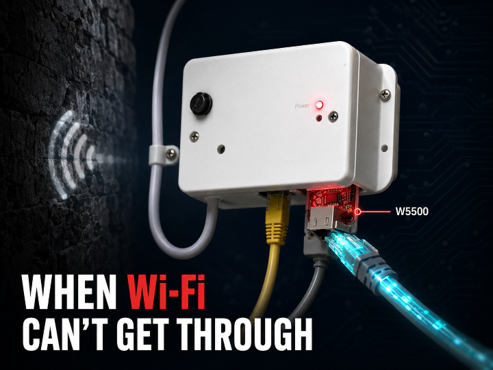

WIZnet - W5500
x 1

요약
영국의 메이커 Brian Dorey는 석조 벽에 가로막혀 Wi-Fi가 끊기던 태양광 인버터 로거를 ATmega32U4 + W5500 유선 이더넷 브리지로 교체했습니다. 인버터의 Modbus RTU 데이터를 읽어 로컬 MQTT 브로커로 발행하고 Home Assistant에 연결하는 구조로, 제조사 클라우드를 전혀 경유하지 않습니다. 주목할 점은 이 장치의 MCU가 SRAM 2.5KB짜리 8비트 AVR이라는 사실이며, 그럼에도 이더넷이 성립한 이유는 TCP/IP가 소프트웨어가 아니라 칩 안에 있기 때문입니다.
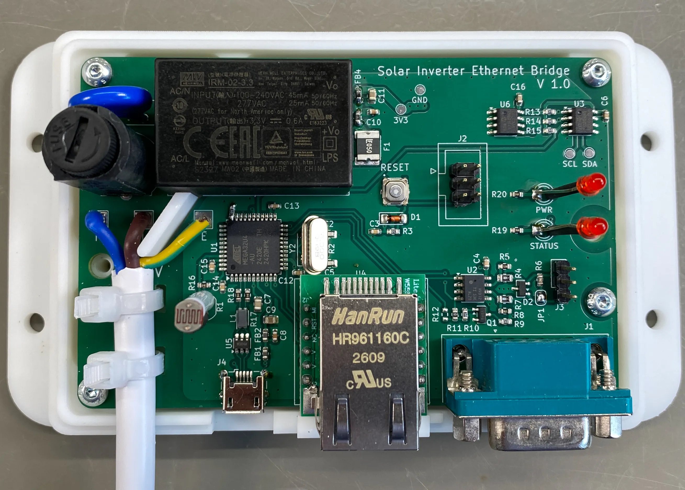
개요
가정용 태양광 인버터는 대부분 제조사가 제공하는 Wi-Fi 데이터로거 스틱을 통해 클라우드로 데이터를 보냅니다. 편리하지만 두 가지 대가가 따릅니다. 데이터가 내 손을 떠난다는 점, 그리고 무선 링크가 끊기면 계측도 함께 멈춘다는 점입니다.
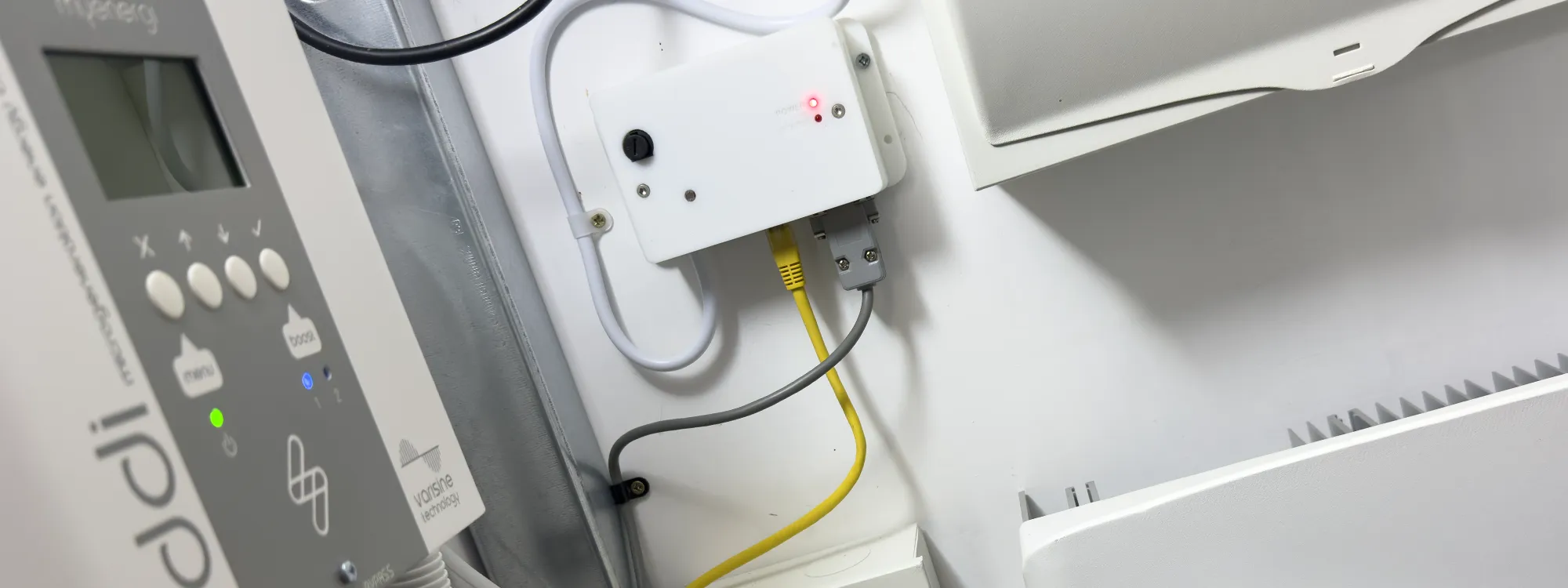
이 프로젝트의 인버터는 주택에서 떨어진 창고(shed)에 설치돼 있고, 라우터와의 사이에는 2미터가 넘는 석재와 콘크리트가 놓여 있습니다. 저자가 앞서 만든 ESP32 기반 Wi-Fi 브리지는 이 벽 앞에서 접속 실패와 프리즈를 반복했습니다. 안테나를 바꾸거나 재접속 로직을 다듬어 해결할 수 있는 문제가 아니었습니다.
그래서 선택한 답이 유선화입니다. 다만 조건이 하나 붙었습니다. Raspberry Pi 시절의 소비전력(2~5W)으로 되돌아가지 않을 것. 이 글은 그 두 조건을 동시에 만족시키기 위해 8비트 MCU에 하드와이어드 TCP/IP 칩을 붙인 설계를 다룹니다.
원문: https://www.briandorey.com/post/solis-inverter-rs485-ethernet-bridge
같은 문제를 세 번 푼 기록
이 브리지는 갑자기 등장한 설계가 아닙니다. 저자는 4년에 걸쳐 같은 문제를 세 번 다시 풀었습니다.
| 구분 | 1세대 (2022-05) | 2세대 (2022-10) | 3세대 (2026-08) |
|---|---|---|---|
| 연산 플랫폼 | Raspberry Pi 3 | ESP32-WROOM-32U | ATmega32U4 (8비트 AVR) |
| RS-485 | RS485 Pi 보드 | SN65HVD72D | SN65HVD72D |
| 네트워크 | Pi 내장 | Wi-Fi (외장 안테나) | W5500 유선 이더넷 |
| 소프트웨어 | Python 3 + minimalmodbus + paho.mqtt | ESP32 펌웨어 (C) | 베어메탈 C (XC8) |
| 소비전력 | 2~5W | 0.2~0.5W | 미측정 |
| 탈락 사유 | 소비전력 과다 | 석조 격벽에서 접속 실패 | 현행 (2개월 무정지) |
세대가 바뀔수록 연산 플랫폼은 계속 가벼워졌습니다. Linux가 돌던 SoC에서 시작해 마지막에는 SRAM 2.5KB의 8비트 마이크로컨트롤러까지 내려왔습니다. 그런데 이 흐름에서 정확히 하나의 계층만 반대 방향으로 움직였습니다. TCP/IP입니다. 1세대에서는 리눅스 커널이, 2세대에서는 ESP-IDF의 소프트웨어 스택이 처리하던 일이, 3세대에서는 별도 실리콘으로 옮겨갔습니다.
세대별 탈락 사유가 서로 다르다는 점도 짚어둘 만합니다. 1세대는 전력, 2세대는 물리 환경이 원인이었습니다. 두 문제 모두 소프트웨어 최적화로는 풀 수 없는 종류였고, 그래서 매번 하드웨어 구성 자체가 바뀌었습니다.
여담이지만 3세대의 RS-485 바이어싱 저항 구성은 1세대의 유산입니다. 당시 인버터와 통신이 전혀 되지 않자 저자는 제조사 Wi-Fi 로거를 현미경으로 뜯어보고 A/B 라인의 풀업·풀다운 저항 구성을 역설계해 문제를 풀었습니다.
1세대 원문: https://www.briandorey.com/post/solar-upgrade-solis-1-5kw-inverter-raspberry-pi-rs485-logging
도입 배경 — 왜 인버터를 로컬로 끌어내리는가
저장소 도입 사례: 확인 불가. GitHub 저장소는 Star·Fork·Watcher가 모두 0이며 MIT 라이선스로 공개된 개인 DIY 프로젝트입니다. 기업이나 기관의 채택을 시사하는 기사나 보도는 확인되지 않았습니다.
저장소: https://github.com/briandorey/solis-inverter-ethernet-bridge
산업적·규제적 필요성: 확인됨. 반면 "인버터를 제조사 클라우드에서 분리한다"는 문제 정의 자체는 유럽에서 이미 규제 의제입니다.
- 리투아니아 전기법 개정안 — 2024년 의회 통과(찬성 79표). 100kW 초과 신규 발전소는 2025년 5월 1일부터, 기존 설비는 2026년 5월 1일부터 인버터와 정보관리시스템에 추가 보안조치를 갖춰야 합니다. 인버터의 원격 접근 경로를 명시적 리스크로 규정한 사례입니다.
- 2025년 5월 Reuters 보도 — 중국산 인버터에서 문서화되지 않은 통신 모듈이 발견되며 유럽 전역에 경보가 확산됐습니다.
- 유럽의회 서면질의 2건(2025) — 고위험 PV 인버터 제한 방안(P-001967/2025), 인버터 내 은닉 통신모듈 리스크(E-002219/2025)가 공식 안건으로 제기됐습니다.
- EU 전력부문 사이버보안 네트워크 코드(NCCS, Regulation (EU) 2024/1366) — 2024년 3월 발효.
리투아니아 법령: https://www.pv-tech.org/lithuania-to-block-chinese-inverters-with-cybersecurity-legislation/ Reuters 보도 정리: https://www.pv-magazine.com/2025/05/14/hidden-devices-found-in-chinese-made-inverters-in-the-us-reports-reuters/ EU NCCS: https://energy.ec.europa.eu/news/new-network-code-cybersecurity-eu-electricity-sector-2024-03-11_en
두 결론은 서로 다릅니다. 저장소 차원에서는 개인 취미 프로젝트가 맞지만, 문제 정의는 규제 흐름과 같은 방향을 향하고 있습니다.
산업 트렌드 통찰
오픈소스 하드웨어 진영이 산업 시장으로 이동하는 흐름도 함께 봐야 합니다. Arduino는 2022년 11월 첫 산업용 마이크로 PLC Opta를 출시했고, 그중 Opta RS485 모델은 이 프로젝트가 자작한 기능(이더넷 + RS-485)을 그대로 상용 제품으로 담고 있습니다. 2025년에는 Qualcomm이 Arduino를 인수하며 이 방향이 더 분명해졌습니다. Raspberry Pi 역시 2025년 3월 산업 고객 전용 마이크로컨트롤러 자료를 배포하고 Compute Module 5를 내놓으며 같은 시장을 겨냥하고 있습니다.
Arduino Opta: https://blog.arduino.cc/2022/11/08/welcome-opta-our-first-ever-micro-plc-with-industrial-iot-capabilities/ Qualcomm의 Arduino 인수: https://www.embedded.com/qualcomm-acquires-arduino-keeping-the-open-source-spirit-alive/ Raspberry Pi 산업 고객 자료: https://www.raspberrypi.com/app/uploads/2025/03/Industrial-Customer-Presentation_Microcontrollers.pdf
다만 Opta(2022)가 본 프로젝트의 3세대(2026)보다 앞선다는 점에서 "커뮤니티가 기업보다 먼저 움직였다"고 단정할 수는 없습니다. 오히려 주목할 지점은 그 반대입니다. 상용 제품이 이미 존재하는데도 자작이 계속된다는 사실은, 전력·폼팩터·비용 요구가 상용품과 어긋나는 영역이 여전히 남아 있음을 뜻합니다. [추정]
아키텍처
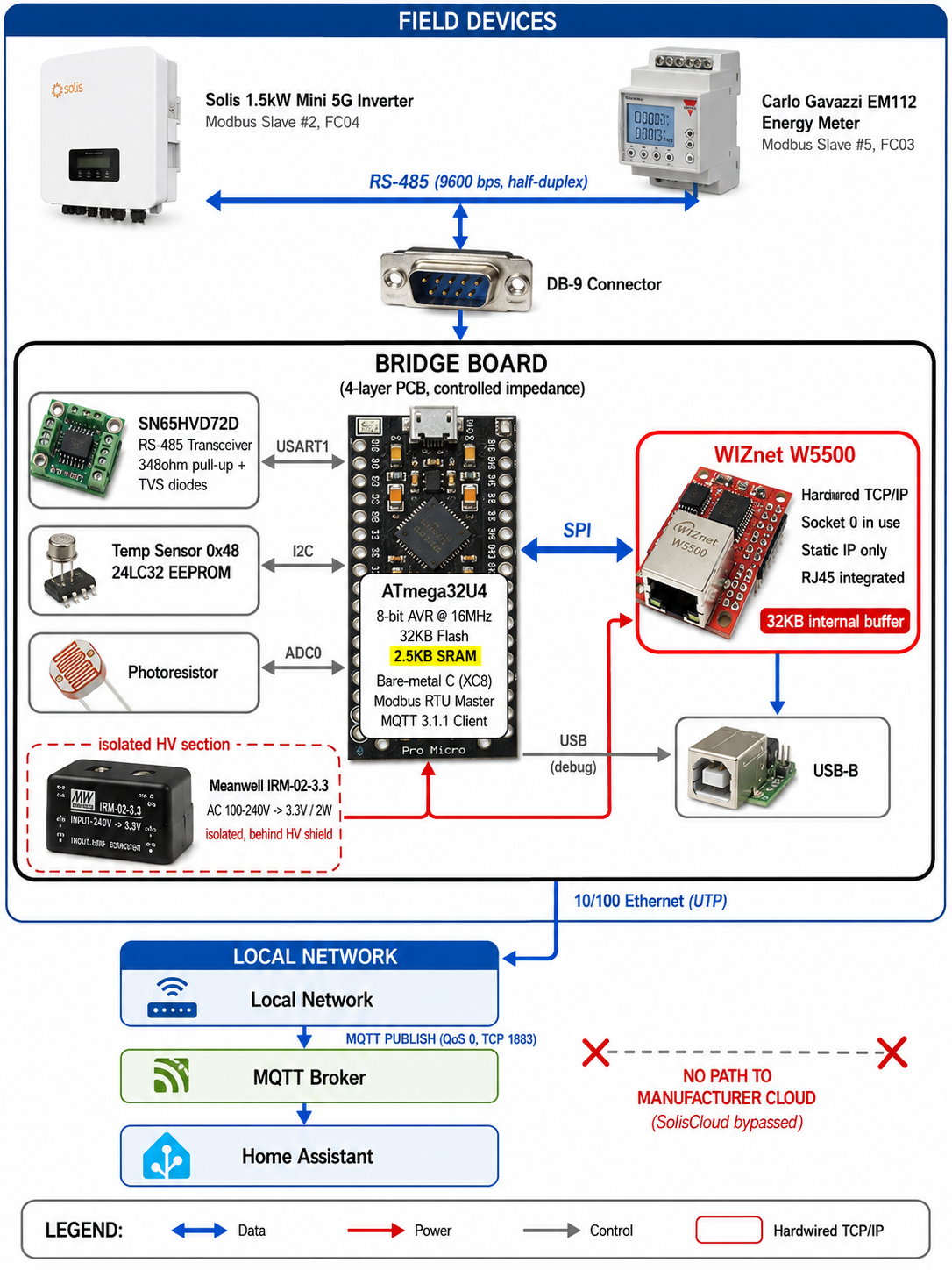
동작은 30초 주기로 반복됩니다. 먼저 인버터의 레지스터 하나를 프로브해 생존을 확인하고, 살아 있으면 9개 항목을, 응답이 없으면(야간 슬립 등) 전 항목을 0으로 발행합니다. 이어 온도와 조도를 읽어 총 12개 MQTT 토픽에 발행합니다.
인버터 레지스터 맵 (슬레이브 2번, FC04)
| 레지스터 | 항목 | 워드 | 비고 |
|---|---|---|---|
| 3004 | AC 발전 전력 | 2 | 워드 순서 리틀엔디안 |
| 3008 | 누적 발전량 | 2 | 워드 순서 리틀엔디안 |
| 3014 | 금일 발전량 | 1 | ÷10 |
| 3021 / 3022 | DC 전압 / 전류 | 1 | ÷10 |
| 3035 / 3038 | AC 전압 / 전류 | 1 | ÷10 |
| 3041 / 3042 | 기기 온도 / 계통 주파수 | 1 | 온도 signed, 주파수 ÷100 |
MQTT 토픽은 /home/solarpv/(online, gridpower, pvvolt, pvamp, gridvolt, gridcurrent, gridfrequency, devicetemp, totalpower, todaypower)와 /home/shed/(temperature, light)로 나뉩니다.
기술 배경
RS-485 — 왜 인버터는 아직도 이 규격을 쓰는가
RS-485는 두 가닥의 꼬임쌍선에 서로 반대 위상의 신호를 실어 보내는 차동 전송 규격입니다. 수신 측이 두 선의 전위 차이만 보기 때문에, 양쪽 선에 똑같이 실린 외부 노이즈는 상쇄되어 사라집니다. 이 성질 덕분에 모터와 인버터가 돌아가는 전기적으로 시끄러운 환경에서도 수백 미터를 견딥니다.
대신 대가가 있습니다. 한 쌍의 선을 여러 장치가 나눠 쓰는 반이중(half-duplex) 방식이라, 말할 차례를 정해줄 상위 프로토콜이 반드시 필요합니다. 또 유휴 상태에서 선의 전위가 뜨지 않도록 바이어싱 저항을 걸어야 하는데, 이 프로젝트는 348Ω 풀업과 보호 다이오드로 이를 처리했습니다. 앞서 언급한 1세대의 역설계 경험이 여기에 반영돼 있습니다.
Modbus RTU — 그리고 32비트 값의 함정
Modbus RTU는 RS-485 위에서 "말할 차례"를 정하는 프로토콜입니다. 마스터가 슬레이브 주소·함수 코드·레지스터 번지·개수를 담은 요청을 보내면, 해당 주소의 슬레이브만 응답합니다. 프레임 끝에는 CRC-16이 붙고, 프레임 사이에는 최소 3.5문자 시간의 침묵 구간을 둡니다. 이 프로젝트에서 MCU는 인버터(2번)와 에너지 미터(5번)를 순차 폴링하는 마스터 역할을 합니다.
실무에서 가장 자주 발목을 잡는 지점은 32비트 값의 워드 순서입니다. Modbus 레지스터는 16비트 단위여서 전력량 같은 큰 값은 두 레지스터에 나눠 담기는데, 어느 쪽이 상위 워드인지는 표준이 정해주지 않습니다. 이 프로젝트의 코드에도 항목마다 BYTEORDER_BIG / BYTEORDER_LITTLE을 지정하는 플래그가 남아 있습니다. 저자가 2세대 개발 당시 겪은 버그의 흔적입니다. 값이 터무니없이 크거나 음수로 나온다면 워드 순서를 가장 먼저 의심해야 합니다.
MQTT — 클라우드 종속을 끊는 지점
MQTT는 발행/구독 방식의 경량 메시징 프로토콜입니다. 장치는 목적지를 모른 채 토픽에 값을 발행하고, 브로커가 이를 구독자에게 전달합니다. 이 프로젝트가 쓰는 것은 MQTT 3.1.1의 CONNECT와 QoS-0 PUBLISH뿐입니다.
여기서 중요한 것은 기능이 아니라 위치입니다. 브로커가 인터넷 너머가 아니라 같은 LAN 안에 있기 때문에, 인버터 데이터는 집 밖으로 한 번도 나가지 않고 Home Assistant에 도착합니다. 앞서 살펴본 규제 논의가 겨냥하는 지점이 바로 이 경로의 소유권입니다.
기술 특징
베어메탈 C, 그리고 그 대가. 블로그 본문은 Arduino Leonardo 부트로더와 라이브러리를 활용했다고 적고 있지만, 공개된 저장소의 실체는 순수 베어메탈 C입니다. MPLAB XC8과 avr-libc 위에서 w5500.c, mqtt.c, modbus.c, spi.c, twi.c, uart.c를 전부 직접 구현했습니다. XC8이 AVR 전용 표준 라이브러리 확장을 노출하지 않아 부동소수점 문자열 변환 함수(dtostrf)까지 손으로 작성했을 정도입니다. 참고로 저자는 2세대 ESP32 코드를 ATmega32U4로 옮기는 과정에서 AI의 도움을 받았다고 밝히고 있습니다.
2.5KB가 코드를 자른 흔적. 자원 제약은 추상적인 이야기가 아니라 API 서명에 그대로 새겨져 있습니다.
- Modbus 응답 버퍼가 64바이트로 고정돼 있어, 한 번에 읽을 수 있는 레지스터가 최대 25개로 제한됩니다.
- MQTT 클라이언트에는 SUBSCRIBE도, QoS 1/2도, 재전송 큐도 없습니다. 발행만 가능합니다.
그런데 정작 TCP/IP만은 온전합니다. 재전송도, 흐름 제어도, 체크섬도 규격대로 동작합니다. 잘라낼 필요가 없었기 때문입니다. 그 부분은 MCU가 하는 일이 아닙니다.
3중 복구 구조. "2개월 무정지"는 운이 좋아서가 아닙니다.
- AVR 하드웨어 워치독(8초)이 상시 동작하며, 블로킹 가능성이 있는 모든 구간에서 리셋됩니다.
- 이더넷 링크나 브로커 연결이 끊기면 1초 간격으로 10회 재시도하고, 실패하면 리부트합니다.
- 네트워크 워치독 — 브로커로부터 확인된 활동이 90초(폴링 주기의 3배) 동안 없으면 강제 리부트합니다.
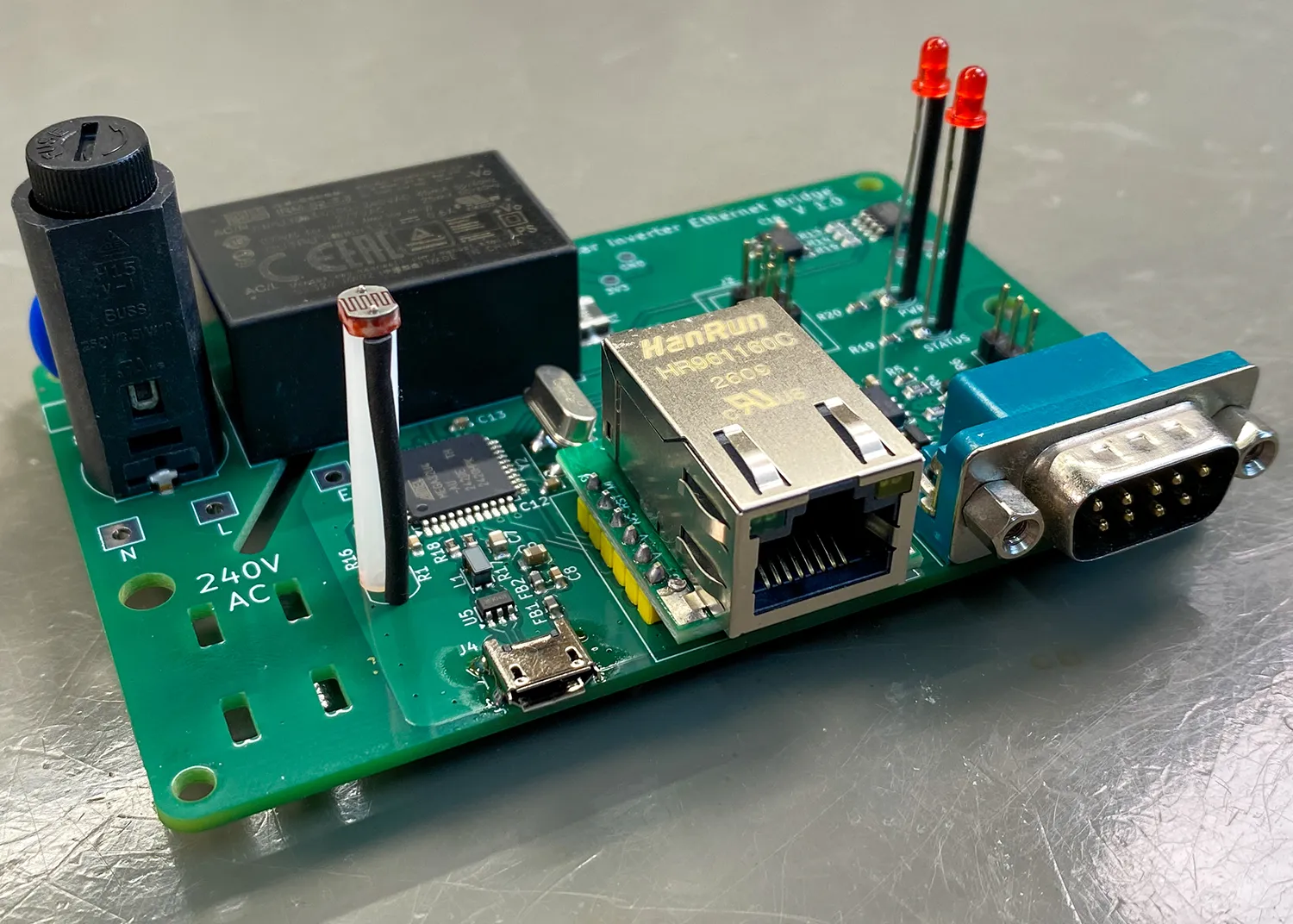
W5500이 들어가는 자리 — SRAM 2.5KB에 이더넷을 붙이는 법
이 프로젝트는 W5500을 RJ45 일체형 기성 SPI 모듈 형태로 채택했습니다. 저장소의 w5500.h 헤더를 보면 칩이 실제로 무엇을 하는지가 그대로 드러납니다.
MCU가 온도값 하나를 발행할 때 벌어지는 일을 순서대로 보겠습니다.
- MCU: Modbus 응답을 파싱해
"23.75"라는 문자열과/home/shed/temperature라는 토픽으로 MQTT PUBLISH 패킷을 조립합니다. - MCU: SPI 프레임
[주소 상위][주소 하위][컨트롤 바이트][데이터…]를 만들어 소켓 0의 TX 버퍼 블록에 이 바이트열을 씁니다. 컨트롤 바이트의 블록 선택 비트(BSB)가 "소켓 0의 송신 버퍼"를 가리킵니다. - MCU: 소켓 0의 명령 레지스터에
SEND(0x20) 한 바이트를 씁니다. MCU가 하는 일은 여기까지입니다. - W5500: 이 바이트열을 TCP 세그먼트로 나누고, 시퀀스 번호를 매기고, 체크섬을 계산하고, IP·이더넷 헤더를 붙이고, 목적지 MAC을 ARP로 확인하고, 회선에 내보냅니다.
- W5500: 상대의 ACK를 기다리다 오지 않으면 스스로 재전송합니다. 윈도 크기도 알아서 조절합니다.
- MCU: 나중에 상태 레지스터를 읽어 "보냈다" 혹은 "연결이 끊겼다" 는 결과만 확인합니다.
이 분업을 비유하자면 국제 배송 대행사에 가깝습니다. MCU는 물건과 받는 사람 주소만 창구에 건네고 돌아섭니다. 통관 서류, 운송장 번호, 분실 시 재발송은 대행사의 일입니다. MCU가 하지 않는 일은 핸드셰이크·시퀀스 관리·재전송·체크섬·ARP이고, MCU가 하는 일은 레지스터에 명령 한 바이트를 쓰는 것뿐입니다.
만약 이 칩이 없었다면 이 프로젝트는 성립하지 않았습니다. lwIP나 uIP 같은 소프트웨어 TCP/IP 스택은 재전송 큐, 소켓 버퍼, 상태 머신을 모두 RAM에 두어야 합니다. SRAM 2.5KB, Flash 32KB라는 예산에서는 스택 하나만으로도 여유가 사라집니다. 하물며 Modbus 마스터와 MQTT 클라이언트를 함께 올릴 자리는 없습니다. W5500은 소켓 버퍼 32KB를 MCU 바깥에 두어 이 예산 문제를 통째로 없앱니다.
구현상의 특징도 몇 가지 눈에 띕니다. 드라이버는 정적 IP 전용으로 작성돼 있고(DHCP 클라이언트 코드가 아예 없습니다), 8개 소켓 중 0번 하나만 MQTT 전용으로 예약해 씁니다. 나머지 7개는 유휴 상태입니다.
WIZnet Makers 유사 사례
How to Log Growatt Solar Inverter Data with W5500 on ESP32 — 태양광 인버터의 RS-485 Modbus 데이터를 W5500 유선 이더넷으로 내보내는, 기능과 용도가 가장 가까운 선행 사례입니다. 다만 목적지가 ThingSpeak 클라우드(120초 주기) 라는 점에서 본 프로젝트의 로컬 MQTT와 갈립니다.
→ 프로젝트 링크: https://maker.wiznet.io/jakelee/projects/how-to-log-growatt-solar-inverter-data-with-w5500-on-esp32/
Microcontroller for intelligent purchase and sale of electricity in the home — STM32F411이 Modbus RTU로 인버터와 통신하고 W5500이 이더넷을 담당하는 동일한 2계층 분업 구조입니다. PoE로 전원과 통신을 한 가닥에 통합했다는 점, 그리고 계측을 넘어 전력 매매를 자동 제어한다는 점이 다릅니다.
→ 프로젝트 링크: https://maker.wiznet.io/bruno/projects/microcontroller-for-intelligent-purchase-and-sale-of-electricity-in-the-home-according-to-current/
Plug-In-Battery (ESP32-C6 PV Bridge) — W5500 유선 이더넷 + MQTT + Home Assistant라는 소프트웨어 스택이 사실상 동일합니다. 대상이 인버터가 아닌 배터리 시스템이고, Home Assistant 노출을 Zigbee와 병행한다는 점이 차이입니다.
→ 프로젝트 링크: https://maker.wiznet.io/irina/projects/plug-in-battery-esp32-c6-pv-bridge/
세 사례 모두 "필드단의 RS-485와 Modbus는 MCU가, 네트워크단의 TCP/IP는 W5500이" 담당하는 같은 분업 구조를 택했습니다. 본 프로젝트는 그 검증된 패턴을 가장 극단적인 자원 조건에서 성립시킨 사례입니다.
| 항목 | 본 프로젝트 | Growatt Logger | 전력 매매 컨트롤러 | Plug-In-Battery |
|---|---|---|---|---|
| MCU | ATmega32U4 (8비트) | ESP32 | STM32F411 | ESP32-C6 |
| 자체 무선 보유 | 없음 | 있음 | 미상 | 있음 |
| 필드 프로토콜 | Modbus RTU | Modbus RTU | Modbus RTU | 미상 |
| 데이터 목적지 | 로컬 MQTT / HA | ThingSpeak 클라우드 | 클라우드 | 로컬 MQTT / HA |
| 급전 방식 | AC 직결 절연 PSU | 미상 | PoE | 미상 |
| WIZnet 칩 | W5500 | W5500 | W5500 | W5500 |
| TCP/IP 처리 | 칩 오프로딩 | 칩 오프로딩 | 칩 오프로딩 | 칩 오프로딩 |
MCU도, 급전 방식도, 데이터 목적지도 제각각이지만 네트워크 계층만은 네 프로젝트가 같은 선택을 했습니다. 본 프로젝트의 차별점은 무선을 아예 갖지 못한 8비트 MCU에서도 이 패턴이 동일하게 작동함을 보였다는 데 있습니다.
비즈니스 가치
외부 관점 — 고객과 시장
- 무선이 물리적으로 닿지 않는 설비의 계측 유선화. 지하 기계실, 옥외 캐비닛, 두꺼운 벽 너머의 부속 건물은 산업 현장에 흔합니다. 이런 곳에서는 프로토콜 최적화가 아니라 매체 자체를 바꾸는 것이 답입니다.
- 레거시 RS-485 자산의 IP 전환. 멀쩡히 동작하는 Modbus 장비를 교체하지 않고 네트워크에 편입시키는 브리지 패턴이며, BOM 기준 £37 수준으로 재현됩니다.
- 제조사 클라우드에 의존하지 않는 계측 경로. 앞서 본 리투아니아 법령과 EU NCCS의 방향을 고려하면, 이 수요는 유행이 아니라 규제가 떠받치는 구조적 수요입니다. 규제가 강화될수록 "원격 접근 경로를 끊고 로컬에서 읽는" 구성의 필요는 오히려 커집니다.
- 저전력 24/7 게이트웨이의 다수 배치. 게이트웨이 대수가 늘어날수록 SoC 대비 MCU 구성의 전력 격차가 누적됩니다.
내부 관점 — WIZnet
"MCU 자원이 부족할수록 W5500이 선택된다" 는 명제의 교과서적 사례입니다. 선택의 이유가 성능이나 가격이 아니라 애초에 다른 선택지가 없었다는 데 있기 때문입니다. SRAM 2.5KB는 소프트웨어 스택이 들어갈 수 없는 영역이며, 이 영역은 앞으로도 사라지지 않습니다.
생태계 각인 효과도 확인됩니다. Arduino의 공식 Ethernet Shield 2가 W5500 기반이라는 사실은, Arduino 계열에서 출발한 개발자에게 하드와이어드 이더넷이 사실상 기본값으로 자리 잡았음을 보여줍니다.
Arduino Ethernet Shield 2: https://docs.arduino.cc/retired/shields/arduino-ethernet-shield-2-with-poe/
가장 주목할 지점은 포지셔닝입니다. Arduino가 Opta와 Qualcomm 인수로 산업 시장에 들어가든, Raspberry Pi가 Compute Module로 같은 시장을 가져가든, 어느 플랫폼이 이기더라도 네트워크 계층은 결국 하드와이어드 TCP/IP로 수렴합니다. 산업 현장이 요구하는 것은 최신 코어가 아니라 끊기지 않는 링크와 예측 가능한 지연이기 때문입니다. 플랫폼 경쟁의 승패와 무관하게 수요가 발생하는 자리라는 점에서, WIZnet의 위치는 곡괭이와 삽에 가깝습니다.
한계 및 개선 방향
이 프로젝트는 제약 조건 안에서 목적을 정확히 달성했습니다. 다음 세대를 생각한다면 살펴볼 지점은 다음과 같습니다.
보안 계층이 없습니다. MQTT는 TCP 1883 평문으로 발행되고 자격증명도 소스에 하드코딩돼 있습니다. 로컬 LAN 안에서만 오가므로 실사용 위험은 제한적이지만, 앞서 인용한 규제 논의가 요구하는 방향과는 어긋납니다. 다만 TLS를 얹으려면 ATmega32U4로는 불가능합니다. 핸드셰이크 버퍼와 인증서 처리만으로 SRAM 예산을 초과하기 때문입니다. [추정]
확장 여지가 소켓에 남아 있습니다. W5500의 8개 소켓 중 1개만 쓰고 있으므로, 설정용 웹 UI나 두 번째 브로커, SNMP 에이전트를 추가 하드웨어 없이 붙일 수 있습니다. 이 경우에도 병목은 칩이 아니라 MCU의 SRAM입니다.
전원과 배선을 한 가닥으로 줄일 수 있습니다. 현재는 AC 직결 PSU와 별도의 UTP 케이블이 각각 필요합니다. 앞서 소개한 전력 매매 컨트롤러 사례처럼 PoE를 적용하면 옥외 설치 배선이 절반으로 줄어듭니다.
재현성 측면의 주의점이 있습니다. main.c에는 사용되지 않는 네트워크 설정 세트가 남아 있고, 실제 이더넷 설정(10.0.0.140/24)과 MQTT 브로커 주소(192.168.0.2)가 서로 다른 대역을 가리킵니다. 공개용으로 값을 정리하는 과정의 흔적으로 보이며, 그대로 빌드하면 브로커에 연결되지 않을 수 있습니다. [추정] README가 블로그 링크만 제시하는 점과 함께, 제3자가 재현하려면 이 부분을 먼저 손봐야 합니다.
상위 라인으로의 이행 경로. TLS와 다중 슬레이브, OTA 업데이트까지 원한다면 SRAM에 여유가 있는 MCU와 W55RP20이나 W6100 같은 상위 제품의 조합이 자연스러운 다음 단계입니다. 하드와이어드 소켓이라는 설계 원칙은 그대로 유지되므로, 이 프로젝트에서 검증한 구조는 그대로 이어집니다.
FAQ
Wi-Fi 대신 이더넷을 쓰면 실제로 얼마나 안정적인가요? 이 프로젝트 기준으로 2개월 연속 무정지이며, 그동안 전원 재투입이 필요 없었습니다. 비교 대상인 Wi-Fi 버전은 같은 위치에서 접속 실패와 프리즈를 반복했습니다. 다만 이 결과는 유선화 자체뿐 아니라 앞서 설명한 3중 복구 구조가 함께 만든 것으로 보아야 합니다.
8비트 MCU에도 이더넷을 붙일 수 있나요? 기준이 무엇인가요? 붙일 수 있습니다. 다만 소프트웨어 스택이 아니라 하드와이어드 TCP/IP 칩을 쓰는 경우에 한합니다. 이 프로젝트는 SRAM 2.5KB, Flash 32KB 환경에서 Modbus 마스터와 MQTT 클라이언트까지 함께 올렸습니다. 판단 기준은 코어의 비트 수가 아니라 SRAM 예산입니다.
Modbus 값이 이상하게 나올 때 무엇부터 의심해야 하나요? 32비트 값의 워드 순서입니다. 값이 비정상적으로 크거나 음수로 나온다면 상위·하위 워드를 바꿔 보십시오. 그다음으로는 스케일 팩터(÷10, ÷100)와 부호 있는 정수 처리를 확인하면 됩니다.
Solis 외의 인버터에도 적용할 수 있나요? 구조는 그대로 재사용할 수 있습니다. 필요한 것은 해당 인버터의 Modbus 레지스터 맵과 슬레이브 주소, 통신 속도뿐입니다. 제조사가 문서를 공개하지 않는 경우가 많아, 실제로는 이 자료 확보가 가장 큰 장벽입니다.
PoE를 적용하려면 무엇이 달라지나요? 이더넷 측에 PoE PD 컨트롤러와 절연형 DC-DC 단이 추가되고, AC 직결 PSU와 그에 따른 고전압 격리 설계를 덜어낼 수 있습니다. 기판 면적과 BOM은 늘지만 옥외 배선이 한 가닥으로 줄어들어 설치 난이도가 크게 내려갑니다.
No Wi-Fi in the Shed, Two Months Without a Reset — A Solis Inverter Modbus-to-MQTT Bridge Built on ATmega32U4 and W5500
Summary
UK maker Brian Dorey replaced a solar inverter logger that kept dropping off Wi-Fi with an ATmega32U4 + W5500 wired Ethernet bridge. The device reads Modbus RTU data from the inverter, publishes it to a local MQTT broker, and feeds Home Assistant without touching the manufacturer's cloud. The remarkable part is the MCU: an 8-bit AVR with 2.5KB of SRAM. Ethernet works here only because the TCP/IP stack lives inside the chip, not in firmware.
Overview
Most residential solar inverters ship data to the cloud through a manufacturer-supplied Wi-Fi dongle. That convenience carries two costs. Your data leaves your hands, and when the wireless link drops, so does your monitoring.
This particular inverter sits in a shed away from the house, with more than two meters of stone and concrete between it and the router. The author's earlier ESP32 Wi-Fi bridge failed and froze repeatedly against that wall. No antenna swap or smarter reconnect logic was going to fix it.
So he went wired — with one constraint attached. The design could not slide back to the power draw of the Raspberry Pi era, which ran at 2 to 5 watts. This article covers how he satisfied both conditions by pairing an 8-bit MCU with a hardwired TCP/IP chip.
Original post: https://www.briandorey.com/post/solis-inverter-rs485-ethernet-bridge
Solving the Same Problem Three Times
This bridge did not appear out of nowhere. The author spent four years attacking the same problem three separate times.
| Gen 1 (2022-05) | Gen 2 (2022-10) | Gen 3 (2026-08) | |
|---|---|---|---|
| Compute platform | Raspberry Pi 3 | ESP32-WROOM-32U | ATmega32U4 (8-bit AVR) |
| RS-485 | RS485 Pi board | SN65HVD72D | SN65HVD72D |
| Network | Pi onboard | Wi-Fi (external antenna) | W5500 wired Ethernet |
| Software | Python 3 + minimalmodbus + paho.mqtt | ESP32 firmware (C) | Bare-metal C (XC8) |
| Power draw | 2–5W | 0.2–0.5W | Not measured |
| Why it was retired | Excessive power draw | Link failures behind stone walls | Current design (two months, no reset) |
The compute platform got lighter with every generation. It started on a SoC running Linux and ended on an 8-bit microcontroller with 2.5KB of SRAM. Yet exactly one layer moved in the opposite direction: TCP/IP. What the Linux kernel handled in Gen 1, and the ESP-IDF software stack handled in Gen 2, moved into dedicated silicon in Gen 3.
The reasons for retirement differ, and that is worth noting. Gen 1 failed on power; Gen 2 failed on physics. Neither problem yields to software optimization, which is why the hardware architecture changed each time.
As an aside, the RS-485 biasing scheme in Gen 3 is inherited from Gen 1. Back then the author could not talk to the inverter at all, so he put the manufacturer's Wi-Fi logger under a microscope and reverse-engineered the pull-up and pull-down resistors on the A and B lines.
Gen 1 post: https://www.briandorey.com/post/solar-upgrade-solis-1-5kw-inverter-raspberry-pi-rs485-logging
Why Pulling the Inverter Local Matters
Repository adoption: not confirmed. The GitHub repository shows zero stars, forks, and watchers. It is an individual DIY project published under the MIT license. No press coverage or reporting indicates adoption by any company or institution.
Repository: https://github.com/briandorey/solis-inverter-ethernet-bridge
Industrial and regulatory need: confirmed. The problem statement itself — separating an inverter from its vendor cloud — is already on the European regulatory agenda.
- Lithuania's Electricity Law amendment — passed by parliament in 2024 with 79 votes in favor. New plants above 100kW must comply from May 1, 2025, and existing installations from May 1, 2026, adding security measures to their inverters and information management systems. The law explicitly treats remote access to inverters as a risk.
- Reuters report, May 2025 — undocumented communication modules found in Chinese-made inverters triggered alarm across Europe.
- Two European Parliament written questions (2025) — a toolbox to restrict high-risk PV inverters (P-001967/2025) and the risks of hidden communication modules (E-002219/2025).
- EU Network Code on Cybersecurity (NCCS, Regulation (EU) 2024/1366) — entered into force in March 2024.
Lithuanian legislation: https://www.pv-tech.org/lithuania-to-block-chinese-inverters-with-cybersecurity-legislation/ Reuters coverage: https://www.pv-magazine.com/2025/05/14/hidden-devices-found-in-chinese-made-inverters-in-the-us-reports-reuters/ EU NCCS: https://energy.ec.europa.eu/news/new-network-code-cybersecurity-eu-electricity-sector-2024-03-11_en
The two conclusions diverge, and we present them as they are. At the repository level this is a hobby project, but its problem statement points the same direction as the regulation.
An Industry Trend Worth Noting
Open-source hardware vendors are moving into industrial markets, and that context matters. Arduino launched Opta, its first industrial micro PLC, in November 2022. The Opta RS485 variant packages exactly what this project built by hand: Ethernet plus RS-485. In 2025, Qualcomm acquired Arduino, making the direction unmistakable. Raspberry Pi followed a parallel path, publishing a microcontroller deck aimed at industrial customers in March 2025 and shipping Compute Module 5.
Arduino Opta: https://blog.arduino.cc/2022/11/08/welcome-opta-our-first-ever-micro-plc-with-industrial-iot-capabilities/ Qualcomm acquires Arduino: https://www.embedded.com/qualcomm-acquires-arduino-keeping-the-open-source-spirit-alive/ Raspberry Pi industrial materials: https://www.raspberrypi.com/app/uploads/2025/03/Industrial-Customer-Presentation_Microcontrollers.pdf
That said, Opta (2022) predates this project's third generation (2026), so we cannot claim the community moved before the vendors did. The more interesting observation runs the other way. People keep building their own even though a commercial product already exists, which suggests power, form factor, and cost requirements that off-the-shelf hardware still fails to meet. [Inferred]
Architecture
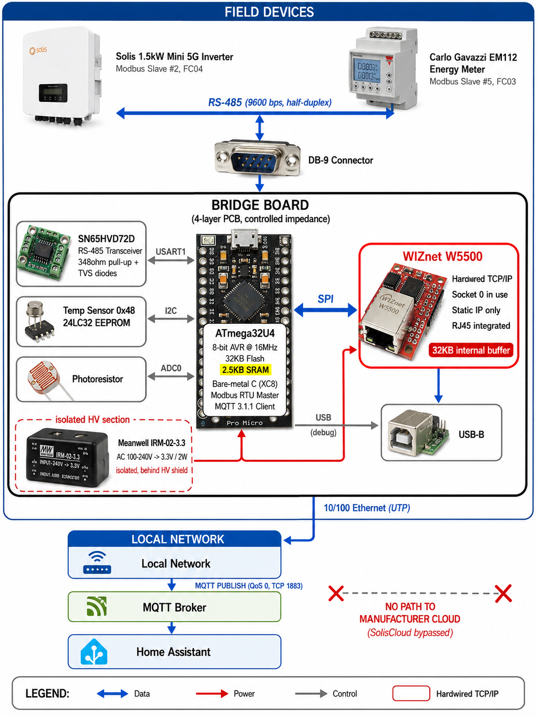
The cycle repeats every 30 seconds. The firmware first probes a single inverter register to confirm the device is alive. If it responds, nine values are read; if it does not — at night, for instance — every value is published as 0. Temperature and light readings follow, filling 12 MQTT topics in total.
Inverter Register Map (Slave 2, FC04)
| Register | Value | Words | Notes |
|---|---|---|---|
| 3004 | AC output power | 2 | Little-endian word order |
| 3008 | Lifetime energy | 2 | Little-endian word order |
| 3014 | Energy today | 1 | ÷10 |
| 3021 / 3022 | DC voltage / current | 1 | ÷10 |
| 3035 / 3038 | AC voltage / current | 1 | ÷10 |
| 3041 / 3042 | Device temperature / grid frequency | 1 | Temperature signed, frequency ÷100 |
MQTT topics split into /home/solarpv/ (online, gridpower, pvvolt, pvamp, gridvolt, gridcurrent, gridfrequency, devicetemp, totalpower, todaypower) and /home/shed/ (temperature, light).
Technology Background
RS-485 — Why Inverters Still Use It
RS-485 is a differential standard that sends opposite-phase signals down a twisted pair. The receiver reads only the difference between the two lines, so noise induced equally on both cancels out. That property lets the link survive hundreds of meters in electrically noisy spaces full of motors and inverters.
There is a cost. Multiple devices share one pair in half-duplex, so a higher-level protocol must decide who talks and when. The lines also need biasing resistors to hold a defined idle state, which this project handles with 348-ohm pull-ups and protection diodes. The Gen 1 reverse-engineering work shows up right here.
Modbus RTU — And the 32-Bit Trap
Modbus RTU is the protocol that arbitrates the RS-485 bus. The master sends a request carrying a slave address, function code, register number, and count, and only the addressed slave answers. Each frame ends with a CRC-16, and frames are separated by at least 3.5 character times of silence. Here the MCU acts as the master polling the inverter (address 2) and the energy meter (address 5) in sequence.
The most common field problem is word order in 32-bit values. Modbus registers are 16 bits wide, so large values such as cumulative energy span two registers — and the standard never says which register holds the high word. This project's code still carries per-value BYTEORDER_BIG and BYTEORDER_LITTLE flags, a residue of bugs the author hit during Gen 2 development. When a reading comes back absurdly large or unexpectedly negative, suspect word order first.
MQTT — Where Cloud Dependency Ends
MQTT is a lightweight publish/subscribe messaging protocol. A device publishes values to a topic without knowing the destination, and the broker forwards them to subscribers. This project implements only CONNECT and QoS-0 PUBLISH from MQTT 3.1.1.
What matters here is not the feature set but the location. Because the broker sits on the same LAN rather than across the internet, inverter data reaches Home Assistant without ever leaving the property. Ownership of that path is exactly what the regulations discussed above are aiming at.
Technical Highlights
Bare-metal C, and what it costs. The blog post describes using the Arduino Leonardo bootloader and libraries, but the published repository tells a different story: pure bare-metal C. On top of MPLAB XC8 and avr-libc, the author wrote w5500.c, mqtt.c, modbus.c, spi.c, twi.c, and uart.c himself. XC8 does not expose the AVR-specific standard library extensions, so he even hand-wrote the float-to-string function (dtostrf). He also notes that AI assisted the port of the Gen 2 ESP32 code to the ATmega32U4.
Where 2.5KB cut into the code. Resource limits are not abstract here — they are visible in the API signatures.
- The Modbus response buffer is fixed at 64 bytes, capping a single read at 25 registers.
- The MQTT client has no SUBSCRIBE, no QoS 1 or 2, and no retransmit queue. It publishes, and nothing else.
Yet TCP/IP arrives intact. Retransmission, flow control, and checksums all behave exactly as specified, because nothing had to be trimmed. That part is not the MCU's job.
Three layers of recovery. Two months without a reset is not luck.
- The AVR hardware watchdog (8 seconds) runs continuously and is kicked at every point where the code might block.
- When the Ethernet link or the broker connection drops, the firmware retries ten times at one-second intervals and reboots on failure.
- A network watchdog forces a reboot when the broker shows no confirmed activity for 90 seconds — three polling cycles.
Where WIZnet Fits — Putting Ethernet on 2.5KB of SRAM
The project uses a W5500 in the form of an off-the-shelf SPI module with an integrated RJ45 jack. The repository's w5500.h header spells out exactly what the chip does.
Here is what happens when the MCU publishes a single temperature reading.
- MCU: parses the Modbus response and assembles an MQTT PUBLISH packet carrying the string
"23.75"and the topic/home/shed/temperature. - MCU: builds an SPI frame of
[address high][address low][control byte][data…]and writes those bytes into socket 0's TX buffer block. The block-select bits in the control byte point at "socket 0, transmit buffer." - MCU: writes a single byte,
SEND(0x20), to socket 0's command register. The MCU's work ends here. - W5500: segments the byte stream into TCP packets, assigns sequence numbers, computes checksums, attaches IP and Ethernet headers, resolves the destination MAC through ARP, and puts the frames on the wire.
- W5500: waits for the peer's ACK and retransmits on its own if none arrives. It manages the window size too.
- MCU: later reads a status register to learn one of two things — the data went out, or the connection dropped.
Think of it as an international shipping agent. The MCU hands over a package and an address at the counter, then walks away. Customs paperwork, tracking numbers, and reshipping lost parcels belong to the agent. What the MCU does not do is handshaking, sequence management, retransmission, checksums, and ARP. What it does is write one command byte to a register.
Without this chip, the project would not exist. Software TCP/IP stacks such as lwIP or uIP must keep retransmit queues, socket buffers, and state machines in RAM. On a budget of 2.5KB SRAM and 32KB Flash, the stack alone consumes the margin — leaving no room for a Modbus master and an MQTT client alongside it. The W5500 removes the problem entirely by holding its 32KB of socket buffers outside the MCU.
A few implementation details stand out. The driver is written for static IP only — there is no DHCP client code at all — and it reserves just one of the eight sockets, socket 0, for MQTT. The remaining seven sit idle.
Similar Projects on WIZnet Makers
How to Log Growatt Solar Inverter Data with W5500 on ESP32 — the closest match in both function and purpose, moving RS-485 Modbus data from a solar inverter out over W5500 wired Ethernet. It diverges on destination, sending readings to ThingSpeak in the cloud every 120 seconds rather than a local MQTT broker.
→ Project link: https://maker.wiznet.io/jakelee/projects/how-to-log-growatt-solar-inverter-data-with-w5500-on-esp32/
Microcontroller for intelligent purchase and sale of electricity in the home — the same two-layer split, with an STM32F411 speaking Modbus RTU to the inverter and a W5500 handling Ethernet. It differs by combining power and data on one cable through PoE, and by controlling electricity trading rather than only measuring.
→ Project link: https://maker.wiznet.io/bruno/projects/microcontroller-for-intelligent-purchase-and-sale-of-electricity-in-the-home-according-to-current/
Plug-In-Battery (ESP32-C6 PV Bridge) — effectively the same software stack: W5500 wired Ethernet plus MQTT plus Home Assistant. It targets a battery system instead of an inverter and exposes values to Home Assistant over Zigbee in parallel.
→ Project link: https://maker.wiznet.io/irina/projects/plug-in-battery-esp32-c6-pv-bridge/
All three adopt the same division of labor: the MCU owns RS-485 and Modbus at the field layer, and the W5500 owns TCP/IP at the network layer. This project proves that pattern holds under the most extreme resource constraints of the group.
| Item | This project | Growatt Logger | Electricity trading controller | Plug-In-Battery |
|---|---|---|---|---|
| MCU | ATmega32U4 (8-bit) | ESP32 | STM32F411 | ESP32-C6 |
| Onboard wireless | None | Yes | Unknown | Yes |
| Field protocol | Modbus RTU | Modbus RTU | Modbus RTU | Unknown |
| Data destination | Local MQTT / HA | ThingSpeak cloud | Cloud | Local MQTT / HA |
| Power delivery | Isolated AC-DC onboard | Unknown | PoE | Unknown |
| WIZnet chip | W5500 | W5500 | W5500 | W5500 |
| TCP/IP handling | Chip offload | Chip offload | Chip offload | Chip offload |
The MCUs differ, the power schemes differ, and the destinations differ — yet all four projects made the same choice at the network layer. What sets this one apart is showing the pattern still works on an 8-bit MCU with no wireless capability at all.
Business Value
External View — Customers and Markets
- Wiring up equipment wireless cannot reach. Basements, plant rooms, outdoor cabinets, and outbuildings behind thick walls are everywhere in industry. In those places the answer is changing the medium, not tuning the protocol.
- Bringing legacy RS-485 assets onto IP. The bridge pattern connects working Modbus equipment to the network without replacing it, reproducible at a BOM cost around £37.
- A measurement path that does not depend on a vendor cloud. Given the Lithuanian legislation and the EU NCCS, this is not a passing trend but structural demand underwritten by regulation. As the rules tighten, the need to cut remote access and read locally only grows.
- Low-power gateways deployed at scale. The power gap between an MCU design and an SoC compounds with every additional gateway.
Internal View — WIZnet
This is a textbook case of the proposition that the tighter the MCU's resources, the more certain the W5500 becomes. The reason is not performance or price: there was no alternative. A 2.5KB SRAM budget is territory a software stack simply cannot enter, and that territory is not going away.
The ecosystem effect is visible too. Arduino's official Ethernet Shield 2 is built on the W5500, which tells you that hardwired Ethernet has become the default for developers who start in the Arduino world.
Arduino Ethernet Shield 2: https://docs.arduino.cc/retired/shields/arduino-ethernet-shield-2-with-poe/
The positioning point deserves the most attention. Whether Arduino takes the industrial market with Opta under Qualcomm, or Raspberry Pi takes it with Compute Module, the network layer converges on hardwired TCP/IP either way. What industrial sites demand is not the newest core but a link that stays up and latency you can predict. Demand arises regardless of who wins the platform race, which puts WIZnet closer to picks and shovels than to any single horse.
Limitations and Future Improvements
The project achieves exactly what it set out to do within its constraints. For a next generation, these are the points worth examining.
There is no security layer. MQTT publishes over plaintext TCP 1883, and credentials are hardcoded in the source. Real-world exposure is limited because traffic stays on the local LAN, but this runs against the direction of the regulations cited earlier. Adding TLS is not possible on an ATmega32U4 — handshake buffers and certificate handling alone exceed the SRAM budget. [Inferred]
Room to grow sits in the sockets. Only one of the W5500's eight sockets is in use, so a configuration web UI, a second broker, or an SNMP agent could be added without any additional hardware. Even then, the bottleneck would be the MCU's SRAM, not the chip.
Power and cabling could collapse into one run. Today the design needs an AC-connected PSU and a separate UTP cable. Adding PoE, as the electricity trading controller above does, would halve the outdoor wiring.
One caution about reproducibility. main.c still contains an unused network configuration block, and the active Ethernet settings (10.0.0.140/24) point to a different subnet than the MQTT broker address (192.168.0.2). This looks like leftover cleanup for publication, and building the code as-is may fail to reach the broker. [Inferred] Combined with a README that only links to the blog, anyone reproducing the build should fix this first.
A path to higher-end parts. If TLS, multiple slaves, and OTA updates are on the list, the natural next step pairs an MCU with more SRAM against a part such as the W55RP20 or W6100. The hardwired socket principle stays the same, so everything this project validated carries forward.
FAQ
How much more reliable is Ethernet than Wi-Fi in practice?
In this project, two months of continuous operation with no power cycling. The Wi-Fi version it replaced failed and froze repeatedly in the same location. Credit belongs partly to the wired link and partly to the three-layer recovery design described above.
Can an 8-bit MCU really run Ethernet? What is the threshold?
Yes — but only with a hardwired TCP/IP chip rather than a software stack. This design fits a Modbus master and an MQTT client alongside Ethernet in 2.5KB of SRAM and 32KB of Flash. The deciding factor is not the core's bit width but the SRAM budget.
A Modbus reading looks wrong. What should I check first? Word order in 32-bit values.
If a number comes back absurdly large or negative, swap the high and low words. After that, verify the scaling factor (÷10, ÷100) and signed-integer handling.
Will this work with inverters other than Solis?
The structure transfers directly. All you need is the target inverter's Modbus register map, slave address, and baud rate. Many manufacturers do not publish these, so obtaining that documentation is usually the real obstacle.
What changes if I want PoE?
You add a PoE PD controller and an isolated DC-DC stage on the Ethernet side, and you drop the AC-connected PSU along with its high-voltage isolation requirements. Board area and BOM cost rise, but outdoor wiring collapses to a single cable, which sharply lowers installation effort.