
Ethernet PHY and Its Interfaces: From MII to XGMII
Ethernet is a cornerstone of data communication, and at its core is the PHY (Physical Layer).
Ethernet is a cornerstone of data communication, and at its core is the PHY (Physical Layer). The PHY serves as an interface between the physical communication medium and the digital device. In this article, we aim to explain Ethernet PHY and its interfaces.
Basics of Ethernet PHY
Ethernet PHY, short for Physical Layer, is an integral component in Ethernet communication. It's responsible for the actual transmission and reception of data packets over the network. The PHY layer ensures that data is transmitted with integrity and reliability, converting the digital data from the MAC (Media Access Control) layer into electrical signals suitable for transmission over the network medium, be it copper wire, optical fiber, or others.
Types of Ethernet PHY Interfaces
Over the years, as Ethernet technology evolved, so did the interfaces connecting the MAC and PHY layers. These interfaces have adapted to cater to varying data rates and application requirements:
MII (Media Independent Interface) - A Detailed Overview
Definition and Purpose:
The Media Independent Interface (MII) is a standard interface used to connect a Fast Ethernet (i.e., 100 Mbps) media access control (MAC) block to a PHY chip. In essence, MII acts as the communication bridge between the MAC and the PHY, allowing data to be transmitted and received between them.
Historical Context:
Introduced in the mid-1990s, MII was developed as part of the IEEE 802.3u standard for Fast Ethernet. It was designed to be media-independent, meaning it could support a variety of physical media types, such as twisted pair cables or optical fibers.
Signal Details:
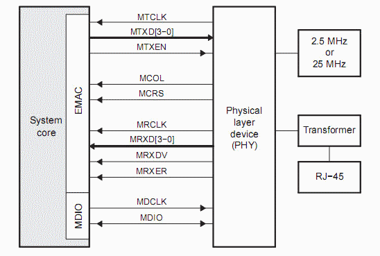
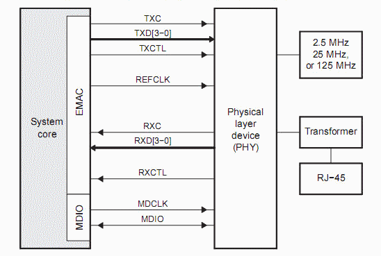
MII consists of a collection of signals, each with a specific function:
- TXD[0..3]: These are the transmit data lines. Data from the MAC to the PHY is sent over these lines in 4-bit nibbles.
- RXD[0..3]: These are the receive data lines. The PHY sends data to the MAC over these lines, also in 4-bit nibbles.
- REF_CLK: This is the reference clock. It provides a timing reference for data transmission and reception.
- TX_EN: Transmit Enable signal. It indicates when valid transmit data is present on the TXD lines.
- RX_ERR: Receive Error signal. It indicates when there's an error in the data received by the MAC.
- CRS: Carrier Sense. It indicates that the PHY detects a signal on the network medium.
- MDIO and MDC: Management Data Input/Output and Management Data Clock. These are used for management and configuration of the PHY.
Data Transmission:
The data bus width for MII is 4 bits, which means data is transmitted in 4-bit chunks or nibbles. With a clock rate of 25 MHz, this allows for the transmission of 100 Mbps, aligning with the Fast Ethernet standard.
Evolution and Variants:
While MII was groundbreaking during its introduction, the need for higher data rates and more efficient interfaces led to the development of several variants, including RMII (Reduced MII), GMII (Gigabit MII), and others. Each of these was designed to cater to specific requirements and challenges posed by evolving network technologies.
MII has played a foundational role in shaping Ethernet communication, especially in the realm of Fast Ethernet. Its design principles and the flexibility it offered paved the way for subsequent innovations in Ethernet technology. Understanding MII is essential for anyone delving deep into the intricacies of network design and communication.
RMII (Reduced Media Independent Interface) - An In-depth Look
Definition and Purpose:
The Reduced Media Independent Interface (RMII) is a modified version of the standard Media Independent Interface (MII). It was developed to address the need for a more streamlined interface that uses fewer pins while still maintaining the ability to support Fast Ethernet (100 Mbps) communication. RMII achieves this by reducing the number of data and control signals, making it a more cost-effective and space-efficient solution, especially for devices with limited pin availability.
Key Differences from MII:
While MII uses a 4-bit wide data bus for both transmission and reception, RMII reduces this to a 2-bit wide data bus. This reduction is achieved without compromising the data rate by doubling the clock frequency.
Signal Details:
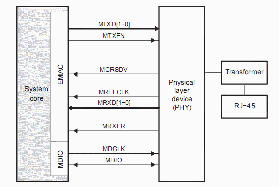
RMII retains some of the signals from MII but introduces changes to reduce the overall pin count:
- TXD[0..1]: These are the transmit data lines. Data from the MAC to the PHY is sent over these lines in 2-bit chunks.
- RXD[0..1]: These are the receive data lines. The PHY sends data to the MAC over these lines, also in 2-bit chunks.
- REF_CLK: In RMII, this clock runs at 50 MHz, which is double the frequency of MII's 25 MHz. This higher clock rate compensates for the reduced data bus width, ensuring the 100 Mbps data rate is maintained.
- TX_EN: Transmit Enable signal. It indicates when valid transmit data is present on the TXD lines.
- CRS_DV (Carrier Sense/Data Valid): This is a combined signal in RMII. It serves the dual purpose of indicating the presence of a signal on the network medium (Carrier Sense) and that the received data is valid (Data Valid).
- MDIO and MDC: Just like in MII, these signals are used for the management and configuration of the PHY.
Benefits of RMII:
1. Reduced Pin Count: By minimizing the number of data and control signals, RMII offers a more compact interface, which is especially beneficial for devices with limited available pins.
2. Cost Efficiency: Fewer pins mean smaller and cheaper connectors, leading to cost savings in device manufacturing.
3. Compatibility: RMII is designed to be compatible with existing MII PHYs, allowing for a smoother transition and integration into existing systems.
RMII is a testament to the continuous evolution of Ethernet technology. By addressing the challenges posed by device miniaturization and the need for cost-effective solutions, RMII has carved its niche in the realm of Fast Ethernet communication. It serves as a reminder of the importance of adaptability and innovation in the ever-evolving world of networking.
GMII (Gigabit Media Independent Interface) - A Comprehensive Examination
Definition and Purpose:
The Gigabit Media Independent Interface (GMII) is an interface standard used for connecting Gigabit Ethernet (1 Gbps) MAC blocks to PHY chips. As the successor to MII and RMII, GMII was developed to cater to the increased data rates of Gigabit Ethernet, ensuring efficient and reliable data transmission at ten times the speed of its predecessors.
Historical Context:
With the rapid growth of internet usage and data-intensive applications in the late 1990s and early 2000s, there was a pressing need for faster network speeds. GMII was introduced as part of the IEEE 802.3ab standard in 1999 to address this demand, providing a robust interface for 1 Gbps Ethernet communication.
Signal Details:
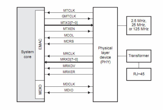
GMII expands on the signals of MII to accommodate the higher data rates:
- TXD[0..7]: These are the transmit data lines. Unlike MII's 4-bit and RMII's 2-bit data buses, GMII uses an 8-bit wide data bus for transmission, allowing for faster data transfer.
- RXD[0..7]: These are the receive data lines, also 8-bit wide, facilitating the reception of data from the PHY to the MAC.
- GTX_CLK and RX_CLK: These are the transmit and receive clocks, respectively. In GMII, the clock frequency is 125 MHz, five times that of MII.
- TX_EN: Transmit Enable signal, indicating when valid transmit data is present on the TXD lines.
- RX_DV (Receive Data Valid): This signal indicates that the data being received on the RXD lines is valid.
- RX_ER (Receive Error): It indicates an error in the received data.
- MDIO and MDC: Retained from MII and RMII, these signals are used for the management and configuration of the PHY.
Data Transmission:
With its 8-bit data bus and a clock rate of 125 MHz, GMII can achieve data rates of 1 Gbps, aligning with the Gigabit Ethernet standard.
Evolution and Subsequent Interfaces:
The continuous demand for even faster network speeds led to the development of subsequent interfaces like RGMII (Reduced Gigabit MII), SGMII (Serial GMII), and XGMII (10-Gigabit MII), each designed to cater to specific challenges and requirements of evolving network technologies.
GMII marked a significant leap in Ethernet technology, bridging the gap between Fast Ethernet and the era of Gigabit communication. Its introduction played a pivotal role in meeting the data demands of the new millennium, setting the stage for the high-speed networks we rely on today. Understanding GMII provides valuable insights into the progression of Ethernet interfaces and the continuous drive for faster and more efficient communication.
RGMII (Reduced Gigabit Media Independent Interface) - An In-depth Exploration
Definition and Purpose:
The Reduced Gigabit Media Independent Interface (RGMII) is an interface standard designed as a modification of the GMII. Its primary purpose is to reduce the number of pins required for Gigabit Ethernet connections, making it more suitable for applications with limited pin availability, such as in smaller devices or integrated systems.
Key Differences from GMII:
RGMII maintains the data rate of GMII (1 Gbps) but reduces the pin count by half. This is achieved by doubling the data rate on the fewer pins and utilizing both the rising and falling edges of the clock.
Signal Details:
RGMII simplifies the GMII signal set while ensuring the same data rate:
- TXD[0..3] and RXD[0..3]: These are the transmit and receive data lines, respectively. Unlike GMII's 8-bit data buses, RGMII uses 4-bit wide data buses for both transmission and reception. The data rate is maintained by transmitting data on both rising and falling edges of the clock.
- RGMII_TX_CTL and RGMII_RX_CTL: These are the transmit and receive control signals, respectively. They replace the TX_EN and RX_DV signals of GMII.
- RGMII_TX_CLK and RGMII_RX_CLK: These are the transmit and receive clocks, respectively. Both operate at 125 MHz, similar to GMII. However, in RGMII, data is clocked on both the rising and falling edges, effectively doubling the data rate on the 4-bit wide buses.
- MDIO and MDC: These signals, used for PHY management and configuration, remain consistent with both MII and GMII.
Benefits of RGMII:
1. Reduced Pin Count: RGMII significantly reduces the number of required pins compared to GMII, making it more suitable for devices with space constraints.
2. Cost Efficiency: With fewer pins, the connectors and interface hardware can be smaller and more cost-effective, leading to savings in device manufacturing.
3. Compatibility: RGMII is designed to be compatible with GMII, allowing for seamless integration into existing systems without the need for significant redesign.
RGMII represents a thoughtful evolution in Ethernet interface design, addressing the challenges of device miniaturization while ensuring high-speed data transmission. Its introduction has enabled the proliferation of Gigabit Ethernet in a wider range of devices and applications, showcasing the adaptability and forward-thinking nature of Ethernet technology.
SGMII (Serial Gigabit Media Independent Interface) - A Thorough Examination
Definition and Purpose:
The Serial Gigabit Media Independent Interface (SGMII) is a variant of the standard GMII interface. It's designed to transport Gigabit Ethernet over fewer pins by serializing the data, making it particularly advantageous for applications where board space and pin count are at a premium.
Key Characteristics:
Unlike GMII or RGMII, which are parallel interfaces, SGMII is a serial interface. This means it transmits data one bit at a time, but at a much higher clock rate, allowing it to achieve Gigabit speeds.
Signal Details:
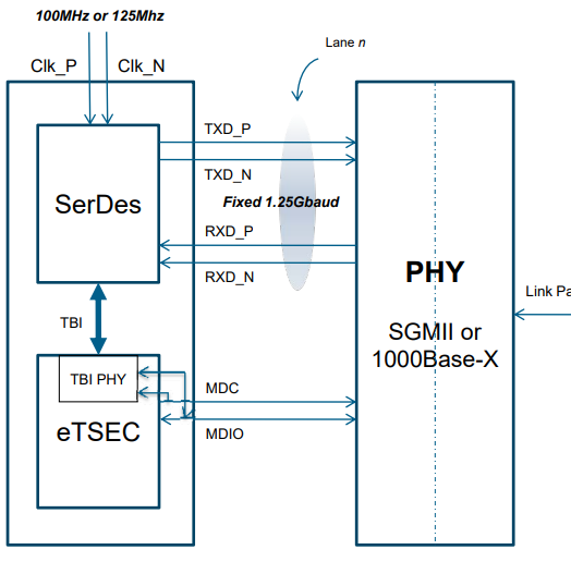
SGMII simplifies the interface by serializing the data:
- TX and RX: These are the primary transmit and receive data lines. In SGMII, data is serialized, meaning these lines carry one bit at a time but at a much faster rate compared to parallel interfaces.
- TX_CLK and RX_CLK: These are the transmit and receive clocks. Unlike the fixed 125 MHz clocks in GMII and RGMII, the clock rate in SGMII can vary. Typically, it operates at a frequency that matches the data rate, such as 625 MHz for 1 Gbps operation.
- MDIO and MDC: These management and configuration signals are consistent with MII, GMII, and RGMII.
Operational Modes:
SGMII can operate in different modes:
1. Copper Mode: In this mode, SGMII interfaces directly with a copper-based physical layer, such as twisted-pair cables.
2. Fiber Mode: SGMII can also interface with a fiber-based physical layer, allowing for longer-distance communication over optical fibers.
3. Auto-Negotiation Mode: SGMII supports auto-negotiation, where the interface can automatically determine the best speed and mode of operation based on the capabilities of the connected devices.
Benefits of SGMII:
1. Space Efficiency: By serializing the data and reducing the pin count, SGMII is ideal for compact devices where space is a constraint.
2. Flexibility: SGMII's ability to interface with both copper and fiber mediums, along with its auto-negotiation capabilities, makes it a versatile choice for various applications.
3. High-Speed Operation: Despite its reduced pin count, SGMII can achieve Gigabit speeds, making it suitable for high-performance applications.
SGMII is a testament to the innovative spirit of Ethernet technology. By rethinking the traditional parallel interface approach and adopting serialization, SGMII has opened the door to Gigabit Ethernet in applications and devices where it might have previously been deemed impractical. Its introduction underscores the importance of adaptability and innovation in meeting the ever-evolving demands of network communication.
XGMII (10-Gigabit Media Independent Interface) - A Comprehensive Insight
Definition and Purpose:
The 10-Gigabit Media Independent Interface (XGMII) is an interface standard developed to support 10 Gigabit Ethernet (10GbE) connections. As the name suggests, XGMII is designed to facilitate data rates ten times faster than Gigabit Ethernet, addressing the rising demands for higher bandwidth in data centers, enterprise networks, and other high-performance applications.
Historical Context:
As network traffic grew exponentially in the early 2000s, driven by the proliferation of data-intensive applications and services, there was a pressing need for faster network speeds. XGMII was introduced as part of the IEEE 802.3ae standard in 2002 to cater to this demand, setting the stage for the next generation of Ethernet communication.
Signal Details:
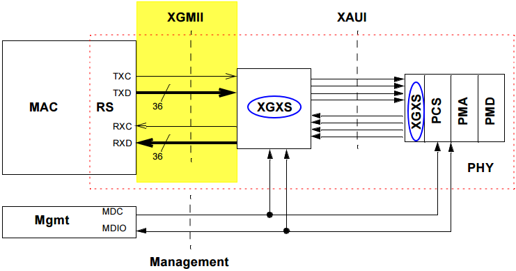
XGMII expands on the GMII signal set to accommodate the 10-fold increase in data rates:
- TXD[0..31] and RXD[0..31]: These are the transmit and receive data lines, respectively. XGMII uses a 32-bit wide data bus for both transmission and reception, allowing for rapid data transfer.
- TX_CLK and RX_CLK: These are the transmit and receive clocks, respectively. In XGMII, each operates at a frequency of 156.25 MHz, ensuring synchronization and timing for the 10 Gbps data rate.
- TX_CTRL[0..3] and RX_CTRL[0..3]: These control lines are used to convey control information alongside the data, such as start-of-packet and end-of-packet indicators.
- MDIO and MDC: Consistent with previous MII variants, these signals are used for the management and configuration of the PHY.
Operational Characteristics:
XGMII is designed to operate over relatively short distances, typically within a single piece of equipment or between adjacent devices in a rack. This is due to the challenges of maintaining signal integrity at such high data rates over longer distances.
Benefits of XGMII:
1. Ultra-High Speed: With a data rate of 10 Gbps, XGMII meets the demands of applications requiring immense bandwidth, such as cloud computing and high-performance computing clusters.
2. Efficient Data Transfer: The 32-bit wide data buses ensure rapid data transfer, making XGMII suitable for real-time applications and services.
3. Forward Compatibility: XGMII laid the groundwork for subsequent Ethernet standards, paving the way for even faster interfaces like 40GbE and 100GbE.
XGMII marked a significant milestone in the evolution of Ethernet technology. By achieving 10 Gbps speeds, it set a new benchmark for high-speed network communication. Its introduction played a pivotal role in accommodating the explosive growth of data traffic in the 21st century, reinforcing Ethernet's position as the backbone of modern communication networks. Understanding XGMII provides a glimpse into the relentless pursuit of speed and efficiency that characterizes the world of networking.
Comparison of Ethernet MII(Media Independent Interfaces)
| Interface | Data Rate | Data Bus Width | Clock Frequency | Pin Count | Description |
|---|---|---|---|---|---|
| MII | 100 Mbps | 4 bits | 25 MHz | 14 (data & control) + 2 (management) = 16 | Standard interface for Fast Ethernet. |
| RMII | 100 Mbps | 2 bits | 50 MHz | 6 (data & control) + 2 (management) = 8 | Reduced pin count version of MII. |
| GMII | 1 Gbps | 8 bits | 125 MHz | 16 (data) + 8 (control) + 2 (management) = 26 | Standard interface for Gigabit Ethernet. |
| RGMII | 1 Gbps | 4 bits | 125 MHz | 8 (data & control) + 2 (management) = 10 | Reduced pin count version of GMII. |
| SGMII | 1 Gbps | Serial | Variable, typically matching data rate | 2 (data) + 2 (control) + 2 (management) = 6 | Serial version of GMII, fewer pins. |
| XGMII | 10 Gbps | 32 bits | 156.25 MHz | 72 (data & control) + 2 (management) = 74 | Interface for 10 Gigabit Ethernet. |
Conclusion
The Ethernet PHY and its interfaces are pivotal in data communication. Each interface is designed for a specific purpose and environment, and understanding them is essential for effective network design and implementation. The choice and understanding of Ethernet PHY play a vital role in optimizing network performance and stability.