
ESP32S3 W5500 ETHERCAT SOES
ESP32S3 W5500 ETHERCAT SOES

WIZnet - W5500
x 1
요약
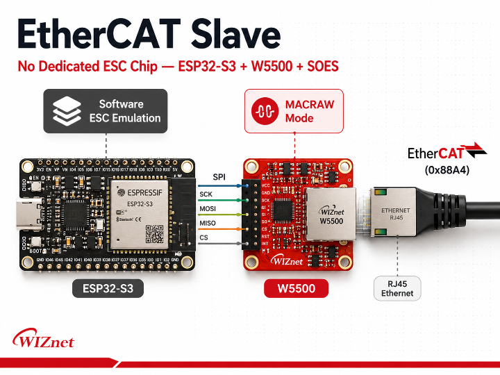
이 프로젝트는 ESP32-S3와 W5500 SPI 이더넷 컨트롤러, 오픈소스 SOES(Simple Open EtherCAT Slave) 스택을 결합해 전용 EtherCAT Slave Controller(ESC) 칩 없이 완전한 EtherCAT 슬레이브를 소프트웨어로 구현한다. W5500은 TCP/IP 오프로딩이 아닌 MACRAW 모드로 동작하며, ESC 에뮬레이션 전체는 ESP32-S3 펌웨어가 처리한다. Beckhoff TwinCAT 3과의 실제 통신이 검증되어, 전용 ESC 칩 없이도 산업용 EtherCAT 네트워크 진입이 가능함을 실증한 레퍼런스 설계다.
개요
EtherCAT은 산업 자동화 분야에서 가장 빠른 실시간 이더넷 필드버스 중 하나다. 그러나 EtherCAT 슬레이브 디바이스를 개발하려면 통상적으로 전용 ESC(EtherCAT Slave Controller) 칩이 필요하다. LAN9252(Microchip), AX58100(ASIX), ET1100(Beckhoff) 같은 ASIC이 EtherCAT 프레임을 하드웨어적으로 on-the-fly 처리하며, 이 칩 없이는 EtherCAT 슬레이브를 구현하기 어렵다는 것이 오랜 통념이었다.
이 프로젝트는 그 전제에 정면으로 도전한다. W5500 SPI 이더넷 컨트롤러를 raw 이더넷 채널로 활용하고, ESC 기능 전체를 ESP32-S3 펌웨어로 소프트웨어 에뮬레이션하는 방식으로, 전용 ESC 칩 없는 EtherCAT 슬레이브를 현실화했다. EtherCAT 프로토타이핑 비용과 진입 장벽을 낮추는 데 관심 있는 임베디드 개발자와 메이커에게 직접적인 참고 설계가 된다.
EtherCAT 슬레이브 구조 이해
EtherCAT은 표준 이더넷 프레임(EtherType 0x88A4)을 사용하지만, TCP/IP 스택을 거치지 않는 순수 L2 프로토콜이다. 마스터가 전송한 프레임은 각 슬레이브 노드를 통과하며 데이터를 읽고 쓴 뒤 되돌아온다.
일반적인 EtherCAT 슬레이브 구조에서 ESC 칩은 다음을 담당한다.
- EtherCAT 프레임을 하드웨어에서 on-the-fly 파싱
- FMMU(Fieldbus Memory Management Unit) 논리 주소 매핑
- DPRAM(Dual Port RAM) 기반 프로세스 데이터 교환
- SII EEPROM을 통한 슬레이브 식별 정보 저장
- AL(Application Layer) 상태 머신 지원
이 역할을 하드웨어 ASIC이 담당하기 때문에 마이크로컨트롤러의 부하와 무관하게 확정적인 실시간 응답이 가능하다. 이 프로젝트의 핵심 시도는 이 모든 기능을 소프트웨어로 에뮬레이션하는 것이다.
아키텍처
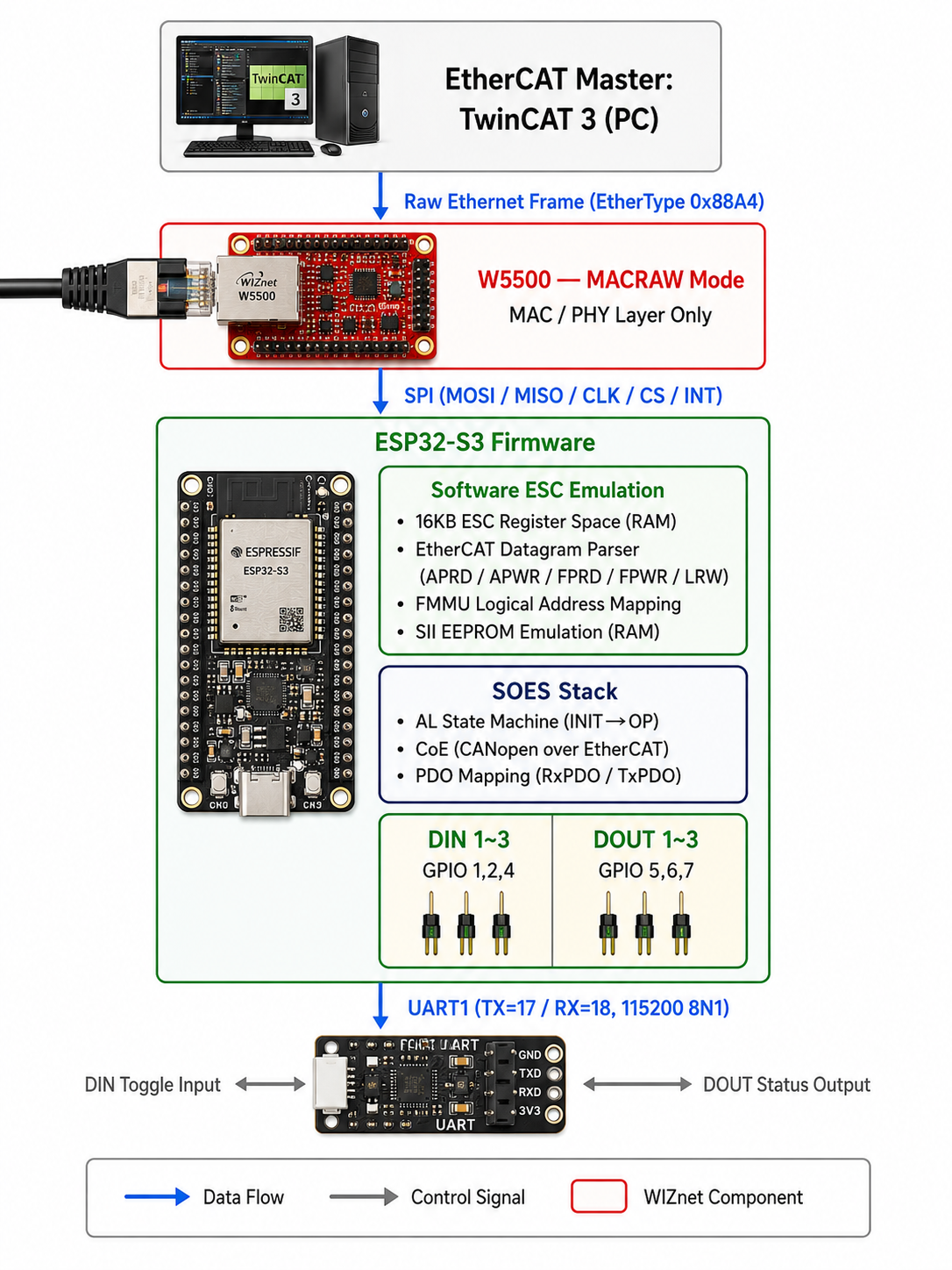
전체 흐름은 다음과 같다.
- TwinCAT 3이 EtherCAT 프레임(0x88A4)을 전송
- W5500이 MACRAW 모드로 raw 프레임을 수신, SPI를 통해 ESP32-S3에 전달
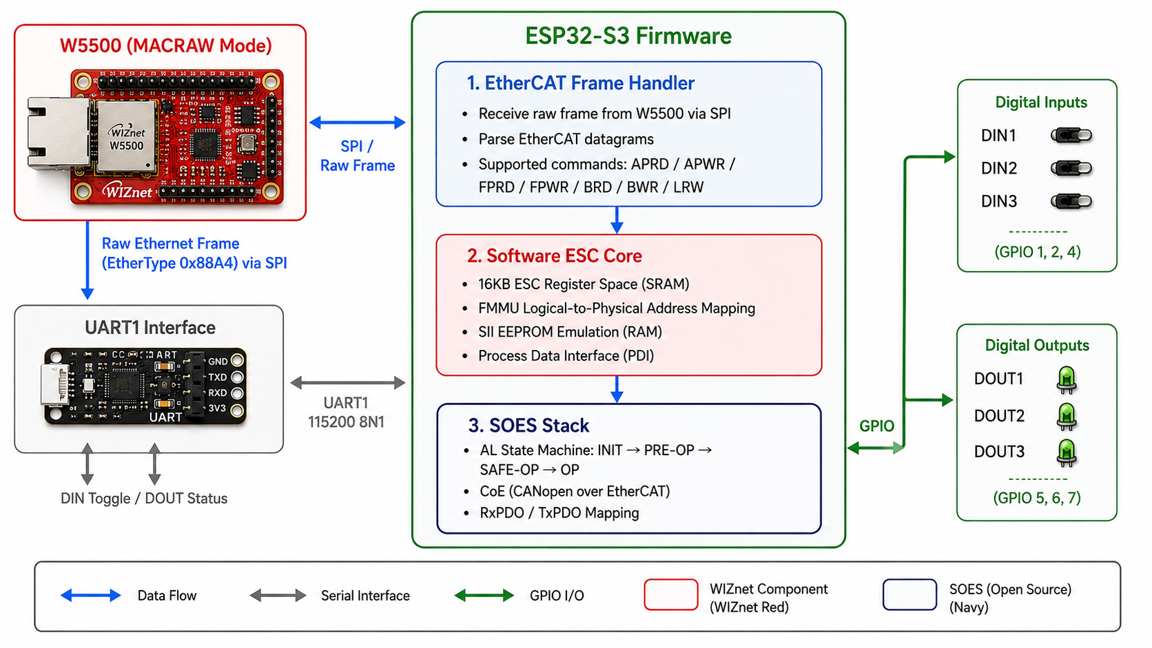
- ESP32-S3 펌웨어가 EtherCAT 데이터그램을 파싱하고 ESC 레지스터 에뮬레이션 수행
- SOES 스택이 AL 상태 머신 및 PDO/CoE 처리
- GPIO로 DIN/DOUT 제어, UART1로 시리얼 입출력 인터페이스 제공
W5500의 역할: MACRAW 모드
이 프로젝트에서 W5500은 TCP/IP 오프로딩 칩으로 동작하지 않는다. 이 점은 W5500을 활용하는 일반적인 IoT 프로젝트와 가장 중요한 차이점이다.
EtherCAT은 TCP/IP 스택을 거치지 않는 순수 L2 이더넷 프레임 기반 프로토콜이기 때문에, W5500의 하드웨어 TCP/IP 엔진은 이 경로에서 동작하지 않는다. 대신 W5500의 MACRAW 모드가 핵심 역할을 한다.
- MACRAW 모드: W5500이 소켓 추상화 없이 raw 이더넷 프레임을 그대로 수신·송신
- EtherCAT 프레임(0x88A4)이 W5500 MAC 레이어를 통과하여 SPI 버스로 ESP32-S3에 전달
- ESP32-S3 펌웨어가 프레임 내용을 직접 파싱하고, ESC 레지스터와 매핑
결과적으로 W5500의 역할 = MAC/PHY 인터페이스 제공 이며, ESC 에뮬레이션 로직 전체는 ESP32-S3 펌웨어에 위치한다. W5500이 이 구조에서 제공하는 실질적 가치는 다음과 같다.
- SPI 인터페이스만으로 이더넷 PHY/MAC 기능 획득
- ESP32-S3의 내장 이더넷 없이도 유선 네트워크 연결 확보
- 전용 ESC 칩(LAN9252 등) 대비 단가 절감 가능성
소프트웨어 ESC 에뮬레이션 상세
이 프로젝트의 기술적 핵심은 하드웨어 ESC가 담당하던 기능을 ESP32-S3 펌웨어로 완전히 재현한 것이다.
16KB ESC 레지스터 공간 (RAM 에뮬레이션) 실제 ESC 칩은 내부 DPRAM에 레지스터 공간을 보유한다. 이 프로젝트는 ESP32-S3의 SRAM에 16KB 크기의 레지스터 맵을 할당하여 동일한 구조를 소프트웨어로 구현했다. EtherCAT 마스터가 레지스터를 읽고 쓰는 접근 방식을 그대로 지원한다.
EtherCAT 데이터그램 파싱 수신된 raw 프레임에서 EtherCAT 데이터그램을 추출하고, 다음 커맨드 타입을 처리한다.
APRD/APWR: Auto-increment 물리 주소 읽기/쓰기FPRD/FPWR: Fixed 물리 주소 읽기/쓰기BRD/BWR: 브로드캐스트 읽기/쓰기LRW: Logical Read/Write (프로세스 데이터 교환)
FMMU 논리 주소 매핑 FMMU(Fieldbus Memory Management Unit)는 마스터의 논리 주소 공간과 슬레이브의 물리 주소 공간을 매핑한다. 이 프로젝트는 읽기/쓰기 타입 인식을 포함한 FMMU 매핑을 소프트웨어로 구현했다.
SII EEPROM 에뮬레이션 실제 ESC는 외부 I2C EEPROM(SII)에 슬레이브 식별 정보를 저장한다. 이 프로젝트는 물리적 EEPROM 없이 RAM에 SII 데이터를 에뮬레이션하여, 마스터의 EEPROM 읽기 요청에 응답한다.

SOES 스택 통합 및 I/O 구성
**SOES (Simple Open EtherCAT Slave)**는 OpenEtherCATsociety에서 개발한 오픈소스 EtherCAT 슬레이브 스택(GPLv2)이다. 이 프로젝트에서 SOES는 components/soes 디렉터리에 ESP-IDF 컴포넌트로 통합되어 있으며, 다음을 담당한다.
- AL 상태 머신: INIT → PRE-OP → SAFE-OP → OP 전이 관리
- CoE(CANopen over EtherCAT): 오브젝트 딕셔너리 기반 파라미터 교환
- PDO 매핑: TxPDO(슬레이브→마스터), RxPDO(마스터→슬레이브) 프로세스 데이터 처리
EtherCAT 오브젝트 구성은 다음과 같다.
| 인덱스 | 이름 | 방향 |
|---|---|---|
| 0x6000:01~03 | DIN1~3 | TxPDO (슬레이브 → 마스터) |
| 0x7000:01~03 | DOUT1~3 | RxPDO (마스터 → 슬레이브) |
ESI XML 파일(ESP32S3_SOES.xml)이 포함되어 있어, TwinCAT의 C:\TwinCAT\3.1\Config\Io\EtherCAT\ 경로에 복사하면 디바이스 스캔 시 "ESP32S3_SOES_W5500"으로 자동 인식된다.
UART1 인터페이스 (115200 8N1, TX=17/RX=18)는 개발·디버그 목적의 시리얼 채널이다.
1/2/3전송 → DIN1~3 토글 (입력 시뮬레이션)- TwinCAT이 DOUT 변경 시 →
DO:xyz형식으로 출력 (x/y/z = 0 또는 1)
비즈니스 가치 및 적용 시나리오
이 프로젝트는 EtherCAT 슬레이브 개발의 진입 방식을 재정의하는 시도다. 산업 현장뿐 아니라 연구·교육·프로토타이핑 환경에서 다양한 가치를 제공한다.
BOM 비용 절감 가능성 전용 ESC 칩(LAN9252 등)을 제거하고 W5500만으로 EtherCAT 슬레이브를 구성할 수 있다면, 대량 생산 시 단가 경쟁력이 높아진다. 단, 현재는 PoC 수준이며 상용화를 위한 추가 검증이 필요하다.
실제 적용 시나리오는 다음과 같다.
- 산업 자동화 프로토타이핑: TwinCAT 기반 PLC 시스템에 연결되는 커스텀 I/O 슬레이브 디바이스를 빠르게 개발
- 로봇 제어 시스템: EtherCAT 기반 서보 드라이브 또는 I/O 노드의 PoC 설계
- 교육·연구: 전용 ESC 칩 없이 EtherCAT 프로토콜 스택 동작 원리를 직접 실습
- 레거시 장비 연결: 기존 ESP32-S3 + W5500 기반 시스템에 EtherCAT 슬레이브 기능을 펌웨어 업데이트로 추가
한계 및 개선 방향
이 프로젝트가 EtherCAT 슬레이브 소프트웨어 에뮬레이션의 가능성을 실증했다는 점은 명확하다. 다만 PoC를 상용 설계로 발전시키려면 몇 가지 구조적 과제가 남아 있다.
현재 한계
- 실시간성 제약: 하드웨어 ESC는 EtherCAT 프레임을 on-the-fly로 처리해 수백 마이크로초 단위 사이클 타임을 보장한다. 소프트웨어 에뮬레이션은 SPI 전송 지연과 CPU 처리 시간이 추가되어 짧은 사이클 타임 구간에서 불확정성이 발생한다 [추정].
- Distributed Clocks(DC) 미지원: DC는 다수 슬레이브 간 수백 나노초 수준의 동기화를 제공하는 EtherCAT의 핵심 기능이다. 소프트웨어 에뮬레이션에서 이를 구현하는 것은 구조적으로 난이도가 높다 [추정].
- SPI 병목: W5500과의 SPI 통신 속도가 EtherCAT 사이클 타임의 상한을 제한한다.
- I/O 규모: 현재 3 DI/3 DO만 구현되어 있으며, 대규모 I/O 확장 시 성능 저하 여부는 미검증이다.
- 인증 부재: EtherCAT 상업 제품은 ETG(EtherCAT Technology Group) 공식 인증이 필요하다.
개선 방향
- SPI DMA 활용: ESP-IDF의 SPI DMA 기능을 적극 활용해 W5500과의 프레임 교환 지연 최소화
- FreeRTOS 태스크 우선순위 최적화: EtherCAT 프레임 수신 처리 태스크에 최고 우선순위를 부여해 지터(jitter) 감소
- MACRAW 인터럽트 드리븐 수신: W5500 INT 핀(GPIO 14)을 활용한 인터럽트 기반 수신으로 폴링 오버헤드 제거
- DC 지원 탐색: 소프트웨어 타임스탬프 기반 근사 구현 또는 ESP32-S3의 하드웨어 타이머 활용 가능성 탐색
FAQ
Q. TwinCAT 3 외 다른 EtherCAT 마스터와도 호환되나요? SOES 스택은 표준 EtherCAT 프로토콜을 따르므로 SOEM(Simple Open EtherCAT Master) 기반 마스터나 타사 EtherCAT 마스터와도 원칙적으로 호환 가능합니다. 단, 현재 검증된 환경은 TwinCAT 3뿐이며 다른 마스터와의 호환성은 별도 검증이 필요합니다.
Q. 전용 ESC 칩(LAN9252 등) 대비 성능 차이는 얼마나 되나요? 하드웨어 ESC는 EtherCAT 프레임을 on-the-fly 처리해 수백 마이크로초 이하의 사이클 타임을 지원합니다. 소프트웨어 에뮬레이션 방식은 SPI 전송 및 CPU 처리 시간이 추가되어 동일한 실시간성을 보장하기 어렵습니다. 성능 민감 응용(고속 서보 제어, DC 동기화 필요 시스템)보다는 저속 I/O, 프로토타이핑, 교육 목적에 적합합니다.
Q. 이더넷 스위치를 통한 연결은 불가능한가요? 현재 구현은 TwinCAT NIC과 W5500 사이의 직접(P2P) 연결을 전제로 합니다. EtherCAT은 프로토콜 특성상 일반 이더넷 스위치를 거치지 않고 직접 연결하는 것이 표준 구성이므로, 이는 이 프로젝트 고유의 제약이 아닌 EtherCAT 일반 규칙입니다.
Q. I/O를 3 DI/3 DO 이상으로 확장할 수 있나요? 아키텍처상 PDO 오브젝트 정의와 ESI XML 파일을 수정하면 I/O 확장이 가능합니다. 단, I/O 수가 늘어날수록 PDO 데이터 처리량과 ESC 레지스터 접근 빈도가 증가하므로, ESP32-S3의 연산 부하와 SPI 대역폭에 대한 추가 검증이 필요합니다.
Q. 상업용 제품에 적용하려면 어떤 절차가 필요한가요? EtherCAT 슬레이브를 상업 제품에 탑재하려면 ETG(EtherCAT Technology Group) 멤버십 가입 및 공식 적합성 테스트(CTT)를 통한 인증이 필요합니다. 또한 SOES 스택이 GPLv2 라이선스이므로 상업 배포 시 라이선스 조건을 반드시 검토해야 합니다.
TL;DR
This project combines an ESP32-S3, a W5500 SPI Ethernet controller, and the open-source SOES (Simple Open EtherCAT Slave) stack to implement a fully functional EtherCAT slave entirely in software — no dedicated EtherCAT Slave Controller (ESC) chip required. The W5500 operates in MACRAW mode, not as a TCP/IP offload engine, while the ESP32-S3 firmware handles all ESC emulation logic. Tested and working with Beckhoff TwinCAT 3, this project serves as a reference design proving that entry into industrial EtherCAT networks is possible without a dedicated ESC ASIC.
Overview
EtherCAT is one of the fastest real-time Ethernet fieldbuses in industrial automation. Traditionally, building an EtherCAT slave device requires a dedicated ESC chip — ASICs like LAN9252 (Microchip), AX58100 (ASIX), or ET1100 (Beckhoff) that process EtherCAT frames on the fly in hardware. Without one of these chips, implementing a conformant EtherCAT slave has long been considered impractical.
This project challenges that assumption directly. By using the W5500 as a raw Ethernet channel and emulating the full ESC functionality in ESP32-S3 firmware, it delivers a working EtherCAT slave with no dedicated ESC chip. For embedded developers and makers looking to reduce BOM cost or explore EtherCAT prototyping without specialized silicon, this design offers a concrete and reproducible starting point.
Understanding EtherCAT Slave Architecture
EtherCAT uses standard Ethernet frames (EtherType 0x88A4) but bypasses TCP/IP entirely — it is a pure Layer 2 protocol. Frames sent by the master pass through each slave node in sequence; each node reads and writes its data as the frame moves downstream.
In a conventional EtherCAT slave, the ESC chip handles the following:
- On-the-fly parsing of EtherCAT frames in hardware
- FMMU (Fieldbus Memory Management Unit) logical address mapping
- DPRAM-based process data exchange
- Slave identification via SII EEPROM
- Application Layer (AL) state machine support
Because a hardware ASIC handles these functions, deterministic real-time response is guaranteed regardless of the application controller's load. The core challenge of this project is to replicate every one of these functions in software.
Architecture
The data flow works as follows:
- TwinCAT 3 sends an EtherCAT frame (EtherType 0x88A4)
- W5500 receives the raw frame in MACRAW mode and passes it to ESP32-S3 over SPI
- ESP32-S3 firmware parses EtherCAT datagrams and performs ESC register emulation
- SOES stack manages the AL state machine and handles PDO/CoE processing
- GPIO controls DIN/DOUT; UART1 provides a serial interface for debug and input simulation
Where W5500 Fits: MACRAW Mode
In this project, the W5500 does not act as a TCP/IP offload engine. This is the most important distinction from typical W5500-based IoT designs.
Because EtherCAT is a pure Layer 2 protocol that bypasses TCP/IP entirely, the W5500's hardwired TCP/IP stack plays no role in the EtherCAT data path. Instead, the project relies on the W5500's MACRAW mode — the key capability that makes this design possible.
- MACRAW mode: the W5500 sends and receives raw Ethernet frames directly, with no socket abstraction
- EtherCAT frames (EtherType 0x88A4) pass through the W5500's MAC layer and are delivered to ESP32-S3 over SPI
- The ESP32-S3 firmware parses frame contents directly and maps them to the emulated ESC register space
In this architecture, the W5500's role is to provide a MAC/PHY interface — nothing more. The full ESC emulation logic lives entirely in the ESP32-S3 firmware. The practical value W5500 contributes is:
- Ethernet PHY/MAC capability over a simple SPI interface
- Wired network connectivity without relying on ESP32-S3's built-in Ethernet
- A lower-cost alternative to dedicated ESC chips as a raw frame channel
Software ESC Emulation in Detail
The technical heart of this project is the complete firmware-level reproduction of functions normally handled by a hardware ESC ASIC.
16KB ESC Register Space (RAM emulation) A real ESC chip maintains its register map in internal DPRAM. This project allocates a 16KB block in ESP32-S3's SRAM to replicate the same register structure, supporting all read and write access patterns expected by an EtherCAT master.
EtherCAT Datagram Parsing The firmware extracts EtherCAT datagrams from incoming raw frames and processes the following command types:
APRD/APWR: Auto-increment physical address read/writeFPRD/FPWR: Fixed physical address read/writeBRD/BWR: Broadcast read/writeLRW: Logical Read/Write (process data exchange)
FMMU Logical Address Mapping The FMMU maps the master's logical address space to the slave's physical address space. This project implements FMMU mapping in software, including read/write type awareness for correct data routing.
SII EEPROM Emulation A real ESC stores slave identification data in an external I2C EEPROM (SII). This project eliminates the physical EEPROM by emulating SII data entirely in RAM, responding to the master's EEPROM read requests from memory.
SOES Stack Integration and I/O Configuration
SOES (Simple Open EtherCAT Slave) is an open-source EtherCAT slave stack developed by the OpenEtherCATsociety (GPLv2). In this project, SOES is integrated as an ESP-IDF component under components/soes and handles the following:
- AL state machine: manages transitions between INIT → PRE-OP → SAFE-OP → OP
- CoE (CANopen over EtherCAT): object dictionary-based parameter exchange
- PDO mapping: process data handling for TxPDO (slave → master) and RxPDO (master → slave)
The implemented EtherCAT object configuration is as follows:
| Index | Name | Direction |
|---|---|---|
| 0x6000:01~03 | DIN1~3 | TxPDO (Slave → Master) |
| 0x7000:01~03 | DOUT1~3 | RxPDO (Master → Slave) |
An ESI XML file (ESP32S3_SOES.xml) is included. Copy it to C:\TwinCAT\3.1\Config\Io\EtherCAT\ on your TwinCAT machine, reload device descriptions, and a device scan will automatically detect "ESP32S3_SOES_W5500".
The UART1 interface (115200 8N1, TX=17 / RX=18) provides a serial channel for development and debug:
- Send
1/2/3→ toggles DIN1~3 (input simulation) - When TwinCAT changes DOUT values → slave reports
DO:xyz(x/y/z = 0 or 1)
Business Value and Use Cases
This project redefines the entry path for EtherCAT slave development. Beyond the proof-of-concept itself, it opens practical value across prototyping, research, and cost-sensitive production environments.
BOM cost reduction potential Eliminating a dedicated ESC chip (e.g., LAN9252) and relying on W5500 alone as the Ethernet interface can reduce per-unit cost in volume production. This remains at PoC stage and requires further validation before commercial deployment.
Concrete use cases include:
- Industrial automation prototyping: Rapidly develop custom I/O slave devices that connect to TwinCAT-based PLC systems
- Robotics and motion control: Build EtherCAT-capable servo drive or I/O node prototypes without dedicated ESC hardware
- Education and research: Study EtherCAT protocol stack behavior hands-on, without investing in specialized ESC silicon
- Legacy system integration: Add EtherCAT slave capability to existing ESP32-S3 + W5500 designs via firmware update
Limitations and Future Improvements
This project makes a clear and valuable contribution: it proves that software ESC emulation on ESP32-S3 + W5500 is viable. Moving from a proof-of-concept to a production-ready design, however, requires addressing several structural challenges.
Current limitations
- Real-time constraints: A hardware ESC processes EtherCAT frames on the fly, guaranteeing cycle times in the sub-millisecond range. Software emulation introduces SPI transfer latency and CPU processing overhead, creating timing uncertainty at short cycle times [Inferred].
- No Distributed Clocks (DC) support: DC is EtherCAT's mechanism for synchronizing multiple slaves to sub-microsecond precision. Implementing DC in a software emulation layer is architecturally complex and is not currently supported [Inferred].
- SPI bandwidth ceiling: The SPI link between W5500 and ESP32-S3 limits the upper bound of achievable EtherCAT cycle times.
- Limited I/O scale: Only 3 DI/3 DO are currently implemented; performance under larger I/O configurations is unverified.
- No ETG certification: Commercial EtherCAT products require official conformance testing through the EtherCAT Technology Group (ETG).
Future improvements
- SPI DMA: Leverage ESP-IDF's SPI DMA support to minimize frame transfer latency between W5500 and ESP32-S3
- FreeRTOS task priority tuning: Assign the highest task priority to the EtherCAT frame reception handler to reduce jitter
- Interrupt-driven MACRAW reception: Use the W5500 INT pin (GPIO 14) for interrupt-based frame reception, eliminating polling overhead
- DC support exploration: Investigate approximate DC implementation using software timestamps or ESP32-S3 hardware timers
FAQ
Q. Does this work with EtherCAT masters other than TwinCAT 3? The SOES stack follows the standard EtherCAT protocol, so compatibility with SOEM-based masters and other third-party EtherCAT masters is expected in principle. However, TwinCAT 3 is the only master verified so far. Testing with other masters is recommended before deployment.
Q. How does performance compare to a dedicated ESC chip like LAN9252? A hardware ESC processes EtherCAT frames on the fly and supports cycle times well below 1ms. Software emulation adds SPI transfer and CPU processing delays, making it difficult to match the same real-time guarantees. This design is best suited for low-speed I/O, prototyping, and educational use rather than high-speed servo control or applications requiring DC synchronization.
Q. Is an Ethernet switch required, or must it be a direct connection? The current implementation requires a direct (P2P) connection between the TwinCAT NIC and the W5500 — no standard Ethernet switch. This is consistent with general EtherCAT topology rules, not a limitation specific to this project.
Q. Can the I/O be expanded beyond 3 DI / 3 DO? Architecturally, yes — modifying the PDO object definitions and the ESI XML file allows I/O expansion. As the number of I/O points grows, PDO data volume and ESC register access frequency increase, so additional benchmarking of ESP32-S3 CPU load and SPI bandwidth is recommended.
Q. What is required to use this in a commercial product? Commercial EtherCAT slave products require ETG membership and passing the official Conformance Test Tool (CTT). Additionally, the SOES stack is licensed under GPLv2 — review the license terms carefully before any commercial distribution.