
Autonomous Robot Car with Lidar & Motion Tracking: A Fusion of Obstacle Avoidance and Precision Path
Autonomous Robot Car with Lidar & Motion Tracking: A Fusion of Obstacle Avoidance and Precision Path Planning

WIZnet - W5500
x 1
자율 주행 기술의 핵심은 "현재 위치 파악(Localization)", "주변 환경 인식(Perception)", 그리고 "경로 계획(Path Planning)"의 완벽한 조화에 있습니다.
이번에 소개할 프로젝트는 Texas Instruments의 C2000 Delfino LaunchPad를 메인 컨트롤러로 사용하여, Lidar로 장애물을 실시간 감지하고, 개선된 A* 알고리즘으로 최적 경로를 계산하며, 외부 모션 트래킹 시스템으로 정밀한 위치 제어를 구현한 로봇 자동차 프로젝트입니다.
복잡한 임베디드 시스템에서 센서 데이터 처리와 알고리즘, 그리고 네트워크 통신이 어떻게 유기적으로 결합되었는지 상세히 분석해 보겠습니다.
1. 프로젝트 개요 (Overview)
이 프로젝트의 목표는 단순합니다. "출발지에서 목적지까지, 트랙 위에 무작위로 놓인 장애물을 피해 도달하라." 하지만 이를 구현하기 위한 과정은 결코 단순하지 않습니다. 로봇은 끊임없이 변화하는 환경을 인식하고, 자신의 위치를 오차 없이 파악해야 하며, 가장 효율적인 길을 계산해내야 합니다.
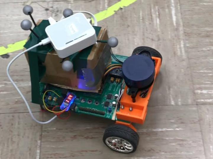
- 주요 하드웨어: TI LAUNCHXL-F28379D, YDLIDAR X2, WIZnet W5500
- 핵심 기술: Lidar 매핑, A* 경로 탐색(대각선 이동 포함), Optitrack 모션 트래킹 연동
2. 핵심 기술 분석 (Key Technologies)
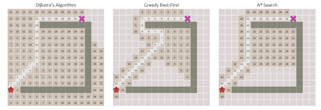
💡 Step 1: 세상을 보는 눈, Lidar 센서와 맵 생성
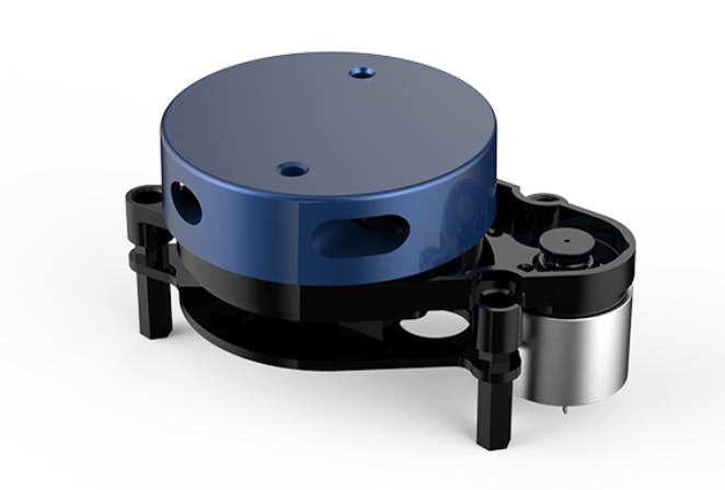
로봇의 '눈' 역할은 360도 스캐닝이 가능한 YDLIDAR X2가 담당합니다.
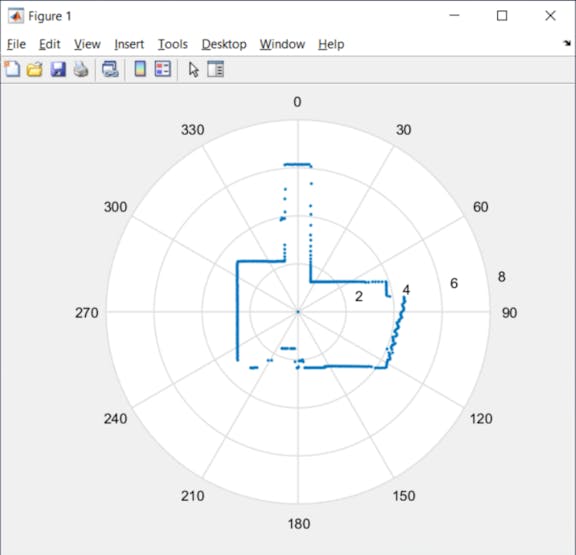
- 데이터 수집 및 변환: Lidar는 거리(Distance)와 각도(Angle)로 이루어진 극 좌표계 데이터를 전송합니다. 로봇은 자신의 현재 위치(Pose)를 기준으로 이 데이터를 전역 좌표계(Global View)로 변환합니다.
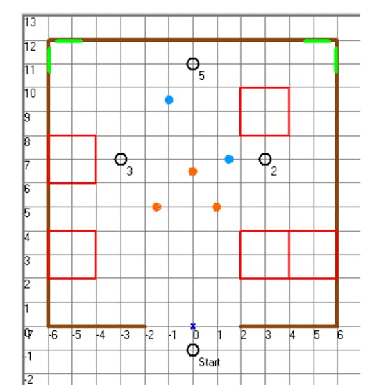
- 그리드 맵핑(Grid Mapping): 주행 트랙을 12x12 크기의 격자(Grid)로 나누고, 장애물이 감지된 위치의 격자에 'x' 표시를 남깁니다. 이때, 센서의 노이즈를 방지하기 위해 로봇과 지나치게 가까운 데이터는 필터링하여 맵의 신뢰도를 높였습니다.
이 과정을 통해 로봇은 인간이 지도를 보는 것처럼 트랙의 장애물 배치를 실시간 이진(Binary) 배열로 기억하게 됩니다.
🧠 Step 2: 최적의 길 찾기, 진화된 A*(A-Star) 알고리즘
장애물 위치를 파악했다면, 이제 목적지까지 가는 길을 찾아야 합니다. 이 프로젝트에서는 대표적인 경로 탐색 알고리즘인 A*(A-Star)를 사용하되, 효율성을 위해 이를 개량했습니다.
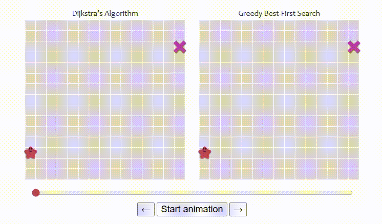

- 대각선 이동 허용: 일반적인 격자 기반 A* 알고리즘은 상하좌우 4방향 이동만 고려하는 경우가 많습니다. 이 프로젝트에서는 대각선 이동을 허용하여 로봇의 움직임을 더 부드럽게 만들고 이동 거리를 단축했습니다.
- 조건: 대각선으로 이동하려는 방향의 인접한 수평/수직 격자가 모두 비어있을 때만 이동을 허용하여 충돌을 방지합니다.
- 비용 함수(Cost Function) 최적화:
- 휴리스틱(Heuristic): 맨해튼 거리(Manhattan Distance) 대신 유클리디안 거리(Euclidean Distance) 공식을 적용하여 실제 물리적 거리에 가까운 추정치를 사용했습니다.
- 이동 비용: 수평/수직 이동 비용은 1, 대각선 이동 비용은 $\sqrt{2}$로 설정하여 계산의 정밀도를 높였습니다.
** Introduction to the A* Algorithm(https://www.redblobgames.com/pathfinding/a-star/introduction.html)
📍 Step 3: "나는 어디인가?", 모션 트래킹과 하이브리드 통신
로봇 바퀴의 회전수만으로 위치를 추정하는 데드 레코닝(Dead Reckoning) 방식은 바퀴의 미끄러짐 등으로 인해 시간이 지날수록 오차가 누적됩니다. 정밀한 주행을 위해 이 프로젝트는 Optitrack 모션 트래킹 시스템을 도입했습니다.
- Ground Truth 확보: 외부 카메라 기반의 Optitrack 시스템이 로봇의 정확한 $x, y, \theta$ (위치 및 방향) 데이터를 실시간으로 측정합니다.
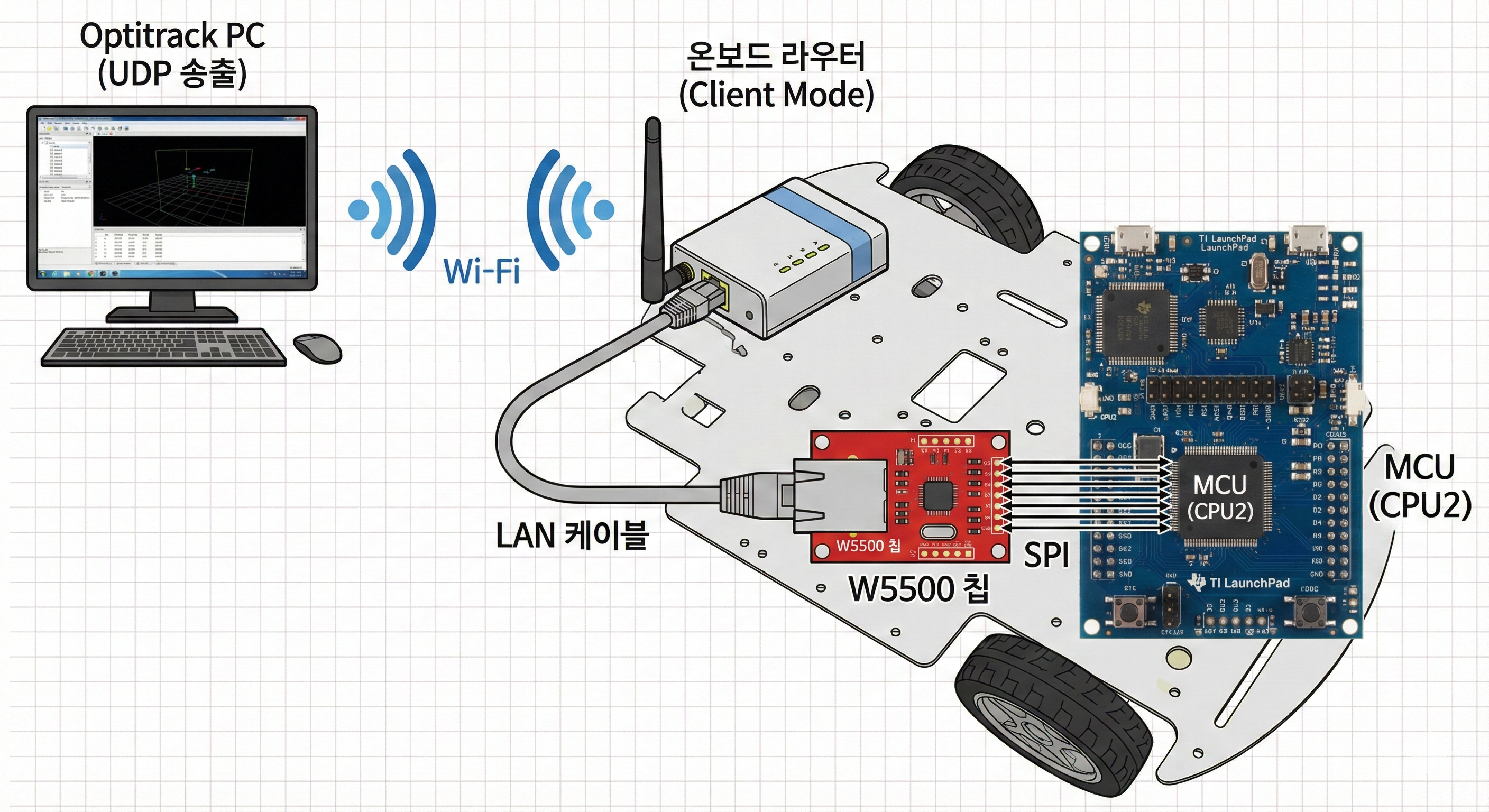
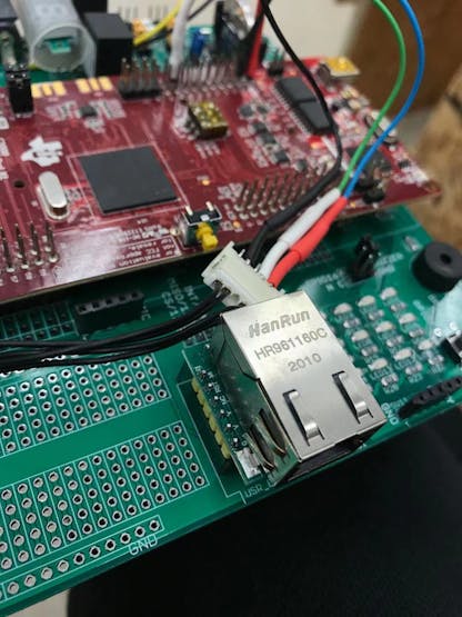
- W5500과 공유기를 활용한 연결 구조: 유선 칩인 W5500을 무선 환경에서 사용하기 위해 **'클라이언트 모드'로 설정된 소형 공유기(Router)**를 로봇에 탑재했습니다.
- 공유기가 외부 Wi-Fi 신호(위치 데이터)를 무선으로 수신합니다.
- 수신된 신호는 LAN 케이블을 통해 유선으로 W5500에 전달됩니다.
- W5500은 UDP 프로토콜을 통해 지연 없이 데이터를 MCU로 넘깁니다.
이러한 구조 덕분에 로봇은 물리적인 선의 제약 없이 자유롭게 움직이면서도, W5500의 안정적인 통신 성능을 활용할 수 있었습니다.
3. 시스템 아키텍처: 듀얼 코어의 활용 (Implementation)
이 프로젝트의 백미는 TI F28379D MCU의 듀얼 코어(Dual-Core) 성능을 십분 활용했다는 점입니다.
- CPU 1 (주행 제어): 모터 제어, Lidar 데이터 처리, A* 알고리즘 수행, 로봇의 움직임 제어 등 핵심 주행 로직을 담당합니다.
- CPU 2 (통신 전담): Optitrack 시스템과의 UDP 통신을 전담합니다. 네트워크 데이터 수신은 대기 시간이 발생할 수 있는 작업이므로, 이를 별도 코어에 할당하여 CPU 1이 주행 제어에만 집중할 수 있도록 격리했습니다.
IPC (Inter-Processor Communication): CPU 2가 수신한 위치 데이터는 IPC 레지스터를 통해 실시간으로 CPU 1에게 전달되어 주행 알고리즘에 즉각 반영됩니다.
4. 결론 (Conclusion)
이 프로젝트는 단순히 로봇을 움직이는 것을 넘어, 인식(Lidar) - 판단(A) - 행동(Motion Control)이라는 자율 주행의 3단계를 저비용 하드웨어로 충실히 구현해냈습니다.
특히 유선 이더넷 칩인 W5500에 무선 공유기 브릿지를 연결하여 외부의 정밀 위치 정보를 끌어오고, 이를 듀얼 코어 아키텍처로 효율적으로 처리한 점은 임베디드 시스템 설계의 훌륭한 모범 사례라 할 수 있습니다.
The holy grail of autonomous driving technology lies in the perfect harmony of Localization, Perception, and Path Planning.
This project showcases an autonomous robot car built on the Texas Instruments C2000 Delfino LaunchPad. It successfully integrates real-time obstacle detection using Lidar, optimized path calculation via an enhanced A* algorithm, and precision position control through an external motion tracking system.
Let’s dive into how sensor data processing, algorithmic logic, and a unique network architecture come together in this embedded system.
1. Project Overview
The goal is simple yet challenging: "Navigate from a starting point to a destination on a track while avoiding randomly placed obstacles."
To achieve this, the robot must continuously perceive its changing environment, determine its exact location without error, and calculate the most efficient route.
- Main Controller: TI LAUNCHXL-F28379D (Dual-Core MCU)
- Sensors: YDLIDAR X2 (Perception), Optitrack System (Localization)
- Connectivity: WIZnet W5500 (Ethernet Controller)
2. Key Technologies
💡 Step 1: Perception – The Eyes of the Robot (Lidar & Mapping)
The YDLIDAR X2 serves as the robot's eyes, performing 360-degree laser scanning.
- Data Transformation: The Lidar transmits data in polar coordinates (Distance, Angle). The robot converts this into a Global View based on its current pose.
- Grid Mapping: The track is divided into a 16x11 Grid. When an obstacle is detected, the corresponding grid cell is marked with an
'x'. To ensure reliability, data points too close to the robot (potential noise) are filtered out.
Through this process, the robot creates a real-time binary map of the track, similar to how a human reads a map.
🧠 Step 2: Planning – Enhanced A* Algorithm
Once obstacles are mapped, the robot needs a path. This project utilizes the A (A-Star) algorithm*, optimized for this specific environment.

- Diagonal Movement: Unlike standard grid-based A* which often restricts movement to 4 directions (Up/Down/Left/Right), this implementation allows diagonal movement. This results in smoother trajectories and shorter distances.
- Condition: Diagonal moves are only permitted if both adjacent horizontal and vertical cells are clear to prevent collision with corners.
- Cost Function Optimization:
- Heuristic ($h$): Switched from Manhattan Distance to Euclidean Distance to represent physical reality more accurately.
- Travel Cost ($g$): Defined as $1$ for horizontal/vertical moves and $\sqrt{2}$ for diagonal moves for precise calculation.
📍 Step 3: Localization – Hybrid Communication with W5500
Relying solely on wheel encoders (Dead Reckoning) leads to accumulated errors over time due to wheel slip. To solve this, the project uses the Optitrack Motion Tracking System to provide "Ground Truth" data ($x, y, \theta$).
A key innovation here is the hybrid communication architecture used to deliver this data to the mobile robot.

- Ground Truth Transmission: The external PC broadcasts the robot's precise location via Wi-Fi.
- Wireless Bridge: A small router mounted on the robot is set to 'Client Mode'. It captures the Wi-Fi signal.
- Wired Conversion: The router passes the data through a LAN cable to the W5500 Ethernet chip.
- Processing: The W5500 handles the TCP/IP stack via hardware and passes the data to the MCU.
This setup allows the robot to move freely without physical tethers while leveraging the stability and ease of use of the W5500 hardwired Ethernet chip.
3. System Architecture: Leveraging Dual-Core Power
To maximize the performance of the TI F28379D MCU, tasks were distributed across its two cores.
Core | Role & Function |
|---|---|
CPU 1 | [Main Control] Motor PID control, Lidar data processing, A* algorithm execution, and path following. |
CPU 2 | [Communication] W5500 initialization, UDP Server management, and Optitrack packet reception. |
IPC (Inter-Processor Communication): Since network reception can be blocking or latency-prone, it is isolated on CPU 2. Once CPU 2 receives the location data, it instantly transfers it to CPU 1 via IPC registers. This ensures the main control loop on CPU 1 runs uninterrupted.
4. Conclusion
This project goes beyond simple remote control, successfully implementing the three pillars of autonomous driving: Perception (Lidar), Planning (A), and Control (Motion Tracking)* using cost-effective hardware.
Particularly, the architectural choice to combine a wired Ethernet chip (W5500) with a wireless router bridge to overcome hardware limitations, along with the efficient use of Dual-Core processing, serves as an excellent reference for embedded system developers solving complex integration problems.
-
Final Code

-
Schematics