
DigitalTwin For STM32
n this video tutorial we will present an interesting application with the aim of simulating in a virtual environment, using the FactoryIO software, a process of
COMPONENTS
Hardware components


WIZnet - W5500
x 1
PROJECT DESCRIPTION
Hello In this video we will address a very interesting topic, we will run a simulation of a process already known from previous videos in our tutorial area, which is the box conveyor elevator, we will integrate this process in a virtual environment using the tool Factory ayu as if it were a digital Twin and we will use the Buster CP mod communication within this simulator, this process running in a virtual environment and our me controller stm32 f103 we will develop the application
control that has already been covered in one of the topics of our video classes in the past in our tutorial area, right, another topic that was covered was the communication interface there TCP clight and More specifically the protocol there modus TCP clight using the w5500 shield of the w5500 together with the f103 controller from the Blue piu plaque, so with very cheap resources that we have here at hand, we will insert all the control logic into my controller, right? All the state machines, the state machines of this
process As said there, once again already covered in one of our previous videos, right, just like the Buster promod library covered in another video, we are going to integrate this solution into the controller, use internet communication there, but specifically there with the mod Bush TCP protocol, there in the clite option and we will communicate as a mod bus server through the physical environment, right, Ethernet, which will be running in a virtualized environment within the software Factor using software is a very interesting resource for you to use in your studies
in your proofs of concept So that's it. It's very interesting because you can virtualize your process that you want to automate and through very low cost resources like this myth controller and this shield you will be able to execute your code, right? insert your non-controller control logic there and prove the concept of this, so stay tuned in the next few minutes as we will show in practice how this interesting thing works, very well, let's do a
demonstration of how this application works, remembering once again that the concept of the state machine, the concept of software structuring behind this application, is available in our tutorials area, there is a video there dedicated to the topic, there is also a video dedicated there to the modus application TCP client, right, an application using the w5500, right? And also there, I have the stm32f63 controller, all two videos available on our platform, which we are going to do once again. Remembering to use this application
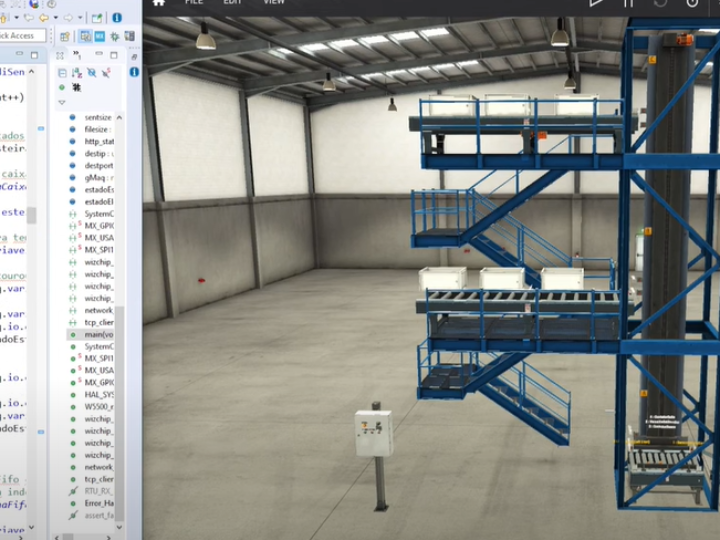
mod bus TCP Clint and attach this application integrate this application into the control state machine of this box transport elevator so if we look here on the right side we have the Factor screen where we have already dimensioned our application which is here basically the elevator, the conveyors, lower, upper, some boxes positioned here on the respective conveyors, their actuators, their conveyor sensors, the elevator floor level indication sensors, as well as the elevator's internal conveyor sensor or
be it that application that we already showed in the video, right in that video tutorial, implemented in practice here in a model, right, a simulated model, this is very interesting, let's use this powerful feature of this tool, a tool developed very much for the industrial automation area, so what are we going to do? is to use these resources, right, from this tool in communication with a microcontroller and for this purpose, we implemented this application for this controller, as we will quickly show, right after this,
In this simulation video we implement here the modus TCP application, we use some resources for communication for the modus TCP application. Then sending bits and receiving bits, right, so we're going to force some coils to read some inputs and with that we're going to establish communication between the stm32 f103 controller and the simulated application in Factor Areal, this is basically the same, we are applying a digital swing to this controller, which has a very low cost, right?
We are here bringing several possibilities to developers, people who like working with this theme, using very low cost resources. This is a very interesting approach to the theme, so we have it here within Factory, or this application. I will make available in this video, in the part of the video description, an Android link, right? This OneDrive contains all those projects in the tutorial area of my channel and I will be adding the software in this tutorial area.
complete for the micro controller that was developed in the stm32 Cube, right there and also this application of the elevator for transporting boxes to the factory. So you will basically open these files, right, run and do simulations and, of course, there are a number of videos on the internet covering the Factor tool, how to work with this with this modeling, insert actuators, sensors, that is, you modify it, adapt it according to your system, according to your machine and later, of course, work on top of the machines.
States and the concept and develop your application for me controller so basically here it is as if it were our real plant in a simulation environment and here is the software application that we developed to glue this process so here on the left side later we will address There are already the state machines that we implemented in that video, we explain in detail the concept for applying the box transport elevator, so it's all implemented and running, this application doesn't control me as well as it could be one
application running on the PLC, for example, so we use a controller, a cheap resource easily available on the market, with an ethernet card based on the chip, then Snap, the w5500, also very low cost, so we implemented a Buster CP client mod in this application, in this application. Half a controller, right, and we're communicating with the simulator, so we developed our plant here and we control our plant from the applied software installed, downloaded, I'm not a controller, that's a lot, right, I'll show you here, we can
debug, right, do navigation line line here in the code debug variables, this is possible, right? In the resource that the tool brings us to this micro controller available here and here on the right side Factor It's me Okay, I'm not going to go into the details once again Here's how you develop here on top of the Factor, here you modify the position of objects, etc., the tool allows three-dimensional navigation, as you can see, the very comprehensive resource, we have an option here, right, for drivers file
drivers inside the Factor is me and here look how interesting, right in this application we are going to work here with modus TCP ep server So we are going to apply here the modus Buster CPI series we are going to insert some inputs and outputs into this application, right so basically here in the Factory editor or we can look for our sensors here for example So the actuators for example here we have the contactor so that the elevator goes up so that the elevator goes down so basically the names the tags you click here on the Tag right on the
actuator here and you can come here to the tool and modify the name according to your needs here with your application so we did that we have already developed here for this process all the tags to communicate with the controlling monkey are all already there is identified, we go here to the drivers option and if you notice, we have already mapped entries 0 to 8 here, I will show later that we are inserted there, we add the Buster application that exists in the previous video, we add new features, right?
We have the resources to work with communication, reading up to 16 input bits and writing up to 16 output bits, apart from the registers part that already existed in the previous implementation and of course you know the protocol by getting the library you can easily adapt this library to work with many more input output bits for the application, this tool is very interesting, right? We have already mapped inputs zero to input eight and allocated these respective inputs.
respective imputs their respective sensors so for example the reset button on the lower conveyor belt the button to reset the upper conveyor belt the button to reset the elevator the lower Ester sensor on the lower floor of the upper conveyor elevator on the upper floor of the elevator internal conveyor belt of the elevator and the unloading floor are all already imputed, you can observe here the sensor of the upper lower belt and of the elevator, it is activated, right, it is a normally closed sensor, so if we observe here
I'm going to give you an approximate figure, so we can already observe here, the reflective mirror and the sensor activated from both the lower conveyor belt, the upper conveyor belt and the discharge conveyor belt below, so this is a concept since we're addressing it, right? quite interesting, you can already have a good understanding of the tool's features. So what we're going to do here is basically initialize, but look how interesting, before that, here are Drivers for clps and the closest to our reality for
implementing the microcontroller that made it much easier for us to adopt this process was buster's mod application CPP server So I'm working with a microcontroller as a client and the simulator, this simulator, right in this plant, right, this process as a server And then, of course, you have to designate the correct IP accordingly with yours with your network, right, basic thing, port 502 for TCP mode here is the slave identifier so in our case we use identifier one And look how interesting the digital outputs and digital inputs we go
work with inputs and coils, so of course if we had analog variables in this process we could work with input Regis and holding registers and our library was developed way back in the MOD Buster tutorial, it already includes options for reading and writing registers so if you are working with analog variables you already have this resource available in the library and you can make this interface between microcontroller and simulator so I will basically start like you
you can observe the IP is already here it is already in the process of communicating with my controller what am I going to do now you can observe the mats are static and we are going to go here basically now initialize here by pressing play but before that I will go into mode debug mode in the controller so I go here to the run the bug option we are going to go into debug mode here with my controller let's wait it is compiling it will communicate with my controller let me connect the cables here otherwise the
We won't be able to do this communication, of course we wait here for a while for the process and let's observe the result Ok, we entered debug mode so basic knowledge of ours there in the micro controller in development so here we can already observe the states of some variables for example look how interesting the elevator is at the moment in the state wait for FIFA in this people recap in the video we explain the state machines for this for this application for this process is
precisely this is the first state and in the case of the two treadmills it is in the waiting box state we have the application paused here in the first line so what we are going to do is basically initialize the simulator so we apply it here in the Run option, you can see here that it is already it is already running because Possibly we already had it in our process this is very interesting this contactor actuated So so that we can avoid this I'm going to restart but before restarting Look how interesting we are going
basically for the driver to initialize the driver so we can see that now all the outputs are off it won't come up our controller is currently standing here static, right At the beginning of the program before we proceed here with the execution so we are already communicating I'm going to basically restart the simulation here, so all the conveyors, the boxes are positioned, the elevator on the unloading floor, I purposely placed the boxes in different positions, right, with spacing between them, if we
observe the box on the upper floor It is a little ahead of the box on the lower floor so it is expected that in our process in our application that was developed, the elevator will initially seek the upper floor because this box will reach its sensor first, this will register in our application fifo and here at this moment we will initialize that the controller, its execution, will look for the upper box. So at this moment all the logic applied to the micro controller is controlling this process alone And look
How interesting now he goes to the lower floor, right inside our From the Logic of our Fifa, the box will arrive, he will stop, he will go downstairs, he will unload Look how interesting, I'm going to provoke him, now I'm going to save him, he will arrive on the upper floor to get the next box and when he has Transporting the box inside the elevator I will suspend the control suspend the controlling application Look how interesting at this moment the sensors stop acting and we no longer have control over the application itself
here if we zoom in here at Factory ayou we will observe here that the rollers are rotating I will even enable the audio so you can see how realistic this tool is, okay I will enable the audio you will observe now it's the noise here from our treadmill I will move away from the treadmill and you will notice that the noise decreases, it is very very interesting, okay, so if I order it to run here again here our process stopped because it was waiting for the box to arrive here so what can we do for example
is to force this actuator as if it had reached the box you can see that the conveyor belt will stop rotating So that's it It's very interesting, right, the process, right, the dynamics of this process, I hope you enjoyed it, now I'm going to go into what's going on a little bit. it was made within the controller software to enable communication, this adaptation in the mod bus library, right, to communicate here with Factor for this simulator and that's perfect, so let's go here to the middle point c, right, so this code here is part
of it, right, we already covered this subject in the video about the Buster mod, right, applied to the w5500, so we already have this entire approach presented here, right, all the part here, right, about the downtime to generate alarms, right, It's all the software structures of our box conveyor elevator control state machine, of the box transport system, this was also covered in a video that we made available here on our platform, so I advise that if you haven't watched it
Go over these videos, what we basically did here, right? I'm going to download them here a little Right at the beginning of the main loop, right? I used basically that code presented in the video lesson about the Mod Buster CP client. The only difference is that now, right? I applied it right, here, right, I developed a function here within the library for reading discrete inputs and also a function for writing multiple ones, in our previous video, in our previous application, we had developed it here for this library
just reading and writing registers, right, for analog variables, cool, we've added it here now, so a new feature in this library for reading discrete inputs and also writing coios. So if we observe basically what we have here is assembly, not raw protocol right about the protocol here mod bus TCP so we have here download here the formation of this protocol I advise you to look for those bibliographies that we have already covered on the website that we have already covered in the video on the subject, right And here
basically what we did is insert what we did was insert this new protocol here for reading and writing discrete Boolean signals for both things and inputs so that's what we have here, okay? So what do we do? what we do here is to set up the protocol to apply these fungi that are codes here from our infamous modus, so what we did here is reading the discrete inputs, so we send this request, right from here, this one is the client for the simulator that is the server the simulator for
In turn, he will respond and when he has a response, we perform this reading task here in this reading cup, right? And here he will return the values of his inputs. So what we are doing basically, right? So there is already a union here, right? a Union type for the Coil input that we will bitch From this instruction we will request via the Bush TCP mod, right via the Buzz ball protocol and ethernet implementation there, right? our
server in this case is the simulator so what we are requesting from the simulator the state of its digital inputs from the Sensors of our simulation process and all the values of these inputs which in our case we observed there were nine inputs all these nine inputs they will be stored here in this Word of our Coil input and then we will unravel bit by bitchest World so the first bit is the lower belt reset button, the second bit is the lower belt box sensor and
see that I use logic, not inverted logic, right, I invert the signal Because because there we have a normally closed NC sensor, then I invert it to meet my logic that was developed previously and I do this bit by bit, right, bit three here goes to the elevator sensor and if we open the factory or this is really respecting the distribution that we put there see I'm just going to enlarge here the hear me button lower sensor Ester lower lower floor so it's following this
Very cool distribution, right? That's it, we're going to our state machine, which was also discussed and presented in that video lesson, the only difference here guys is that I removed the part that communicated with the OLED display, now I'm not using the allerio display, I just removed that part of communication, the rest I won't go into details because this is very well explained in that video and full of comments here in our software too and it comes from the digital outputs in the digital outputs part
What we do is take the structure and the members of the structures that correspond to our actuators, so for example the counter of the motor of the lower belt, the contactor of the upper belt, of the elevator for upward descent movement and also of the elevator belt and I I attribute this to each of the Bits of our Coil output if we come here o It's following the same structure as the actor lower conveyor upper conveyor descends rises and also the elevator conveyor belt follows this order and then we execute the new functionality here
which was inserted, right, developed for our mod bus library dcp which is the writing of multiple coiolios and in this case we are writing 16 bits up to 16 bits remembering you can modify this structure to write more bits if you have more inputs or more outputs here it is just an initial concept so you can explore this resource and adapt it to your needs and the size of your projects. I hope you enjoyed this video and see you next time
Documents
Comments
Write