



Watchdog Timer (WDT) Explained: Principles, Classifications & Beginner Practical Guide
Beginner‑friendly introduction to watchdog timer WDT, covering working principles, classification and real‑world embedded application scenarios.
In single‑chip‑microcontroller systems, operating environments are usually complex and susceptible to interference from external electromagnetic fields. The following problems may occur:
Corrupted register and memory data External electromagnetic interference can unexpectedly modify data stored in registers or memory, disrupting normal program execution.
Incorrect program counter Data corruption or interference may cause the program counter to jump to unintended memory locations, making the CPU execute wrong instructions.
Infinite loop lock‑up If the program counter branches to an invalid address, the program may enter an unrecoverable infinite loop and the system hangs.
System halt When the program gets stuck or fails to execute valid instructions, the whole system stops and cannot carry out expected operations.
To mitigate these issues, the Watchdog Timer (WDT) plays a critical role. A watchdog timer is a hardware timer used to monitor system operation. Its primary purpose is to prevent system lock‑ups and infinite loops. When software runs normally, the watchdog timer must be reset periodically. If a system fault occurs and the watchdog is not reset in time, the timer triggers a system reset or other predefined actions to restore the system to a functional state.
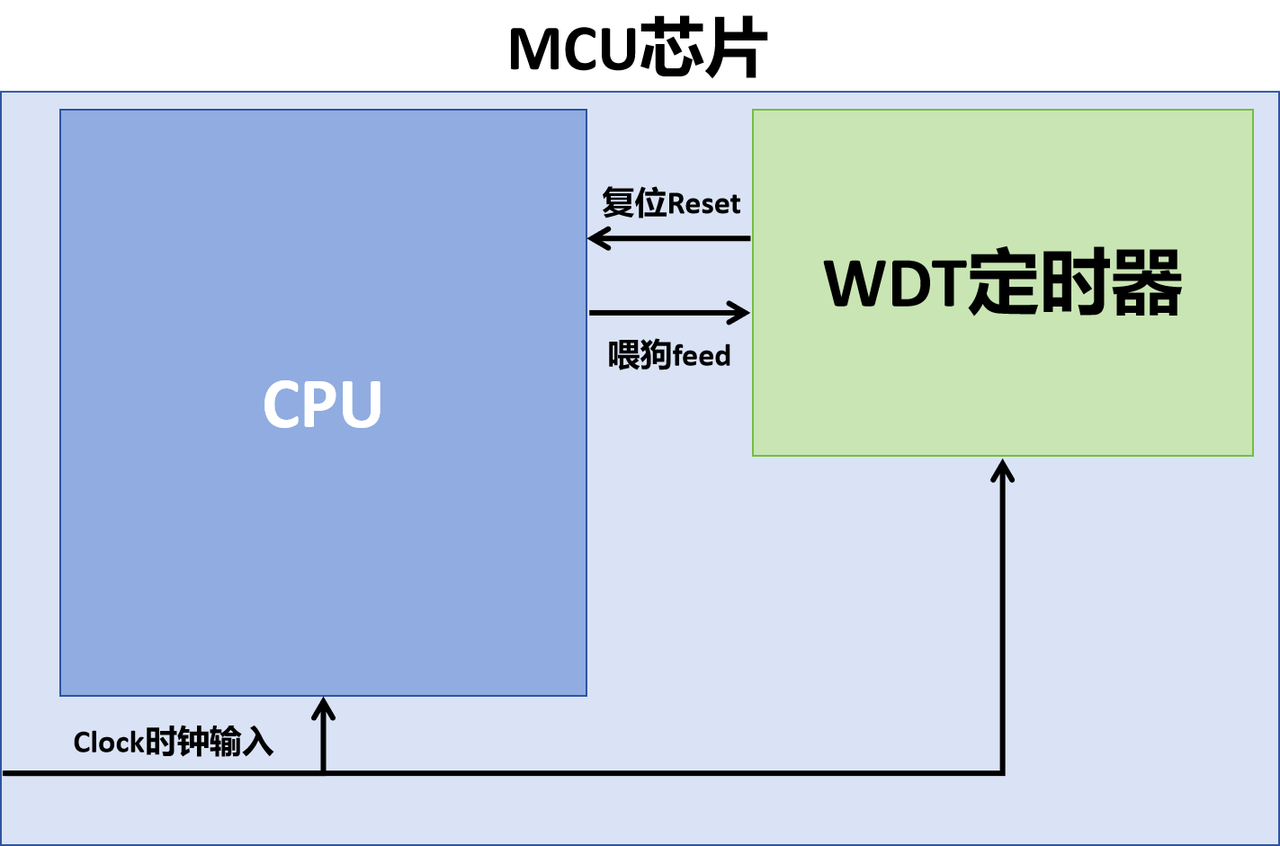
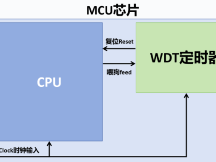
Watchdog reset commands have the highest interrupt priority within the program. This means no matter what task the system is executing, a watchdog reset signal can preempt the current task and perform a system reset.
Its basic working principle:
- Start the watchdog timer At its core, the watchdog is a down‑counter timer configured to reset the microcontroller after a predefined interval. Once enabled, it begins counting down.
- Periodic reset Well‑behaved application software must reset the watchdog before its countdown expires. This operation is commonly called “feeding the dog” or “kicking the dog”. This is usually achieved by calling the watchdog‑reset function inside the main loop or in a timer callback.
- System reset If the watchdog countdown completes without being reset, a system reset (reboot) is triggered, helping the system recover from abnormal conditions.
Based on working principle, watchdogs are divided into the Independent Watchdog (IWDG) and the Window Watchdog (WWDG):
Independent Watchdog (IWDG) The IWDG runs completely independent of the main microcontroller core. It is typically clocked by a separate low‑power oscillator such as a 32 kHz crystal or internal RC oscillator. Therefore it keeps working even when the main CPU or main system clock fails. The IWDG logic is simple and robust; a counter reaching zero generates a reset. After being started, the IWDG generally cannot be stopped or disabled via software. It is mainly used to recover from runaway code and infinite‑loop failures.
(Sample image missing)
Window Watchdog (WWDG) The key feature of WWDG is a valid time window. The watchdog reset‑kick must happen inside this specific time window. Resetting too early or too late will trigger a system reset. This mechanism effectively prevents infinite loops as well as premature or delayed watchdog‑feeding. The WWDG normally relies on the main system clock or other high‑frequency clock sources, so it may malfunction if the main clock fails. It is used to detect unexpected program‑flow deviations, such as code finishing far ahead of schedule or timing‑out beyond acceptable limits.
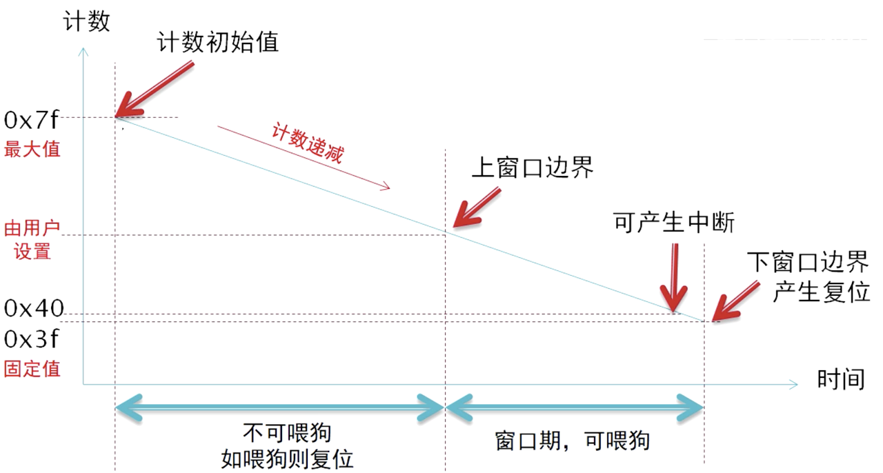
On STM32 microcontrollers, the window watchdog has an upper‑limit and a lower‑limit threshold. Feeding the watchdog within the range between user‑configured upper value and fixed lower limit 0x40 avoids reset. The WWDG uses a 7‑bit down‑counter with a maximum initial value of 0x7F. An early‑wake‑up interrupt can be enabled via configuration registers to generate an interrupt when the counter counts down to 0x40.
From a hardware‑structure perspective, watchdogs are classified as on‑chip watchdog peripherals and external watchdog chips:
On‑chip Watchdog Timer An on‑chip watchdog is built inside the microcontroller as a standard peripheral. It shares clock and resource domains with other peripherals such as timers and UART.
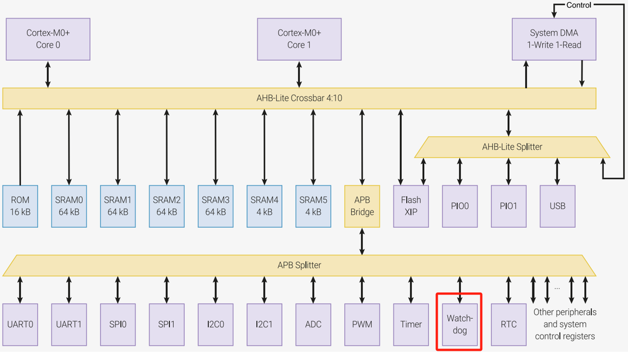
Raspberry Pi Pico on‑chip watchdog peripheral
Easy to use Being integrated inside the MCU, developers configure and control it directly through MCU registers, without extra external hardware or wiring.
High integration On‑chip watchdogs leverage internal MCU clock and power‑management units to achieve low‑power system supervision.
Vulnerable to MCU‑internal faults If the MCU main clock or other critical resources malfunction, the on‑chip watchdog may also be affected. For example, it may stop working when the main clock suffers unrecoverable failure.
External Watchdog Timer An external watchdog chip is a standalone integrated‑circuit connected to the MCU via GPIO or other interfaces. It can keep operating and supervise faults even during severe MCU malfunctions.
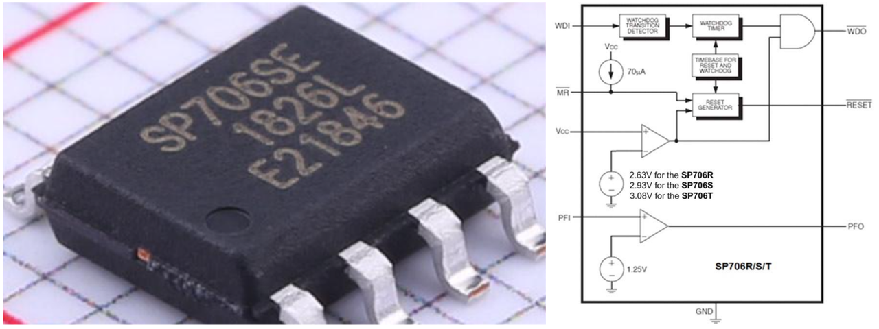
SP706 external watchdog chip, integrating watchdog timer and power‑supply monitoring functions
High reliability Because external watchdog chips run independently, they can still monitor and assert reset when the MCU fails. This independence makes them essential for high‑reliability applications.
High flexibility External watchdog chips usually offer richer configuration options: fine‑grained timing control, programmable timeout windows, and multiple reset‑output choices such as hard‑reset or soft‑reset signals.
Increased complexity and cost External watchdog chips demand additional hardware circuits and wiring, raising system complexity and bill‑of‑material cost. This can be a limiting factor for cost‑sensitive projects.
By implementation method, watchdogs are grouped into software watchdogs and hardware watchdogs:
Software Watchdog A software watchdog is implemented purely in application or operating‑system code. It periodically checks system status and triggers responses such as reset or warning messages. Developers reset a software timer in code to prevent timeout. When timeout occurs, the system may perform a software reset or invoke fault‑handling routines.
Dependent on main processor Since it is software‑based, it relies on correct execution of the main CPU and operating‑system. Severe failures in clocks or memory management may render the software watchdog ineffective.
High flexibility Software watchdogs are highly configurable. Developers can adjust timeout durations, alert behaviours, and implement different response logics for various conditions.
Resource overhead and complexity Software watchdogs consume CPU processing time. In high‑real‑time systems this may degrade application performance. In addition, implementing complete software‑watchdog logic increases code complexity.
Hardware Watchdog A hardware watchdog is realized by dedicated hardware circuitry. It exists either as an on‑chip MCU peripheral or as a separate external chip. It features a physical down‑counter that must be reset within the configured timeout period; otherwise it triggers system reset or other predefined actions.
Independence and reliability Hardware watchdogs are not dependent on application‑code execution. They are usually driven by separate clock sources, so they stay functional even when major system components malfunction. This makes them very suitable for mission‑critical systems.
Low resource overhead Hardware watchdogs consume almost no CPU resources. The application only needs to send periodic reset pulses, with minimal runtime performance impact.
Often non‑disabling after activation Many hardware watchdogs cannot be turned off by software once started. This guarantees continuous supervision, an important property for mission‑critical equipment.
For practical project development, it is recommended to use the built‑in on‑chip watchdog peripheral together with an additional external watchdog chip. When the MCU itself suffers hardware faults such as power‑supply fluctuations, clock failure or memory corruption, the internal WDT may also be impaired and fail to perform a reset. An external WDT runs completely independently of MCU internal resources.
In short, an external WDT provides an extra safety layer, improving system redundancy and reliability to avoid single‑point‑of‑failure total system crash. It guarantees that under worst‑case conditions the system can still reset safely and resume operation.