



Understanding Raspberry Pi Pico USB: Hardware, Architecture & MicroPython Control
RP2040 USB works in host/device modes. Pico MicroPython uses built‑in USB‑CDC for data transfer.
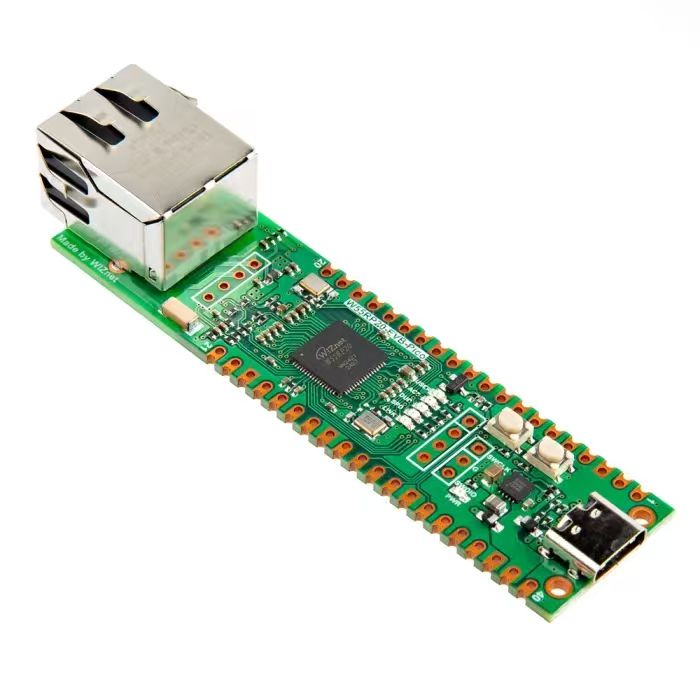
1.Overview of Raspberry Pi Pico USB Peripherals
The RP2040 chip on Raspberry Pi Pico integrates a USB 2.0 controller that can operate in the following modes:
A full‑speed device (12 Mbps)
A host communicating with low‑speed (1.5 Mbps) and full‑speed devices, including multiple downstream devices connected via a USB hub
RP2040 has a built‑in USB 1.1 PHY chip. The USB controller connects to the chip’s DP(D+) and DM(D‑) pins through this PHY. The USB‑controller hardware implements the USB physical layer, data‑link layer and partial transaction‑layer functions. Programmers do not need to handle complex low‑level USB protocol details manually. Instead, developers focus on these tasks:
Configure controller parameters such as device address and endpoints
Supply data buffers for controller transmit and receive operations
Respond to controller interrupt events like transfer completion and endpoint status changes
The USB controller features 4 kB DPSRAM for storing USB‑device configuration and data buffers.
The USB controller supports two operating modes:
Device Mode:
USB 2.0‑compliant full‑speed device (12 Mbps)
Supports up to 32 endpoints (0 → 15 for both IN and OUT directions)
Supports control, isochronous, bulk and interrupt endpoint types with double‑buffering
3840‑byte usable buffer space inside DPSRAM, equivalent to 60 × 64‑byte buffers
Host Mode:
Communicates with full‑speed (12 Mbps) and low‑speed (1.5 Mbps) devices
Works with multiple devices over a USB hub, including low‑speed devices behind a full‑speed hub
Hardware can poll up to 15 interrupt endpoints
Interrupt endpoints notify hosts of hub connect/disconnect events, mouse movement and other signals
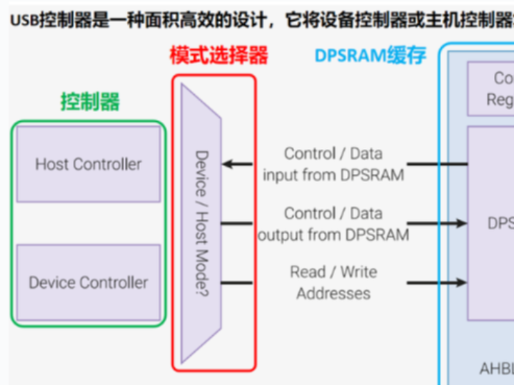
Structure of the USB peripheral: 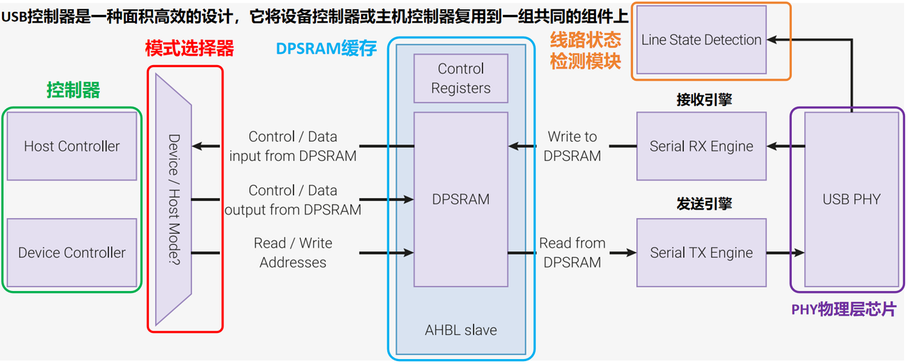
The USB peripheral consists mainly of the components listed below:
Integrated USB PHY Chip
Implements USB physical‑layer protocols including electrical characteristics, signal encoding and differential transmission
Provides electrical interface between USB DP/DM pins and controller digital logic
Drives DP and DM pins for transmission and performs differential reception for incoming data
Feeds single‑ended and differential received data to the line‑state‑detection module
USB Controller
Implements USB device‑side protocol stack and endpoint management
Manages data reception and transmission, plus generation and parsing of control signals
Buffer Memory
DPSRAM holds control registers and data buffers
The USB controller includes 4 kB (4096‑byte) dual‑port SRAM (DPSRAM)
DPSRAM can be accessed as 32‑bit memory at USB‑controller address 0 (0x50100000)
Supports 8‑bit / 16‑bit / 32‑bit access; set‑and‑clear alias operations are unsupported
Typical buffer length is 64 bytes:
Max buffer size for isochronous transfers: 1023 bytes
Max buffer size for other transfer types: 64 bytes
DPSRAM of USB controller must be treated as asynchronous and non‑atomic:
As dual‑port SRAM, it has one port for the processor and one port for the USB controller. Both may access the same memory address simultaneously. One may write while the other reads. Reading by the controller during CPU writes yields inconsistent data. This race condition must be avoided.
Line‑State‑Detection Module
Defines and detects bus states: bus reset, connect, suspend, resume, DATA1, DATA0 and more
Contains state machines for state detection and sends event signals to other hardware blocks USB has no shared clock; received RX data is sampled via internal clock
Full‑speed USB runs at 12 Mbps. RX data is sampled at 48 MHz, providing four clock cycles to capture and filter bus states. Filtered RX data is forwarded to the serial RX engine.
Receive Engine
The serial receive engine decodes data captured by the line‑state‑detection module. It extracts:
PID (Packet Identifier) of incoming packets
Device address of incoming traffic
Endpoint number of incoming traffic
Payload data bytes
It runs CRC checks on incoming data to detect receive errors. Errors trigger notifications to other hardware blocks and may raise interrupts.
Hardware generates errors if USB cable is disconnected mid‑transfer under host or device mode.
Transmit Engine
The serial transmit engine is the counterpart of the receive engine.It connects to the active controller (device or host). It builds TOKEN and DATA packets, calculates CRC values and transmits packets onto the USB bus.
2. Software Control Methods
Within MicroPython, USB devices fall into two categories:
1."Runtime" USB Devices:
1. Defined after MicroPython boots via Python APIs (USBDevice class)
2.Require runtime configuration and activation
2. "Built‑in" USB Devices:
1. Compiled into MicroPython firmware and always available
2.Usually includes USB‑CDC (virtual serial port) and optional USB‑MSC (mass‑storage class) 3. Ready‑to‑use without extra configuration
MicroPython provides the low‑level Python API USBDevice class for implementing USB‑device drivers:
Constructor:
USBDevice is a singleton class; every constructor call returns the identical object reference.
Main Methods:
config() — configures USB‑device descriptors and callback functions
active() — enables or disables runtime USB devices
builtin_driver attribute — reads or modifies built‑in USB‑driver settings
remote_wakeup() — wakes a suspended USB host
submit_xfer() — submits non‑control transfers
stall() — sets or queries endpoint STALL status
Constants:
BUILTIN_NONE, BUILTIN_DEFAULT, BUILTIN_CDC, BUILTIN_MSC, BUILTIN_CDC_MSC represent different built‑in USB‑driver configurations.
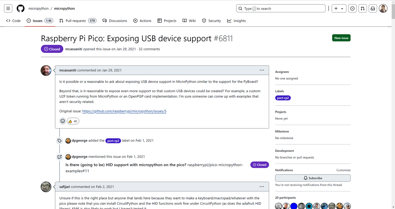
Unfortunately, as shown in replies from the link below, Raspberry Pi Pico cannot use the USBDevice class to control runtime USB devices like STM32‑based PyBoard: https://github.com/micropython/micropython/issues/6811
Referring to previous REPL interpreter documentation: default MicroPython firmware for Raspberry Pi Pico carries a built‑in USB‑CDC driver offering a virtual serial channel. This USB‑CDC is a firmware‑integrated "Built‑in" device usable with zero extra configuration. We can leverage this virtual serial port together with system standard input and output to complete USB data transmission.