



Understand OSI Model: Principles, Encapsulation & TCP/IP Full Guide
It explains OSI seven‑layer principles, encapsulation and TCP/IP basics.
1.OSI Open Systems Interconnection Model
Before explaining ETH Ethernet communication, we need to understand the OSI Open Systems Interconnection Model. The OSI model is a conceptual model for network communication developed by the International Organization for Standardization (ISO) in the 1980s. The OSI model divides the network‑communication process into seven layers, ranging from the Physical Layer (Layer 1) up to the Application Layer (Layer 7). Each layer has specific functions and responsibilities to guarantee accurate data transmission across different computer systems.
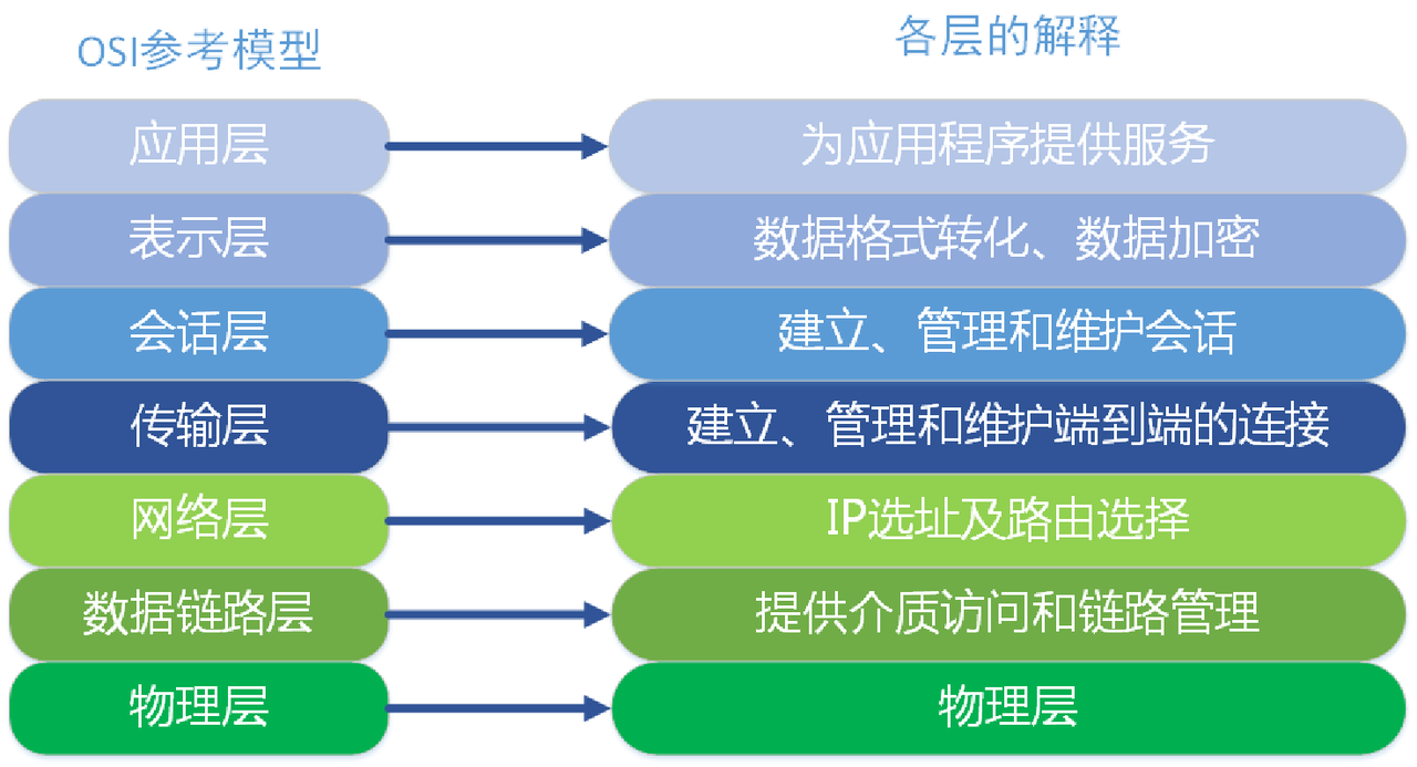
The OSI model contains seven layers, listed from top to bottom:
Application Layer Application Layer is the uppermost layer of the OSI model and provides services directly to end users. Application‑layer protocols define communication rules for applications, such as HTTP, FTP, SMTP, DNS.
Presentation Layer Presentation Layer handles data formatting and encryption. It defines data encoding, compression, encryption and decryption mechanisms.
Session Layer Session Layer establishes, manages and terminates sessions between applications. It offers session setup, data exchange and session‑recovery capabilities.
Transport Layer Transport Layer manages end‑to‑end communication, performing data segmentation, reassembly, flow control and error detection. Common transport‑layer protocols include TCP (Transmission Control Protocol) and UDP (User Datagram Protocol).
Network Layer Network Layer performs packet routing and forwarding to deliver packets across disparate networks to their destinations. It defines IP addresses and routing protocols. Typical network‑layer protocols include IP (IPv4 and IPv6), ICMP, IGMP.
Data Link Layer Data Link Layer establishes and manages data links between adjacent network nodes. It implements frame encapsulation‑decapsulation, error detection and flow‑control functions.
Physical Layer Physical Layer transmits bit‑streams (electrical signals of 0 and 1) over physical media. It defines electrical specifications, interface standards and cable types. Representative physical‑layer protocols and devices include Ethernet, USB, Bluetooth and hubs.
Diagram of data formats for each OSI layer: from Physical Layer to Application Layer. Every layer has dedicated data formats and processing workflows. The Physical Layer processes raw bit‑streams as continuous sequences of 0 and 1. The Data Link Layer encapsulates bits into Frames with header control information including source and destination addresses. Network‑layer data units are Packets containing source‑IP, destination‑IP and routing information. Transport‑layer units are Segments or Datagrams corresponding to TCP and UDP for reliable end‑to‑end delivery. Session Layer builds, manages and tears down sessions. Presentation Layer takes care of data representation, encryption and compression. Application Layer interacts directly with users; its data formats depend on application requirements such as HTTP requests‑responses or email content.
Diagram for OSI‑layer functions and supported protocols: each layer has distinct responsibilities and compatible protocols. Physical Layer handles physical bit transmission; supported protocols are Ethernet, Token Ring, FDDI. Data Link Layer generates, receives and detects errors for frames; supported protocols include Ethernet, Token Ring, PPP. Network Layer routes and forwards packets; supported protocols include IP, ICMP, ARP. Transport Layer delivers reliable end‑to‑end transmission; supported protocols include TCP and UDP. Session Layer creates, maintains and closes sessions; supported protocols include NetBIOS, SQL. Presentation Layer processes representation, encryption and compression; supported protocols include SSL, TLS. Application Layer serves users directly; supported protocols include HTTP, FTP, SMTP.
Relationship between Ethernet and the OSI model:
Physical Layer Ethernet’s Physical Layer maps to OSI Layer 1, responsible for bit‑stream transmission over physical media including fiber‑optic cables, twisted‑pair wires and related interface standards.
Data Link Layer Ethernet’s Data Link Layer corresponds to OSI Layer 2. It establishes and manages node‑to‑node data links and defines frame formats plus error‑detection‑correction mechanisms.
Network Layer Ethernet itself contains no native Network Layer. Nevertheless, Ethernet packets travel through Network‑layer protocols such as IP, corresponding to OSI Layer 3.
In short, Ethernet is a practical OSI‑model implementation for local‑area networks delivering Physical‑Layer and Data‑Link‑Layer specifications. The OSI model supplies a more general framework for understanding and designing diverse network protocols.
Engineers leverage the OSI model to organize and model complex network architectures. Functional operations of system components can be separated by their primary working layers. Abstraction breaks systems into smaller, manageable parts for easier holistic comprehension. The OSI model does not dictate exact protocols for layer‑to‑layer communication; it defines required protocol tasks. This model standardizes network‑system development, enabling people to understand, build and disassemble highly‑complex systems without prior deep knowledge. Detailed internal information is abstracted away so engineers do not need full awareness of every implementation detail. Within modern applications, lower‑level networks and protocols can be abstracted to simplify design and development work.
Basic prerequisites for learning the OSI model
Before studying the OSI model you should master common networking terms: node, link, protocol, network, topology.
1.1 node
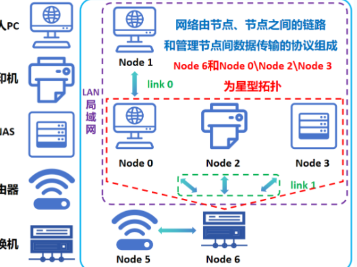
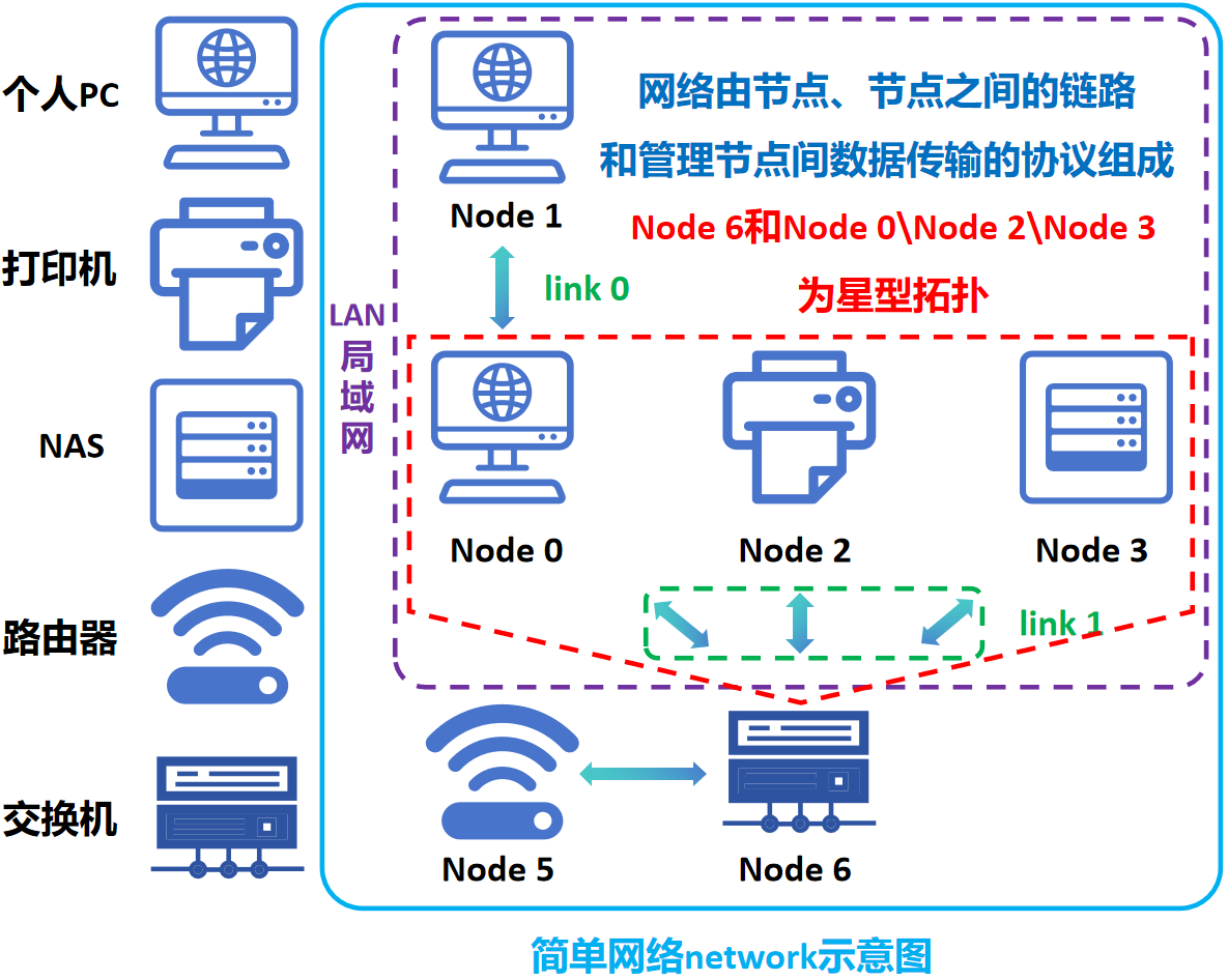
In computer networks, a node means any device connected to the network capable of sending and receiving data communications, for example computers, routers, switches. Nodes are fundamental building blocks of networks used to transmit, receive and forward data. Nodes can connect directly: node 0 connects straight to node 1. Intermediate nodes may sit between endpoints: a switch or router can sit between node 0 and node 2.
1.2 link
A link represents physical wiring or logical paths connecting network nodes. Links can be physical communication lines or virtual logical channels. Links can be wired (for instance Ethernet cables) or wireless (for example Wi‑Fi). Links support one‑to‑one or one‑to‑many topologies: link 0 is one‑to‑one, link 1 is one‑to‑many.
1.3 protocol
“A protocol defines rules governing syntax (what can be communicated), semantics (how communication occurs), and synchronization (when and at what speed communication happens). Protocols may be implemented in hardware, software, or a combination of both. Anyone can create protocols, yet widely‑adopted protocols follow formal standards.”
— Walter Goralski, Illustrated Network: How TCP/IP Works in Modern Networks
Simply put, protocols are sets of rules and standards for network communication specifying data format, sequence and error‑handling mechanisms.
1.4 network
A network is a complex system built from nodes and links enabling data exchange between nodes. Common network types include LAN, HAN, CAN, MAN, WAN, BAN, VPN.
Local‑Area Network LAN Limited geographic coverage, normally within a building or campus; high transmission speed and low cost.
Wide‑Area Network WAN Extensive geographic coverage crossing countries or continents; relatively low speed and higher cost.
Metropolitan‑Area Network MAN Scope sits between LAN and WAN, typically covering one city and its surrounding districts.
Personal‑Area Network PAN Person‑centered networks using wireless technologies such as Bluetooth, ZigBee.
Broadcast‑Area Network BAN Point‑to‑multipoint networks supporting broadcast information delivery.
Virtual Private Network VPN Builds private secure communication tunnels over public internet infrastructure.
Controller‑Area Network CAN Network standard dedicated to electronic‑system communication inside automobiles.
Industrial‑control‑system Network MAN Networks for industrial‑automation and control‑system communication.
1.5 topology
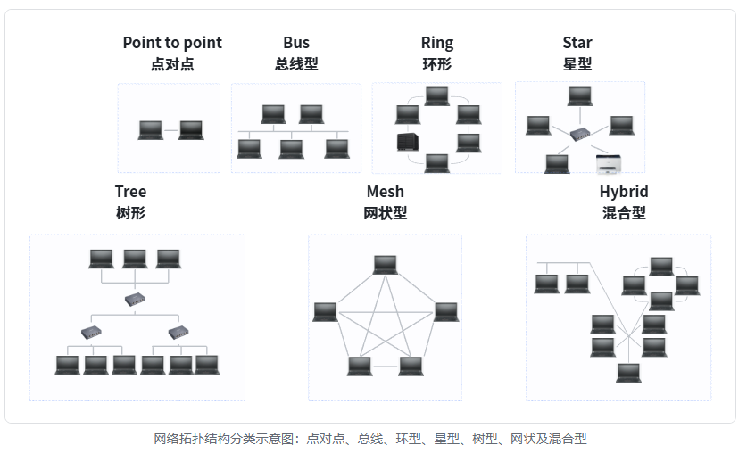
Topology describes physical or logical arrangement of network nodes and links, influencing network performance and reliability. Well‑known topologies include star, ring, bus, tree and mesh.
2.OSI Physical Layer
2.1 Core functions of Physical Layer
OSI Physical Layer is Layer 1 of the seven‑layer stack, defining physical and electrical characteristics for network communication. Key components are listed below.
Nodes and network hardware Nodes denote devices sending, receiving or repeating data. Common network‑hardware examples:
Hub Basic network device aggregating multiple Ethernet devices into one logical network segment.
Repeater Extends network reach by regenerating and amplifying signals to mitigate signal attenuation.
Router Connects different network segments and selects optimal forwarding paths for packets.
Computers, printers End‑terminal devices generating, receiving and processing data traffic.
Hardware components Antennas for wireless links, signal amplifiers, Network Interface Cards NIC providing network connectors.
Device‑interface mechanisms dealing with physical connections and connector standards
Cable connections Cables plug into device sockets via physical connectors such as RJ45 Ethernet jacks.
Connector specifications RJ45 connectors feature 8 pins with dedicated transmit‑receive assignments.
Pin states Pin activity is governed by electrical high‑level and low‑level signals.
Functional and program logic covering pin assignments and inter‑device communication logic
Pin functions Certain Ethernet pins serve for TX transmission; others serve for RX reception.
Program logic Event‑sequence logic ensuring correct Layer‑2 Data‑Link‑Layer communication between nodes.
Cable protocols and specifications defining technical communication details
Ethernet CAT series Standards for Ethernet cables and physical connectors.
USB Standard for connecting computers to peripheral hardware.
DSL Digital‑Subscriber‑Line Technology transmitting digital data across telephone lines.
Cable types for different network‑environment requirements
Shielded‑Twisted‑Pair STP Reduces electromagnetic interference.
Unshielded‑Twisted‑Pair UTP Widely deployed for Ethernet wiring.
Coaxial cable Used for television and broadband‑internet connections.
Signal types for data transmission
Baseband signal Transmits one bit‑stream at a time, typical for Ethernet.
Broadband signal Conveys multiple bit‑streams simultaneously, common for broadband‑internet services.
Signal‑transmission approaches: wired or wireless
Wired transmission Electrical signals over Ethernet cables; optical signals over fiber‑optic media.
Wireless transmission Radio‑wave‑based Wi‑Fi operating at 2.4 GHz or 5 GHz frequency bands.
Network standards Examples like 100BASE‑T defining Ethernet bit‑rate and physical‑media requirements.
2.2 Basic data units: bit and byte
For Physical‑Layer communication you must understand bit‑byte concepts, bit synchronization and transmission modes.
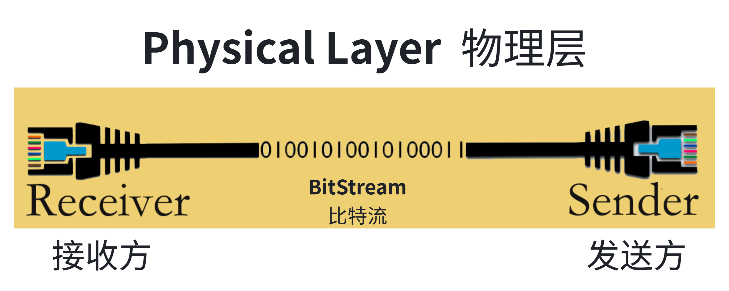
Physical‑layer communication fundamentals: bit‑byte transmission principles and synchronization mechanisms
Physical‑layer data units: bit and byte
bit Smallest transmission unit with only two states: 0 and 1. All higher‑level units such as byte, frame and packet are assembled from bits.
byte Composed of 8 bits; fundamental processing unit inside computers. One byte can represent 256 distinct numerical values (2^8).
Bit transmission and synchronization
Data‑transfer rate Measured in bits‑per‑second bps; units include Mbps megabits‑per‑second and Gbps gigabits‑per‑second.
Bit synchronization Sender and receiver must align timing references for correct bit reception. Synchronization is achieved via separate clock signals or timing information embedded inside data streams.
Transmission methods
Signal‑delivery approaches Wired: electrical Ethernet signals, optical fiber‑optic signals. Wireless: radio‑wave‑based Wi‑Fi, Bluetooth.
Modulation techniques Wireless communication relies on modulation schemes such as AM, FM, QAM.
Transmission modes
Simplex mode Data flows in one single direction only: one node transmits, another only receives. Example: broadcast television signals.
Half‑Duplex mode Bidirectional communication, yet transmission directions cannot happen simultaneously; send‑receive operations alternate. Example: walkie‑talkie radio devices.
Full‑Duplex mode Simultaneous two‑way data transfer. Examples: modern telephone calls, full‑duplex Ethernet.
3.OSI Data Link Layer
3.1 Core functions of Data Link Layer
OSI Data Link Layer is Layer 2 delivering reliable data delivery between directly‑attached network nodes. It organizes incoming Physical‑Layer bit‑streams into frames and executes error‑detection‑correction to guarantee transmission reliability. Main functions:
Data encapsulation Encapsulate Network‑Layer packets inside frames adding header‑footer control fields including addresses and error‑check codes. Each frame consists of frame header, payload data field and frame trailer.
Physical‑address addressing Use MAC Media‑Access‑Control addresses to uniquely identify every network‑attached device. Frame send‑receive operations are performed based on MAC addresses.
Frame synchronization Correctly detect frame boundaries through dedicated start‑of‑frame and end‑of‑frame marker sequences.
Error detection and correction Deploy CRC Cyclic‑Redundancy‑Check or comparable error‑check codes for transmission‑fault detection. Request retransmissions to recover corrupted data frames after error discovery.
Flow control Adjust transmit‑receive data speeds preventing receiver‑buffer overflow.
Link management Establish, maintain and tear down physical communication links. Workflows include link initialization, link maintenance and link release.
3.2 LLC sub‑layer and MAC sub‑layer
The Data Link Layer is subdivided into two sub‑layers.
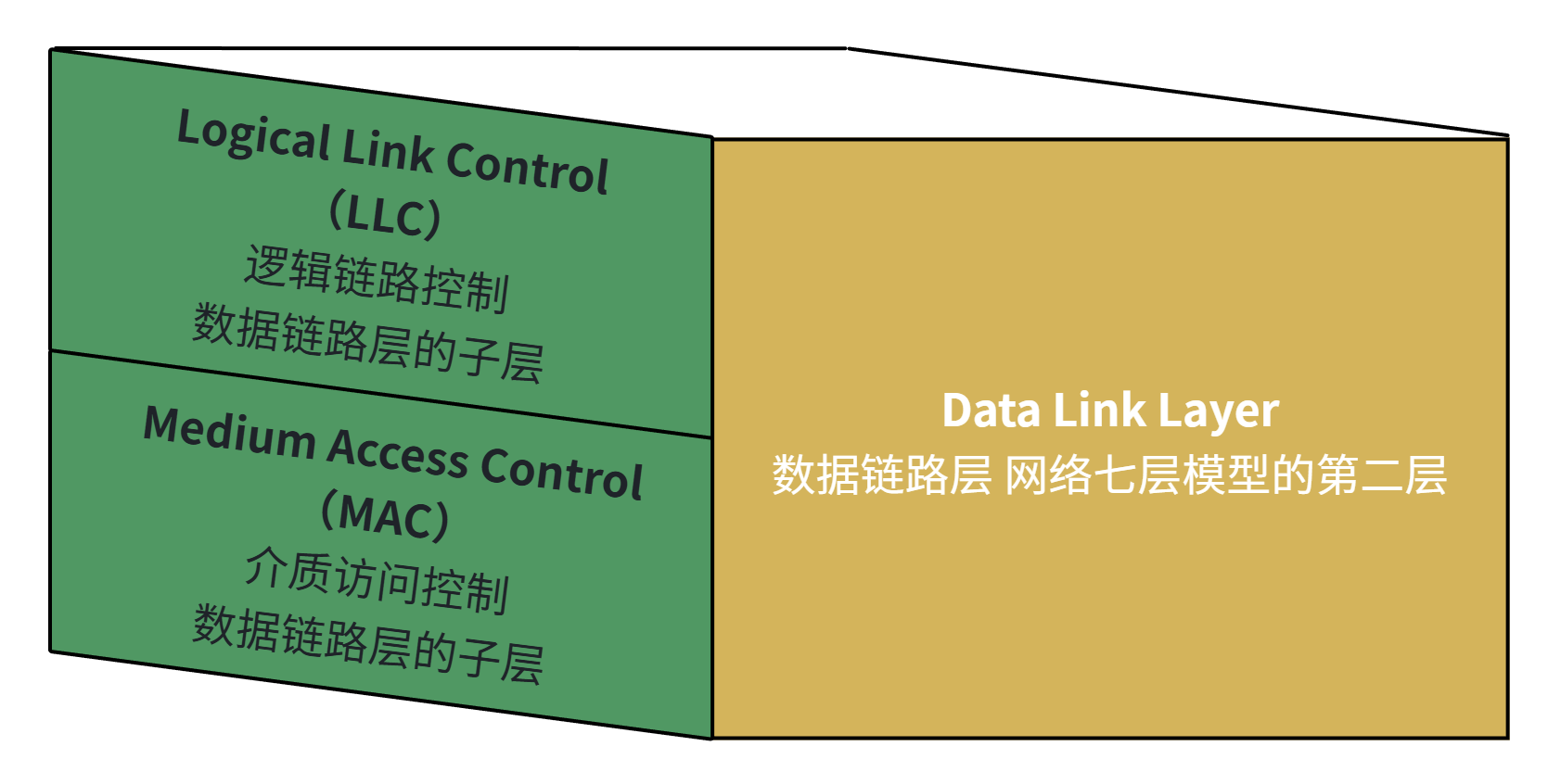
Data‑Link‑Layer sub‑layer division
LLC Logical‑Link‑Control sub‑layer Interfaces toward Network Layer, handling multiple upper‑layer network protocols. Implements flow‑control, error‑control and frame‑synchronization capabilities.
MAC Media‑Access‑Control sub‑layer Interfaces toward Physical Layer, regulating shared‑medium access. Realizes physical‑address addressing, frame delimitation and media‑access‑control logic. MAC sub‑layer assigns unique hardware identifiers known as MAC addresses for network‑device differentiation.
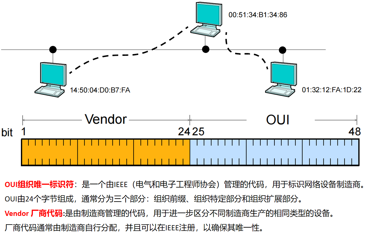
MAC addresses contain OUI Organizationally‑Unique‑Identifier and vendor‑manufacturer codes.
Switches operate on Data‑Link‑Layer Layer 2 by maintaining MAC‑address tables also known as CAM Content‑Addressable‑Memory tables tracking all connected‑device MAC addresses inside a LAN. Whenever a switch receives an incoming frame it records source‑MAC and ingress‑port information updating its MAC table. Frames get forwarded to correct egress ports according to destination‑MAC addresses enabling efficient intra‑LAN communication.
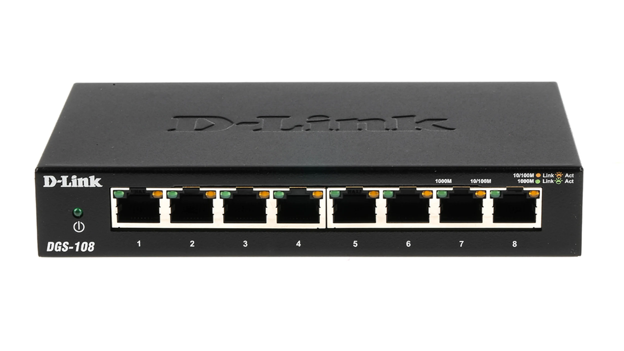
DGS‑108 8‑port Ethernet switch
4.OSI Network Layer
4.1 Core functions of Network Layer
OSI Network Layer is Layer 3 responsible for packet forwarding and route selection ensuring data travels from source node toward destination node. The Network Layer enables node‑to‑node communication and cross‑LAN data forwarding through routers. It solves challenges related to network topology, path‑selection and inter‑network connectivity. Main functions:
Path selection and routing Determine optimal forwarding paths for packets from source to destination nodes. Dynamically compute and maintain routing tables with routing protocols and algorithms such as OSPF, BGP.
Logical‑address assignment Identify network devices via IP addresses IPv4 or IPv6. IP addresses include network segment part and host identifier part defining device location inside networks.
Packet encapsulation‑decapsulation Encapsulate Transport‑Layer segments into complete packets adding Network‑Layer header fields. Receiving hosts decapsulate inbound packets and pass extracted segments upward to Transport Layer.
Packet fragmentation and reassembly Split large packets into smaller fragments respecting network MTU Maximum‑Transmission‑Unit limits. Receiving hosts reassemble fragments restoring original complete packets.
Error handling and diagnostics Detect and manage errors appearing during packet transit. Utilize protocols such as ICMP Internet‑Control‑Message‑Protocol for network‑error reporting and diagnostic feedback.
4.2 Routers and routing tables
Routers work at Network Layer forwarding packets between source and destination nodes, interconnecting distinct networks and governing cross‑network communication. Routers connect toward ISP Internet‑Service‑Provider networks delivering internet access, perform NAT Network‑Address‑Translation and enforce security functions to achieve efficient, reliable multi‑network data delivery.
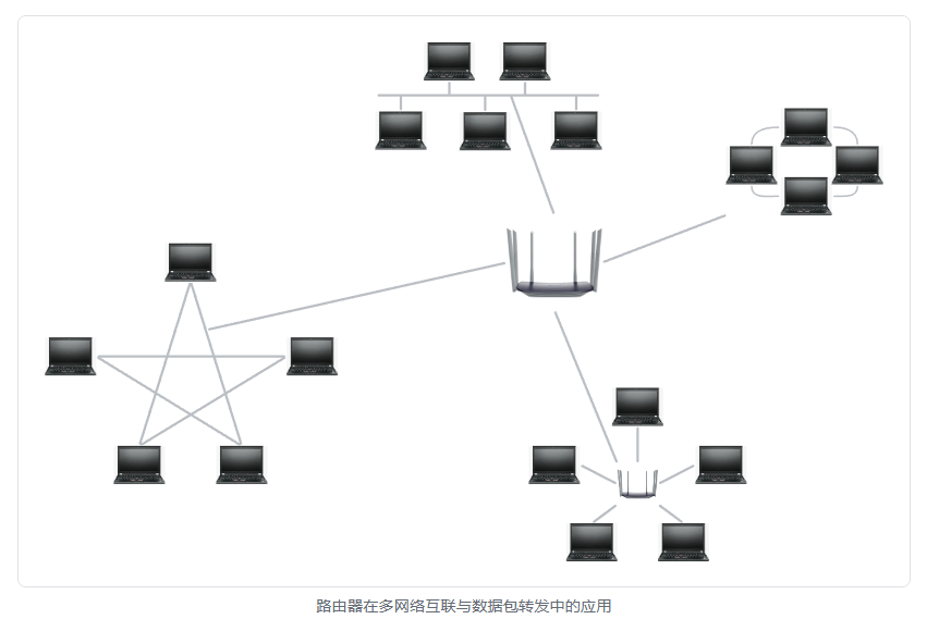
Routers for multi‑network interconnection and packet forwarding
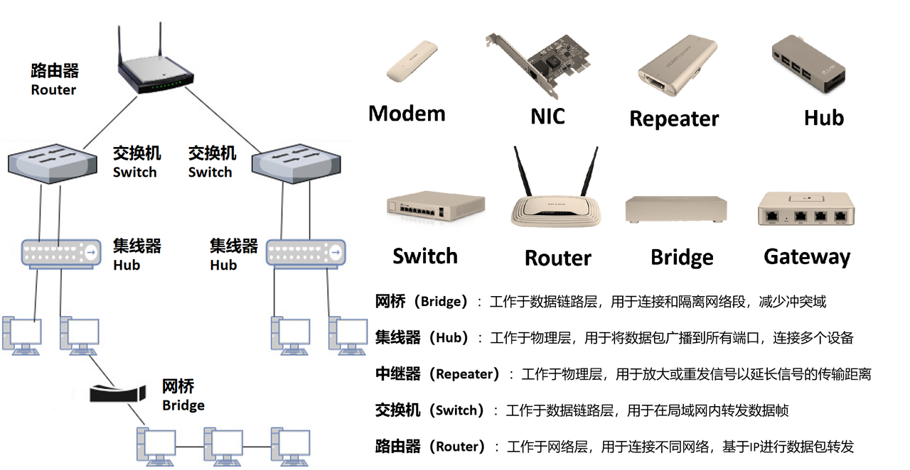
Important distinction: repeaters, hubs, bridges, switches and routers
Routers keep all addressing and routing information inside routing tables holding Network‑Layer metadata to decide packet‑forwarding pathways. Sample routing‑table entries demonstrate typical table fields and content.
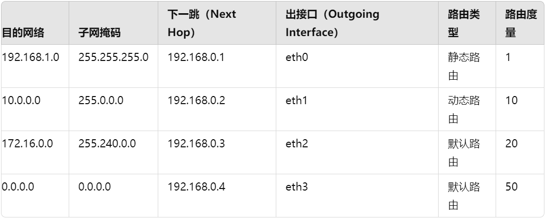
Routing‑table entry fields:
Destination Network Target network‑address for incoming packets.
Subnet Mask Defines target‑network range separating IP‑address network portion and host portion.
Next Hop IP address for downstream router or gateway toward destination networks.
Outgoing Interface Physical network‑interface used to transmit packets toward destination networks.
Route Type Marks route origin: static route, dynamically‑learned route, default route etc.
Metric Numerical priority value for path evaluation; smaller values represent higher‑priority routes.
Sample‑entry explanations: Traffic destined for network 192.168.1.0/24 forwards via next‑hop 192.168.0.1 out interface eth0. This entry is static‑configured with metric 1. Traffic destined for network 10.0.0.0/8 forwards via next‑hop 192.168.0.2 out interface eth1. This entry is dynamically‑learned with metric 10. Traffic destined for network 172.16.0.0/12 forwards via next‑hop 192.168.0.3 out interface eth2. This entry represents a default‑route candidate with metric 20. 0.0.0.0/0 denotes full default‑route matching all unmatched destination networks. Matching traffic forwards via next‑hop 192.168.0.4 out interface eth3 with metric 50; default‑route entries normally carry lowest forwarding priority.
Once nodes join the internet they obtain IP Internet‑Protocol addresses. Two major IP‑address versions are in common‑use today:
IPv4 Internet‑Protocol version 4 Widely‑deployed IP‑protocol variant with 32‑bit address space. Supports packet fragmentation, routing and cross‑network interconnection. IPv4 addresses consist of four decimal numeric groups each ranging from 0 to 255 separated by dots, for example 172.16.254.4.
IPv6 Internet‑Protocol version 6 Next‑generation IP protocol with 128‑bit address space solving IPv4‑address‑exhaustion issues. Offers enhanced extensibility, auto‑configuration and improved security features. IPv6 addresses use 8 groups of hexadecimal numbers separated by colons, for example 2001:0db8:85a3:0000:0000:8a2e:0370:7334.
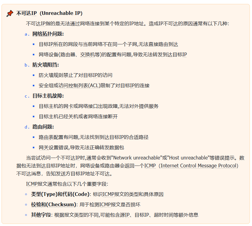
ARP Address‑Resolution‑Protocol translates Network‑Layer IP addresses into Data‑Link‑Layer MAC addresses. This translation process is essential for LAN‑internal device communication, because link‑layer frame transmission requires MAC‑address identifiers. ARP acts as bridging mechanism between Network Layer and Data Link Layer.
4.3 Typical gateway and subnet‑mask configuration
Configuring network devices including computers, routers or embedded‑system hardware normally requires setting IP‑address, subnet‑mask and gateway‑address parameters. Example configuration values: IP address: 192.168.1.100 Subnet mask: 255.255.255.0 Gateway address: 192.168.1.1
Gateway addresses represent router‑subnet egress points used when local devices need to communicate toward external remote networks. When local hosts generate packets for non‑local destinations they forward traffic to their assigned gateway, and gateways relay packets toward remote‑network gateways until reaching target hosts. This workflow describes cross‑subnet packet forwarding between Network A and Network B.
Take for instance Network A with IP‑address range 192.168.1.1‑192.168.1.254 and subnet‑mask 255.255.255.0; Network B with IP‑address range 192.168.2.1‑192.168.2.254 and subnet‑mask 255.255.255.0. Without routers deployed, TCP/IP communication cannot succeed between Network A and Network B even when both networks connect to one shared switch or hub. TCP/IP stack performs bitwise‑AND arithmetic combining host‑IP and subnet‑mask values and judges hosts reside inside different sub‑networks when computed network‑address results diverge. Gateway devices are mandatory to realize cross‑subnet communication.
Subnet masks split one complete IP‑address into network‑address portion and host‑address portion determining subnet boundaries for connected devices. Subnet masks never function independently and must always work paired with IP addresses. Devices perform bitwise‑AND operations between destination‑IP and local subnet‑mask deciding whether target hosts sit within the same local subnet or require gateway‑assisted forwarding.
Common subnet‑mask formats:
255.255.255.0 Normally applied for Class‑C networks delivering 256 total host addresses, with 254 usable host addresses after reserving network‑address and broadcast‑address entries.
255.255.0.0 Applied for Class‑B networks delivering 65536 total host addresses.
255.0.0.0 Applied for Class‑A networks delivering 16777216 total host addresses.
Bitwise‑AND calculation rules for IP‑address and subnet‑mask combinations: 0 AND any numeric value yields 0. 1 AND any numeric value yields the original numeric value itself.
4.4 Basic data unit: packet
Network‑Layer data units are known as packets built from Network‑Layer header and payload segments.
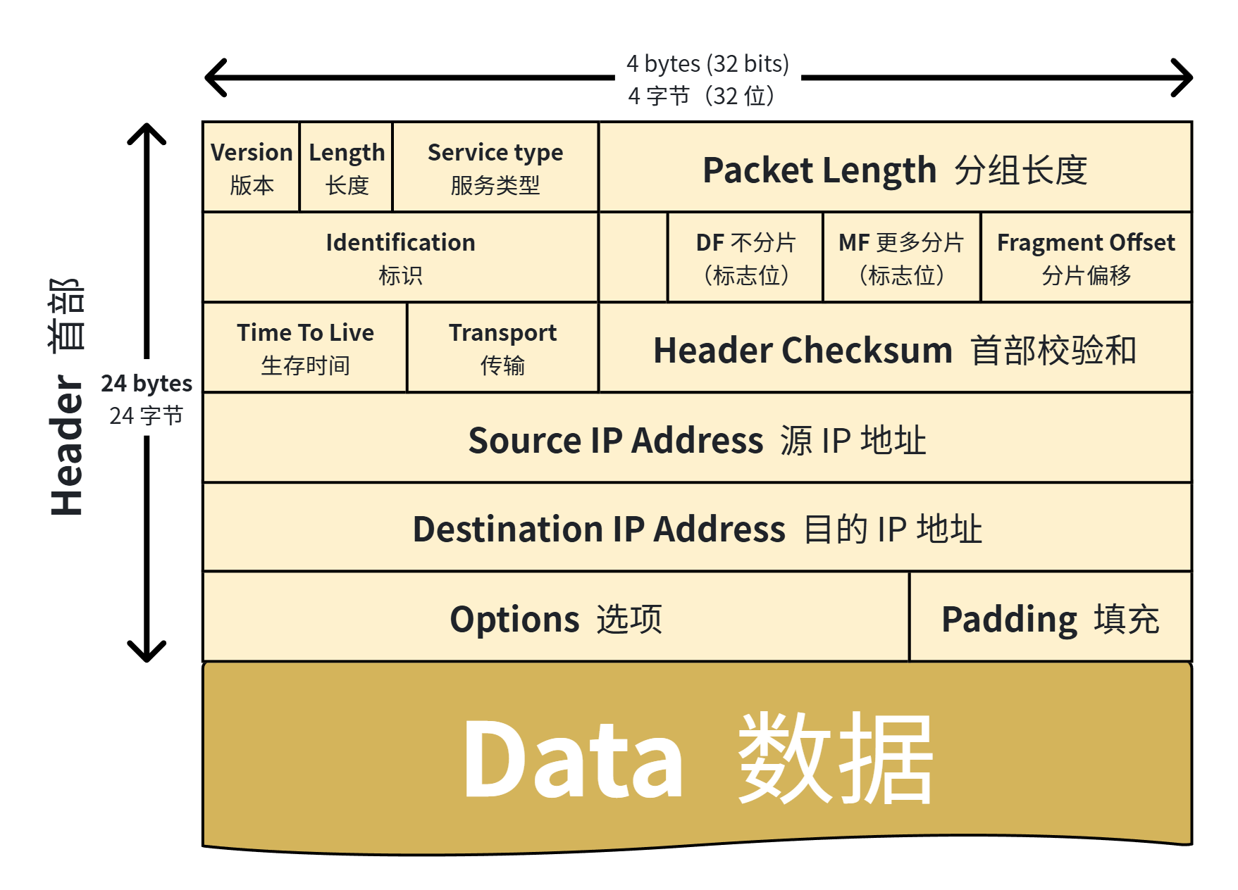
Network‑layer data unit: packet structure and IP‑header field analysis
Header Source‑IP address: IP identifier for sending node. Destination‑IP address: IP identifier for receiving node. Additional control metadata: protocol type, TTL Time‑To‑Live, identification, flags, fragment offset.
Payload Carries Transport‑Layer‑originated data segments.
Sample IPv4‑packet structural demonstration:
Header:
- Version: 4
- IHL: 5 (20 bytes)
- Type of Service: 0
- Total Length: 60 bytes (header 20 bytes + data 40 bytes)
- Identification: 12345
- Flags: 0x2 (Don't Fragment)
- Fragment Offset: 0
- TTL: 64
- Protocol: 6 (TCP)
- Header Checksum: 0x1a2b
- Source IP Address: 192.168.1.10
- Destination IP Address: 192.168.1.20
- Options: None
Payload (Data):
- Data: [TCP Segment]
  - Source Port: 12345
  - Destination Port: 80
  - Sequence Number: 123456789
  - Acknowledgment Number: 987654321
  - Data Offset: 5 (20 bytes)
  - Flags: 0x18 (PSH, ACK)
  - Window Size: 65535
  - Checksum: 0xabcdef
  - Urgent Pointer: 0
  - Data: "Hello, World!"
Header‑field explanations:
Version 4‑bit field marking IP‑protocol version; value 4 represents IPv4.
IHL Internet‑Header‑Length 4‑bit field measuring IP‑header length counted in 32‑bit words (4‑byte units).
Type of Service ToS 8‑bit field indicating packet priority and quality‑of‑service expectations.
Total Length 16‑bit field measuring full‑packet byte‑count including header and payload sections.
Identification 16‑bit unique‑packet identifier mainly used during packet‑fragmentation workflows.
Flags 3‑bit flags indicating fragmentation permission and existence of follow‑on fragments.
Fragment Offset 13‑bit offset marking position for each fragment inside original complete datagram.
TTL Time‑To‑Live 8‑bit hop‑count limit preventing infinite packet looping across networks.
Protocol 8‑bit field identifying upper‑layer payload‑protocol such as TCP or UDP.
Header Checksum 16‑bit checksum detecting bit‑errors within IP‑header content.
Source IP Address 32‑bit IPv4 source‑host identifier.
Destination IP Address 32‑bit IPv4 destination‑host identifier.
Options Optional variable‑length field carrying extended control metadata such as timestamps or record‑route instructions.
Padding Filler bytes ensuring total IP‑header length aligns to multiples of 32‑bit words.
Payload Data segments originating from Transport‑Layer protocols including TCP segments or UDP datagrams.
5.OSI Transport Layer
5.1 Core functions of Transport Layer
Transport Layer is OSI Layer 4 delivering end‑to‑end data‑transmission services between source and destination endpoints. It prioritizes correct‑ordered packet arrival with minimal loss or corruption plus recovery workflows when required. Key responsibilities cover data segmentation‑reassembly, transmission control, flow‑control and error‑control mechanisms. Major functions:
Data segmentation and reassembly Split Session‑Layer data payloads into smaller segments on transmit side; receiving hosts reassemble segments restoring original complete data streams.
Transmission control Govern end‑to‑end communication ensuring reliable, accurate data delivery from source nodes toward destination nodes.
Error detection and correction Detect transmission‑induced corruption with checksum algorithms and trigger corrective retransmission operations.
Flow control Regulate transmit‑side data throughput avoiding receiver‑buffer overflow situations.
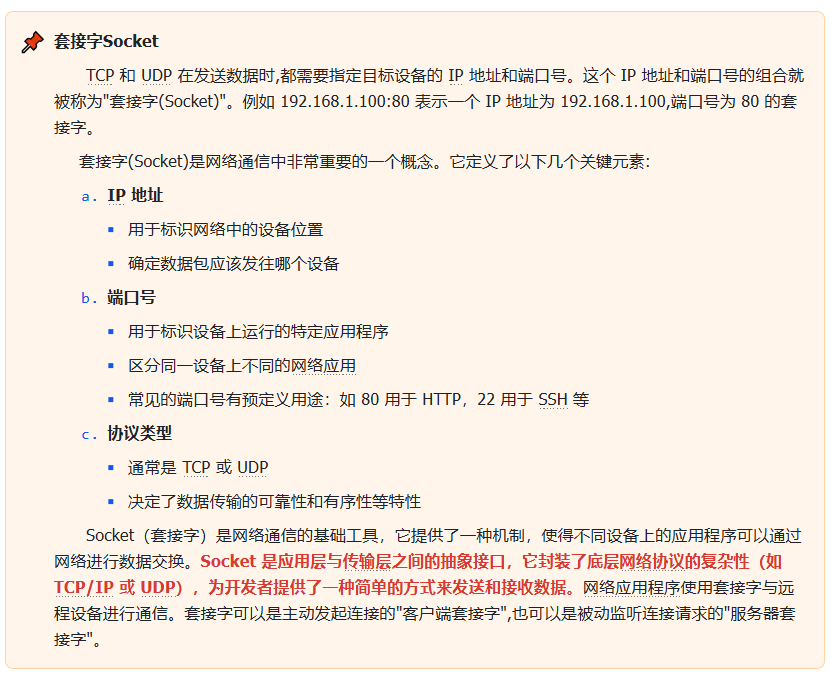
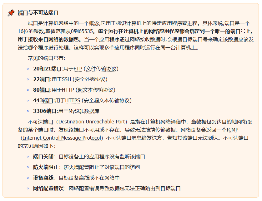
Port management Differentiate concurrent application‑level communication flows on single hosts by utilizing port‑number identifiers.
5.2 TCP protocol and UDP protocol
Two dominant Transport‑Layer protocols exist: TCP Transmission‑Control‑Protocol and UDP User‑Datagram‑Protocol.
TCP Transmission‑Control‑Protocol
Connection‑oriented Establishes logical connections before transmitting application data via Three‑Way‑Handshake workflow.
Reliable delivery Guarantees complete data delivery through ACK acknowledgment and packet‑retransmission mechanisms preserving data integrity and ordering.
Flow control Implements sliding‑window flow‑control preventing transmit‑side overload of receiving endpoints.
Error detection and correction Employs checksum validation and retransmission workflows repairing corrupted or lost segments.
Typical use‑cases Applications demanding reliable delivery: HTTP/HTTPS, FTP, SMTP.
UDP User‑Datagram‑Protocol
Connectionless No pre‑established logical connections. Individual datagrams transmit independently achieving low‑latency performance without reliability assurances.
Lightweight and efficient Omits acknowledgment and retransmission overhead; ideal for latency‑sensitive real‑time workloads.
Typical use‑cases DNS lookups, video streaming, online‑gaming workloads where strict reliability is non‑mandatory.
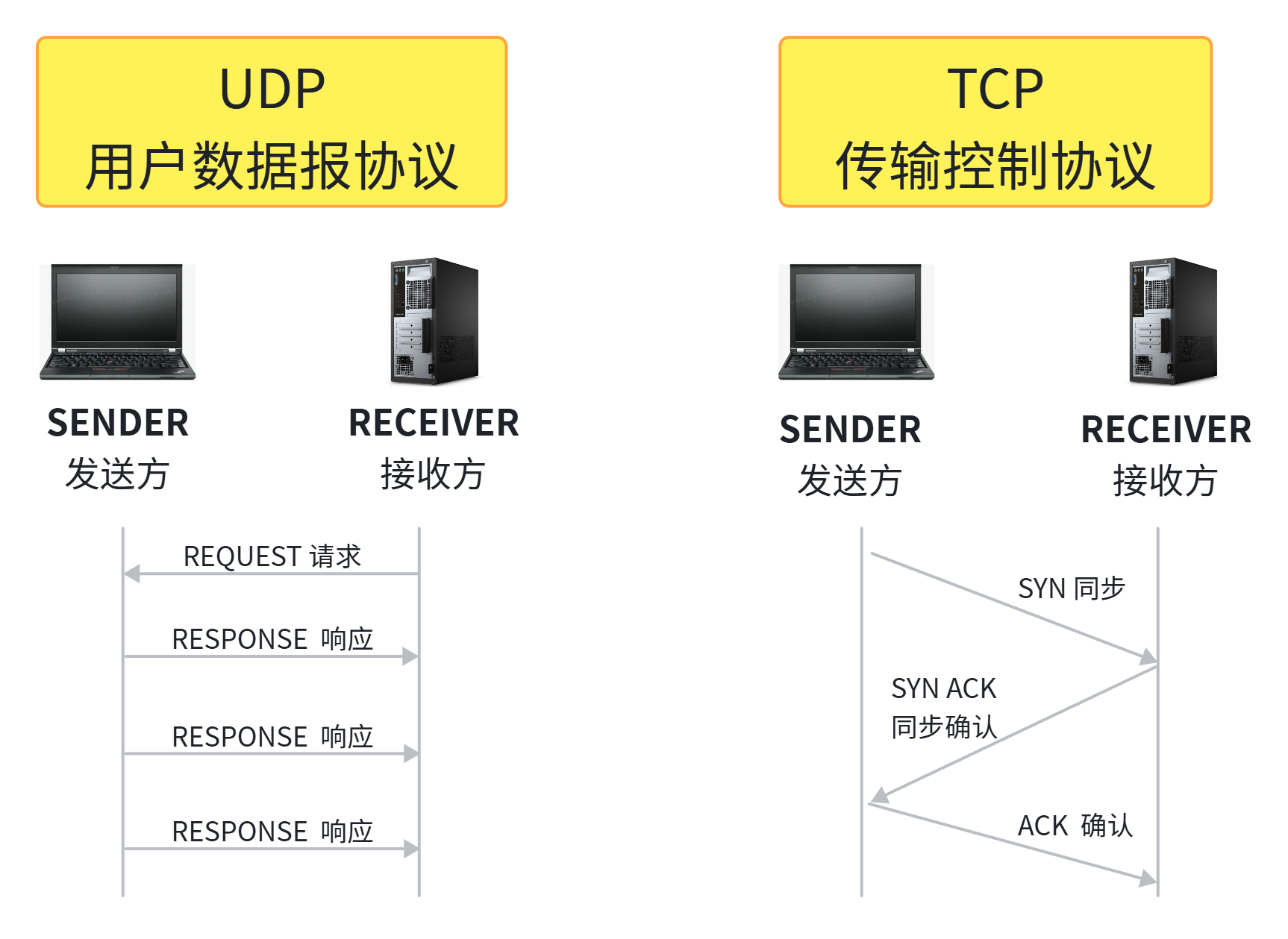
In summary: TCP is connection‑oriented. Handshake confirmation and re‑transmission logic guarantee correct data reception. It sacrifices partial transmission speed in exchange for transmission reliability and packet ordering, suiting scenarios requiring stable error‑free delivery such as web browsing and file transfer. UDP is connectionless. It skips complex reliability‑mechanisms including acknowledgments and retransmissions without pre‑setup or state‑maintenance. UDP does not guarantee successful delivery or in‑order arrival. It prioritizes speed trading away reliability and ordering for latency‑critical use‑cases such as video conferencing and online games.
5.3 Basic data unit: segment
Transport‑Layer data units are called segments. TCP‑generated units are TCP segments; UDP‑generated units are UDP datagrams.
Example TCP‑segment structure:
+------------------------------------------------------------+
| Source Port: 12345 (16 bits)             | Dest Port: 80 (16 bits)|
+------------------------------------------------------------+
| Sequence Number: 1000 (32 bits)                                       |
+------------------------------------------------------------+
| Acknowledgment Number: 2000 (32 bits)                                     |
+-------------------+-------+-----------+--------------------+
| Data Offset: 5 (4 bits)| Reserved (6 bits) | Flags: 0x18 (PSH, ACK) |
+-------------------+-------+-----------+--------------------+
| Window Size: 4096 (16 bits)                                    |
+------------------------------------------------------------+
| Checksum (16 bits)                    | Urgent Pointer: 0 (16 bits) |
+------------------------------------------------------------+
| Options: (optional, 0 bits)                                       |
+------------------------------------------------------------+
| Data: "Hello, TCP!" (10 bytes)                             |
+------------------------------------------------------------+
Sample assumptions: source‑port 12345, destination‑port 80 HTTP, sequence‑number 1000, acknowledgment‑number 2000, window‑size 4096, payload text “Hello, TCP!”. Flag‑field value 0x18 sets PSH and ACK bits. Checksums validate payload integrity.
TCP‑segment field descriptions:
Source Port Port number belonging to transmitting application endpoint.
Destination Port Port number belonging to receiving application endpoint.
Sequence Number Segment sequence identifier preserving packet ordering.
Acknowledgment Number Acknowledges last‑successfully‑received sequence value.
Data Offset TCP‑header length measured in 32‑bit words (4‑byte units).
Reserved Reserved bit‑field normally set to zero.
Flags Control bits including URG, ACK, PSH, RST, SYN, FIN.
Window Size Flow‑control value advertising receiver‑available‑buffer capacity.
Checksum Error‑detection checksum covering TCP header and payload content.
Urgent Pointer Points toward urgent‑data offset when URG flag is activated.
Options Optional variable‑length header field for extended control parameters.
Data Actual application‑payload content.
Example UDP‑datagram structure:
+------------------------------------------------------------+
| Source Port: 12345 (16 bits)             | Dest Port: 53 (16 bits)|
+------------------------------------------------------------+
| Length: 18 (16 bits)                  | Checksum: 0x1234 (16 bits) |
+------------------------------------------------------------+
| Data: "Hello, UDP!" (10 bytes)                             |
+------------------------------------------------------------+
Sample assumptions: source‑port 12345, destination‑port 53 DNS, total‑datagram‑length 18 bytes including 8‑byte UDP header, payload “Hello, UDP!”.
UDP‑datagram field descriptions:
Source Port Transmitter‑side application‑port identifier.
Destination Port Receiver‑side application‑port identifier.
Length Full byte‑count for entire UDP datagram including header plus payload sections.
Checksum Checksum field for error‑detection purposes.
Data Actual upper‑layer application payload content.
6.OSI Session Layer
6.1 Core Session concepts
Within computer‑network communications, a Session represents the complete exchange workflow between two or more devices, users or applications. Sessions span connection establishment, ongoing data exchange and final connection teardown. Sessions can be short‑lived such as one‑shot HTTP requests or long‑running such as persistent post‑login interactive connections.
Session workflow phases:
Session establishment Communication peers negotiate and initialize connections. This phase typically includes authentication, resource allocation and session‑parameter agreement.
Session management During active sessions Session Layer supervises data transmission, synchronization and error‑control ensuring in‑order data arrival plus recovery capabilities after connection interruptions.
Session termination Session Layer releases allocated resources and closes connections upon workflow completion. Proper termination prevents resource leaks and unnecessary resource occupation.
Simply described, sessions represent logical connections built between two specific application endpoints.
Session categories based on duration:
Persistent session Maintains open connections for full communication lifecycles. Suited for interactive workloads such as online chat, video conferences and remote‑desktop sessions.
Non‑persistent session Short‑lived one‑shot interaction patterns. Each request‑response pair operates independently without sustaining open connections. Most classic HTTP requests belong to this category.
Supported communication modes depending on application‑software and hardware capabilities:
Simplex Mode Data travels in one single direction only. One device transmits; the other only receives. Example: keyboard‑to‑computer input flows.
Half‑Duplex Mode Bidirectional communication without simultaneous transmit‑receive operations. Peers alternate sending and receiving. Example: walkie‑talkie devices.
Full‑Duplex Mode Simultaneous two‑way data transmission. Both sides send and receive concurrently. Examples: telephone conversations and modern Ethernet connections.
6.2 Client‑Server model and Request‑Response model
Client‑Server architecture and Request‑Response patterns form foundational computer‑network concepts describing data‑transfer and processing workflows for network‑based applications.
Client‑Server model partitions computing tasks into client components and server components. Clients submit service requests; servers deliver requested services.
Client Application software or hardware device requesting information or services. Clients transmit requests toward servers across networks and await response data.
Server Application software or hardware device providing information and services. Servers accept incoming client‑side requests, process business logic and return corresponding response payloads.
Request‑Response pattern is one concrete communication implementation built upon Client‑Server architecture. Interactions consist of sequential request‑response message pairs.
Request Client‑originated message containing desired operations or target‑resource parameters.
Response Server‑generated return payload carrying processing outputs, requested resource data or error notifications.
Multiple consecutive request‑response exchanges compose one complete session. Web‑browser‑web‑server interaction during webpage‑browsing serves as practical example:
- Client sends request toward server containing request type, target‑resource path and argument parameters.
- Server receives and processes incoming requests executing database queries or computational logic.
- Server returns response payload including execution outputs, resource data and status codes.
- Client receives responses and performs local rendering or interface‑update actions.
6.3 Core Session‑Layer functions
Within OSI stack Session Layer Layer 5 establishes, manages and terminates application‑level sessions. Main capabilities:
Session control Manage session creation, maintenance and teardown workflows.
Synchronization Implement data‑stream checkpointing enabling session recovery resuming from checkpoints after unexpected disconnections.
Dialogue control Regulate conversation directions inside full‑duplex communication preventing data‑collision conditions.
Session‑layer protocols include fault‑resolution mechanisms preserving reliability and data‑integrity:
Error detection and correction Detect and fix transmission‑induced corruption utilizing checksums and CRC Cyclic‑Redundancy‑Check algorithms.
Retransmission mechanism Trigger re‑transmission for lost or corrupted detected frames‑packets.
Timeout and retry logic Resend requests when expected responses fail to arrive within defined time windows.
Session recovery Resume interrupted communication from last‑saved synchronization checkpoints minimizing data loss.
6.4 Common Session‑Layer protocols
Several protocols and technologies exist at OSI Session‑Layer Layer 5 managing communication‑session lifecycles.
NetBIOS Network‑Basic‑Input‑Output‑System NetBIOS is network‑communication API supplying Session‑Layer and Presentation‑Layer services enabling application‑level LAN communication.
Core capabilities Session establishment and termination functions. Session‑management and session‑control features. Name‑resolution and datagram services helping applications discover and access remote network hosts.
Application scenarios Primarily deployed for LAN‑based file‑and‑printer sharing. Widely utilized for Windows‑host‑to‑Windows‑host network communication inside Microsoft‑centric networks.
RPC Remote‑Procedure‑Call Protocol RPC enables programs to invoke remote‑host subroutines over networks similarly to invoking local‑host functions.
Core capabilities Execute remote service invocations across network boundaries. Manage session setup, data transfer and session‑teardown workflows. Support synchronous‑call and asynchronous‑call execution patterns.
Application scenarios Application‑to‑application communication inside distributed‑computing environments. Client‑side invocation of remote‑host services within distributed network‑systems.
PPTP Point‑to‑Point‑Tunneling Protocol PPTP is VPN Virtual‑Private‑Network tunneling protocol.
Core capabilities Create encrypted secure communication tunnels transmitting payload data across public internet infrastructure. Manage tunnel‑establishment, tunnel‑maintenance and tunnel‑teardown workflows.
Application scenarios Remote‑access VPN granting secure access toward corporate internal network resources.
SMB Server‑Message‑Block Protocol SMB protocol handles network‑based file‑sharing, printer‑sharing and serial‑port‑sharing workflows.
Core capabilities Deliver file‑sharing and printer‑sharing network services. Manage session‑establishment and session‑termination workflows. Implement file‑read‑write operations plus shared‑access permission management.
Application scenarios File‑and‑printer‑sharing operations within Windows‑based networks. File‑sharing workflows inside NAS Network‑Attached‑Storage hardware devices.
7.OSI Presentation Layer
7.1 Core Presentation‑Layer functions
OSI Presentation Layer is Layer 6. Presentation Layer handles data formatting, encryption‑decryption and compression‑decompression workflows. It represents final processing stage before application data departs local hosts over networks, and first processing stage for inbound network‑data arriving toward local applications. Primary responsibilities:
Data formatting Transform raw data into representation formats understandable by receiving‑side applications.
Data encryption Encrypt payload content protecting confidentiality during network transit.
Data compression Compress outgoing payloads shrinking transmission volume improving communication efficiency.
Data decompression Decompress inbound compressed payloads restoring original data representation formats.
Data‑access control Enforce data‑access permission rules guaranteeing content security.
7.2 Data‑formatting standards at Presentation Layer
ASCII American‑Standard‑Code‑for‑Information‑Interchange
Overview ASCII is seven‑bit character‑encoding standard originally designed for information‑exchange workflows. It defines 128 distinct characters including Latin‑alphabet letters, numeric digits, punctuation symbols and control‑characters such as newline markers.
Characteristics Seven‑binary‑bit values represent individual characters ranging numerically from 0 up to 127. High‑compatibility and simplicity lead to broad adoption across text‑file and data‑exchange workflows.
Extensions ISO‑8859‑1 also known as Latin‑1 is ASCII superset adding extra glyphs and symbols required for Western‑European‑language text representation.
EBCDIC Extended‑Binary‑Coded‑Decimal‑Interchange‑Code
Overview EBCDIC is IBM‑designed eight‑bit character‑encoding standard mainly targeting mainframe‑computer systems. It is incompatible with ASCII specifications.
Characteristics Eight‑binary‑bit values represent each character covering numerical range 0‑255. Primarily used within legacy IBM‑mainframe environments; incompatible against contemporary‑computer and internet standards.
Application scenarios Data‑processing and‑storage workflows running on legacy mainframe‑hardware platforms.
Unicode
Overview Unicode universal‑character‑encoding standard assigning unique code‑points for every writing‑system glyph across global human languages. It supports multiple concrete encoding implementations including UTF‑8, UTF‑16, UTF‑32.
Characteristics UTF‑8: variable‑byte‑length encoding using one‑to‑four bytes for each character, maintains backward‑compatibility with ASCII; most widely‑deployed Unicode variant. UTF‑16: uses two‑byte or four‑byte units representing all Unicode‑defined glyphs. UTF‑32: fixed four‑byte‑per‑character representation supporting complete Unicode repertoire at cost of higher memory overhead.
Application scenarios Unicode enables unified processing and rendering for multilingual‑character‑sets. It sees heavy adoption across modern‑computer software and internet‑based services supporting worldwide‑language text content.
7.3 Network‑security protocols
SSL Secure‑Sockets‑Layer and TLS Transport‑Layer‑Security are network‑security‑protocol suites encrypting network‑based communications guaranteeing payload confidentiality and integrity during transit. TLS succeeds older SSL standards delivering strengthened security and functional improvements.
SSL Secure‑Sockets‑Layer: SSL was originally developed by Netscape to protect communication confidentiality and content integrity across network links. SSL achieves secure transport through payload encryption, tamper‑protection and communicating‑party identity‑verification workflows.
SSL major versions: SSL 2.0 1995 earliest public SSL release containing known security vulnerabilities. SSL 3.0 1996 improved upon SSL 2.0 yet retains documented security weaknesses.
TLS succeeds SSL and is standardized under IETF Internet‑Engineering‑Task‑Force governance. TLS strengthens cryptographic primitives and authentication mechanisms ensuring communication confidentiality, integrity and peer‑identity validation.
TLS major versions: TLS 1.0 1999 derived from SSL 3.0 with incremental refinements. TLS 1.1 2006 further security hardening fixing known TLS 1.0 vulnerabilities. TLS 1.2 2008 adds support for stronger cryptographic algorithms enhancing protocol‑security posture. TLS 1.3 2018 simplifies handshake workflows delivering stronger encryption, improved performance plus enhanced privacy protections.
SSL‑TLS operational workflow phases:
Handshake Phase Client‑server parties establish secure logical connections negotiating cryptographic‑algorithm suites and key‑material information. Server side presents digital‑certificate credentials; client validates certificate authenticity. Both sides negotiate cipher suites and generate session‑keys used for subsequent payload‑encryption.
Data‑Transfer Phase Client‑server endpoints encrypt‑decrypt application payload data utilizing negotiated cipher suites and derived session‑keys. Application data transmits securely resisting eavesdropping and tampering‑attacks.
Termination Phase Client‑server parties tear down secure sessions and release allocated session‑related resources.
8.OSI Application Layer
8.1 Core Application‑Layer functions
OSI Application Layer is Layer 7 representing uppermost stack layer delivering network‑services directly toward end‑user application software. It mediates interactions between application‑program logic and underlying network infrastructure providing end‑user‑facing functional capabilities. Applications mean operating‑system‑installed software packages such as Firefox web‑browser or Microsoft‑Word word‑processor. Certain background‑running software components execute dedicated network‑functions. For example email‑client applications utilize SMTP, POP3 or IMAP protocols to transmit‑receive email content. All those protocols execute within Application Layer ensuring correct email delivery.
Major Application‑Layer responsibilities:
Network‑service provision Implement end‑user‑visible network‑services including email, file‑transfer and web‑browsing capabilities.
Protocol support Host diverse Application‑Layer protocols defining application‑to‑application network‑communication rules.
Data formatting Convert application‑generated data payloads into network‑transmittable representation formats.
User‑interface capabilities Supply user‑interaction points enabling human‑triggered network‑operation execution.
Session‑management interaction Cooperate with Session‑Layer subsystems for session‑setup‑maintenance‑teardown workflows even though core session logic lives inside Session Layer.
8.2 Common Application‑Layer protocols
Application Layer hosts many different protocols supporting varied network‑services and workloads.
FTP File‑Transfer‑Protocol Realizes network‑based file‑transfer workflows supporting file‑upload‑download operations plus file‑management actions such as deletion and renaming.
SSH Secure‑Shell Delivers encrypted remote‑system‑access and remote‑administration capabilities enabling secure remote login, command‑execution and system‑management across network boundaries.
SMTP Simple‑Mail‑Transfer‑Protocol Used for outgoing‑email transmission. Defines rules governing email‑server message‑sending and message‑relay workflows.
IMAP Internet‑Message‑Access‑Protocol Grants access and management control toward email‑messages stored on remote mail‑servers. Supports server‑side mail‑storage offering flexible email‑access‑management capabilities.
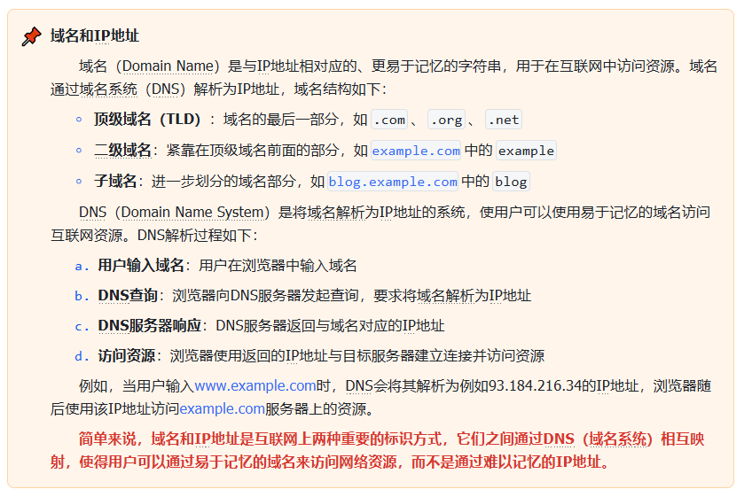
DNS Domain‑Name‑System Translates human‑readable domain‑names into machine‑interpretable IP‑address values enabling resource‑access via domain‑name strings. Supports name‑resolution, load‑balancing and service‑discovery functions.
HTTP Hypertext‑Transfer‑Protocol Powers web‑browsing and general‑purpose data‑transfer workflows. Defines request‑response interaction patterns between browser‑clients and web‑servers.